
Panel Wiring
01/01/14 21:40 Filed in: All
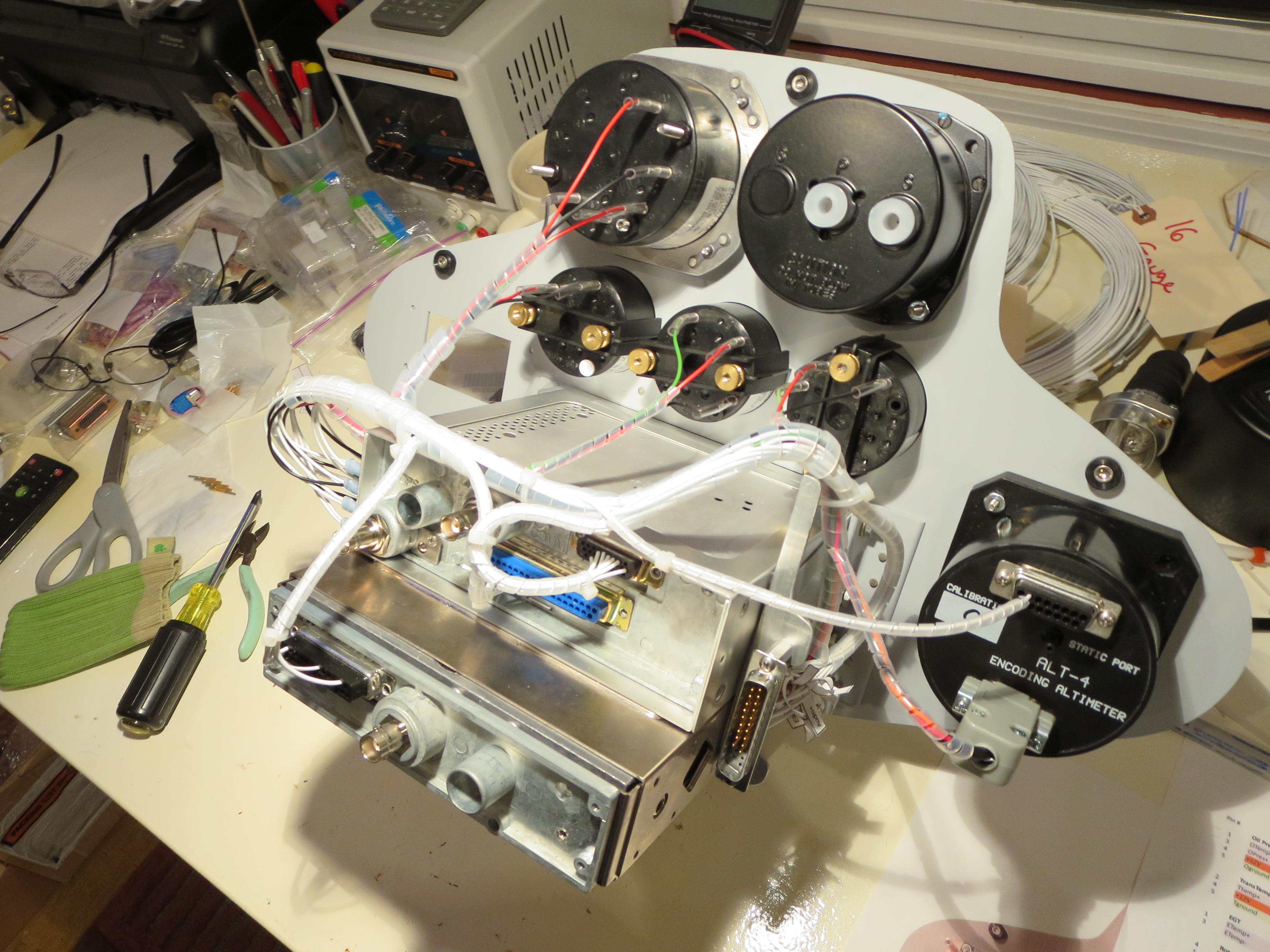
Instrument Cluster wiring harness is fabricated and installed. This is not especially hard, just tedious. I did not do a formal schematic since there is no real circuit design here, just connecting point A to point B. It was all tracked with spreadsheets. Once routed and the ends crimped, the bundles were lashed with spiral wrap nylon to tidy everything up. I drilled holes on the back of the GPS/COMM tray so everything could be hard-secured down. No wiggling wires. It is all very solid.
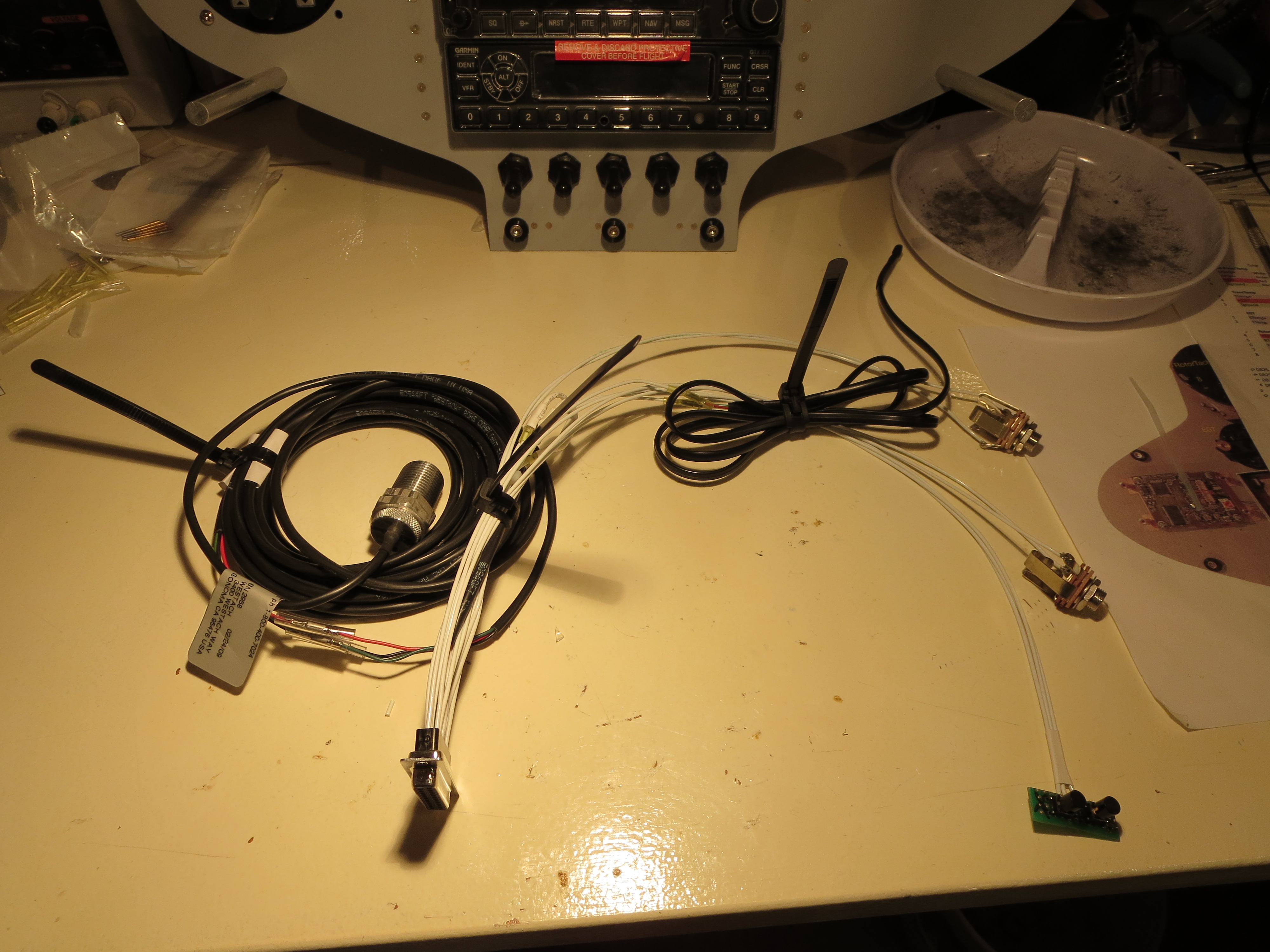
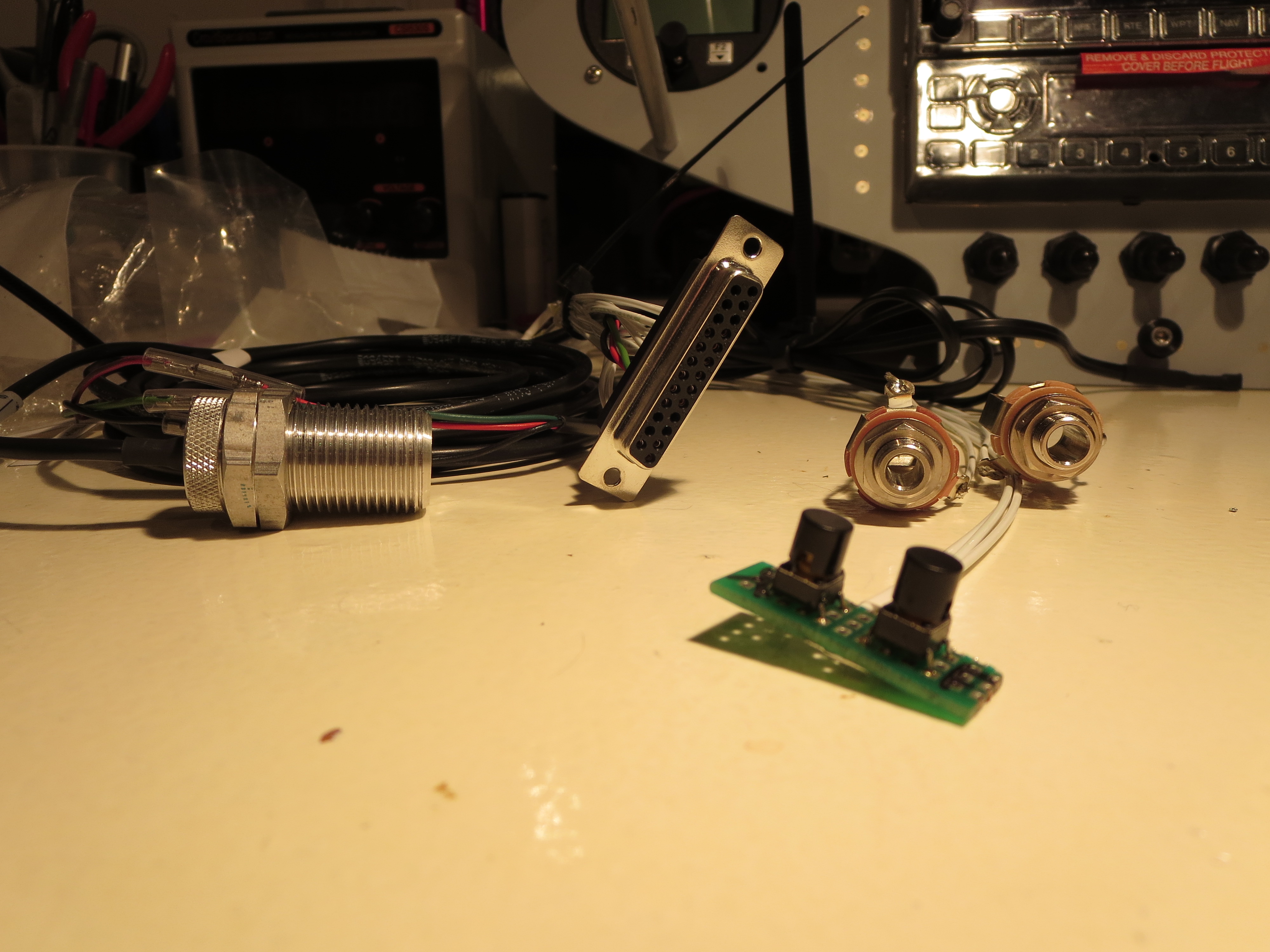
Of course once the wiring was done I had to make up a little test harness with power and switches for the XMIT and COMM flipflop as well as power and the sensors that NEED to be attached when powered up (the tach sensor).
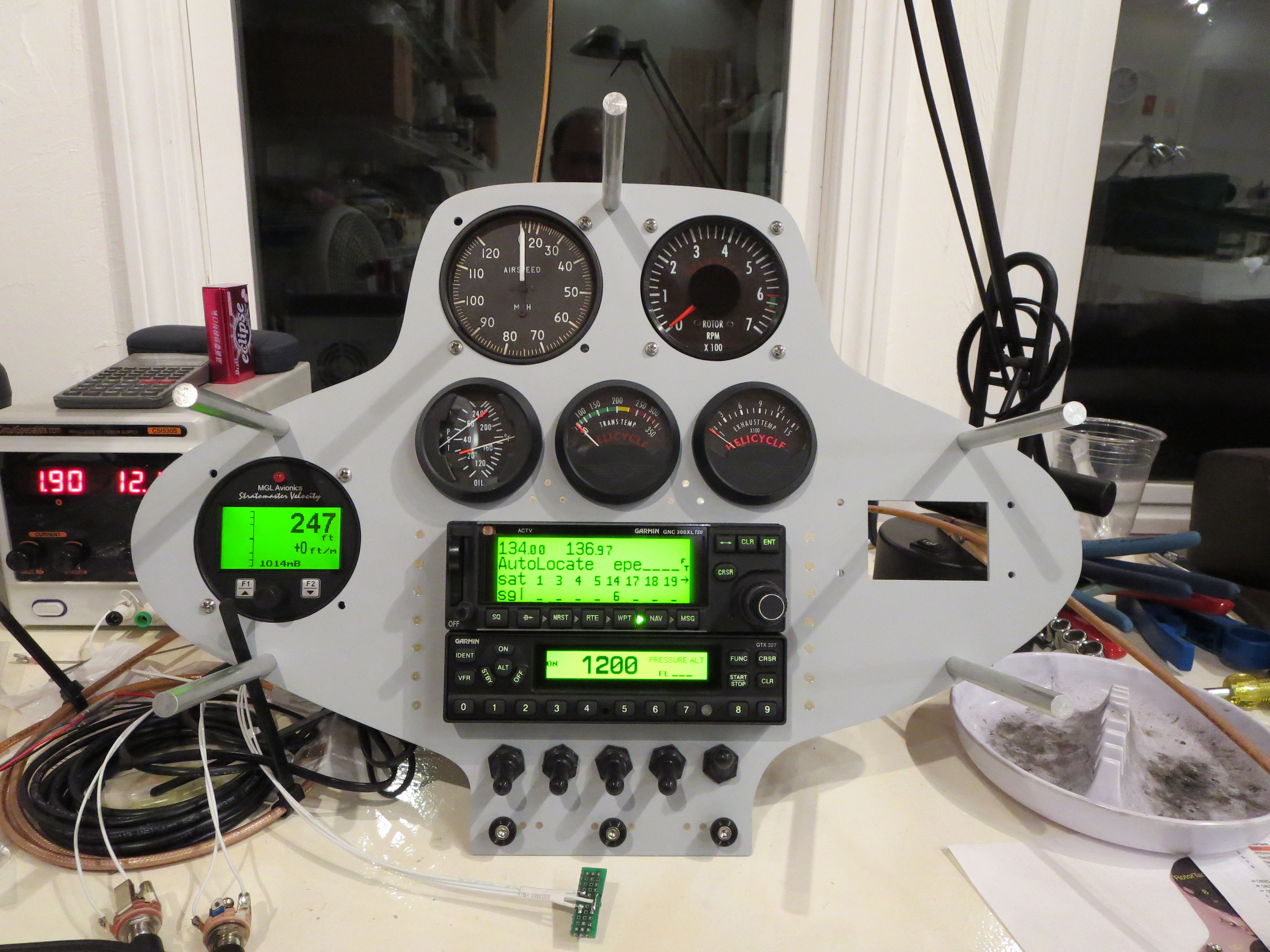
Ahhh the money shot! Everything powered up and is functioning OK as far as I can tell. I rigged up antennas and could send and receive over the radio to my handheld and get GPS position data accurately.
One thing that became immediately apparent is that the COMM draws HUGE current (comparatively) when transmitting versus receiving. Nominally the panel was drawing just under 2 amps, but it spiked to about 4 amps, and quickly dropped to 3 amps when transmitting. Wow.