
InstrumentPod
Switch Labels
10/21/15 23:08 Filed in: All
Finishing up the Instrument pod is coming right up. I have been toying with ways to label the switches and decided to try employing my CNC router. This current trial involved taking sheets of polystyrene, which can be found on Amazon for about $0.40/sheet.
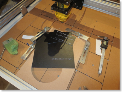
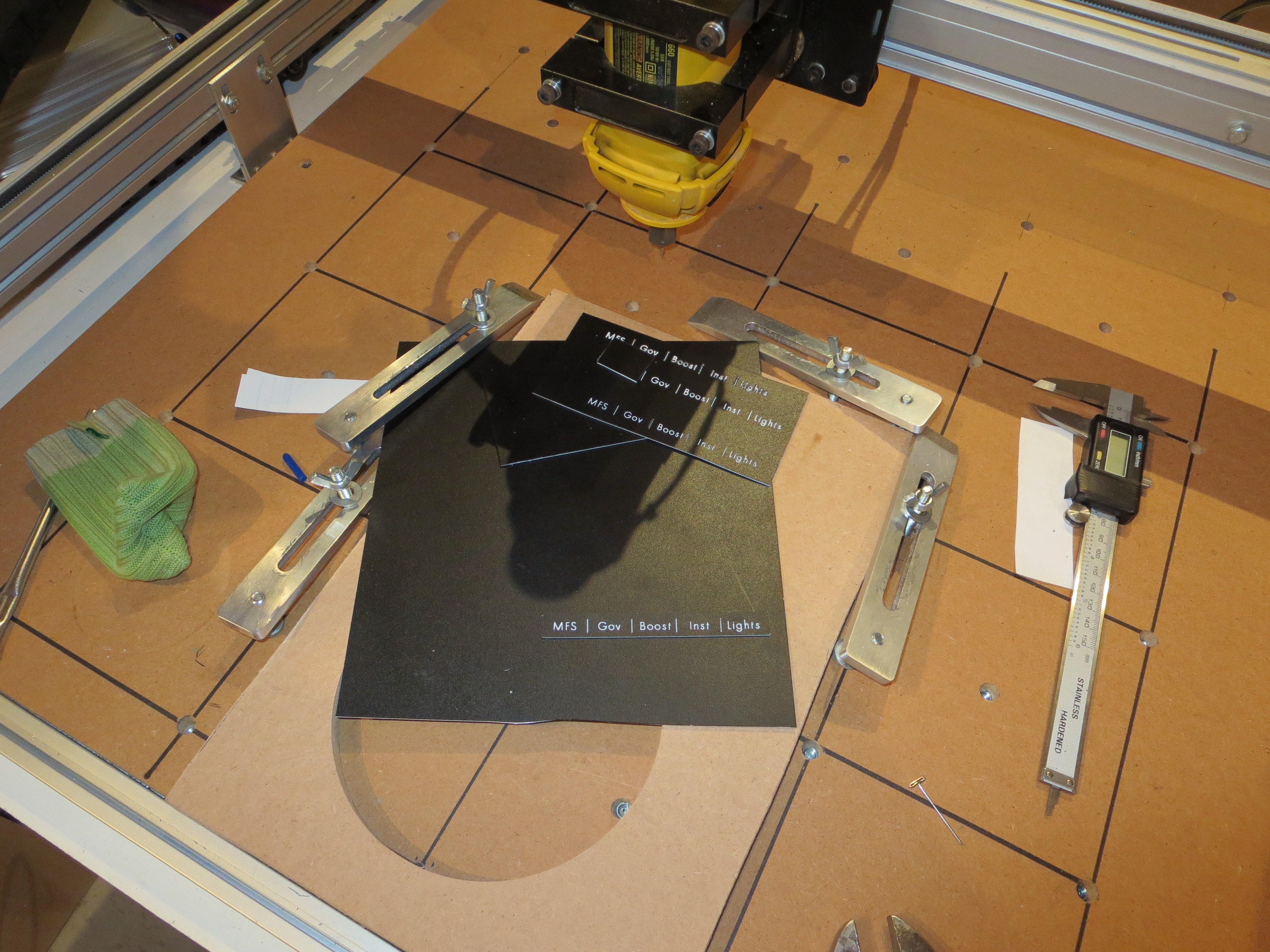
Paint the white sheets with a couple of heavy-ish coats of satin black, then route the labels with a very fine point engraving bit. It took a couple of tries to get the right bit and the correct depth, but I am quite satisfied with the results.
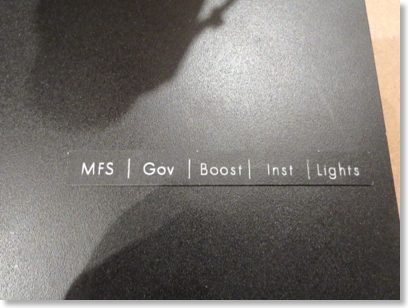
Since I have the detailed CAD for the panels I can easily come up with shapes that surround the entire switch area and are held in place by the switches. These are just test pieces, but I think I will go with this approach.
Rotor Tach
01/26/15 20:39 Filed in: All
A lot of builders have added expanded scale tachometers for the rotor. The gauge supplied by Eagle has a very narrow active range. In flight, reading the range while flying would be tough. The acceptable range is 610 to 620 which is just a couple of needle widths.
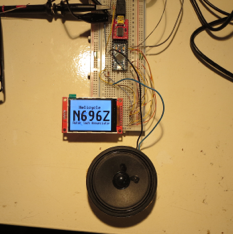
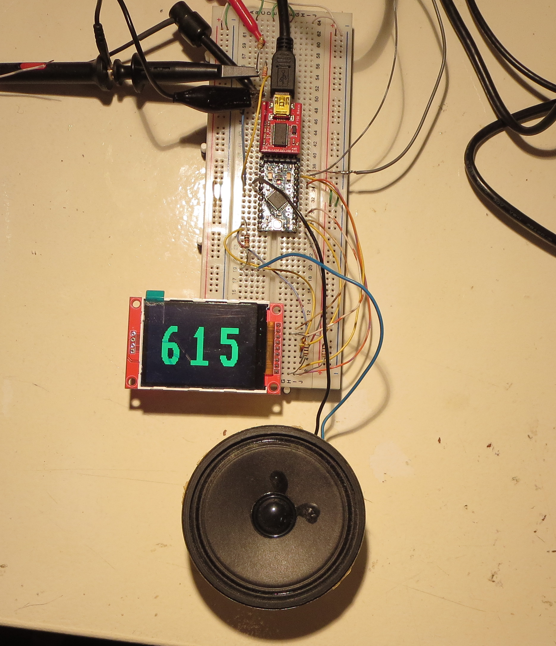
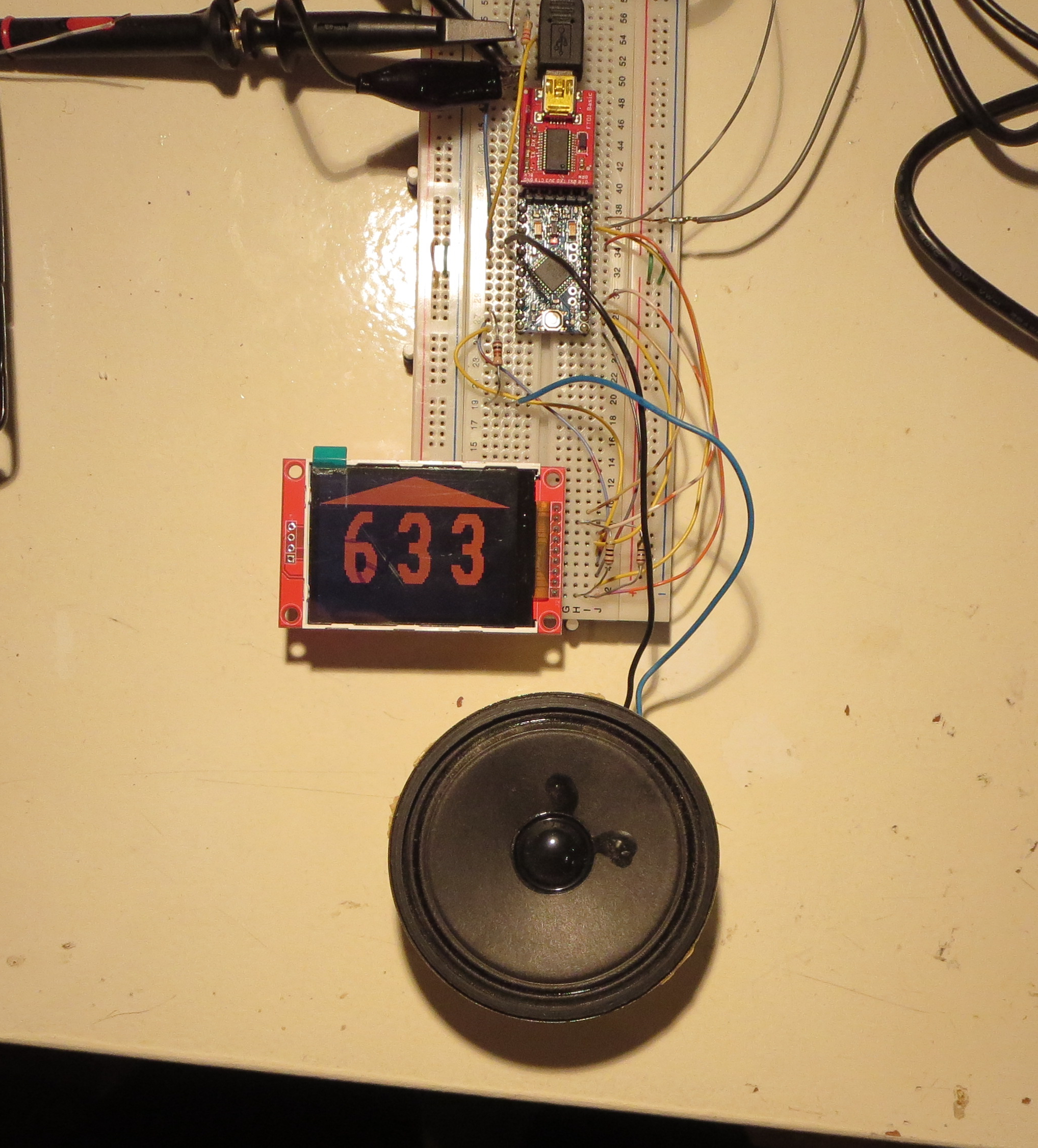
I built this little display item. It is based on a 2" display from eBay and an Arduino processor. There will need to be some conditioning to amplify the incoming signal and to make sure the analog tach is not affected. On the bench I use an audio tone generator to mimic the signal form the sensor.
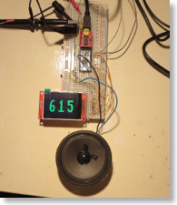
If the rotor is in the range of 610 to 620 the RPM is displayed in green.
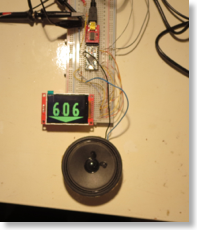
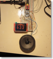
When in the range of 605 to 610 the RPM is yellow with a downward pointing arrow and a tone. Between 620 and 625 the RPM is also yellow with a higher pitched tone. Above 625 the reading is red with a red up arrow and a higher pulsing tone. Similarly below 605 it is also red with a red down arrow and a pulsing low pitch tone.
This is designed to be easy and very quick to read with an attention getting audio tone mixing in to the headset feed. I plan on mounting it on the top of the pod as it is critical to interpret this quickly during autorotations. In the final incarnation this will be packaged well and be brighter. The display shown here is a tired old one I have beaten and abused and use for development where I may actually damage it.

I built this little display item. It is based on a 2" display from eBay and an Arduino processor. There will need to be some conditioning to amplify the incoming signal and to make sure the analog tach is not affected. On the bench I use an audio tone generator to mimic the signal form the sensor.
If the rotor is in the range of 610 to 620 the RPM is displayed in green.

When in the range of 605 to 610 the RPM is yellow with a downward pointing arrow and a tone. Between 620 and 625 the RPM is also yellow with a higher pitched tone. Above 625 the reading is red with a red up arrow and a higher pulsing tone. Similarly below 605 it is also red with a red down arrow and a pulsing low pitch tone.
This is designed to be easy and very quick to read with an attention getting audio tone mixing in to the headset feed. I plan on mounting it on the top of the pod as it is critical to interpret this quickly during autorotations. In the final incarnation this will be packaged well and be brighter. The display shown here is a tired old one I have beaten and abused and use for development where I may actually damage it.
Lower Panel Crafted
01/28/14 21:50 Filed in: All
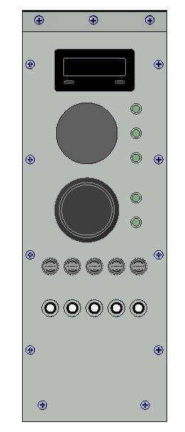
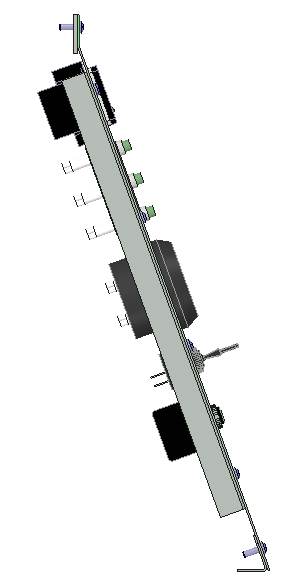
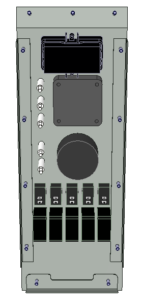
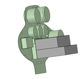
Start with a quick CAD model of the instruments and panel. If anyone is interested in the solid models I used, just email me and I will post them.
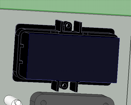
I almost neglected to model the rear retaining ring around the Red Lion tach. Can;t skip that because it's quite a large thing. Once everything is modeled, it is easy tp check for interferences and tweak the position if required.
Once the modeling is complete, add some dimensions and make a detailed drawing as I did HERE. This is the primary reference sheet when machining the holes in the sheet.
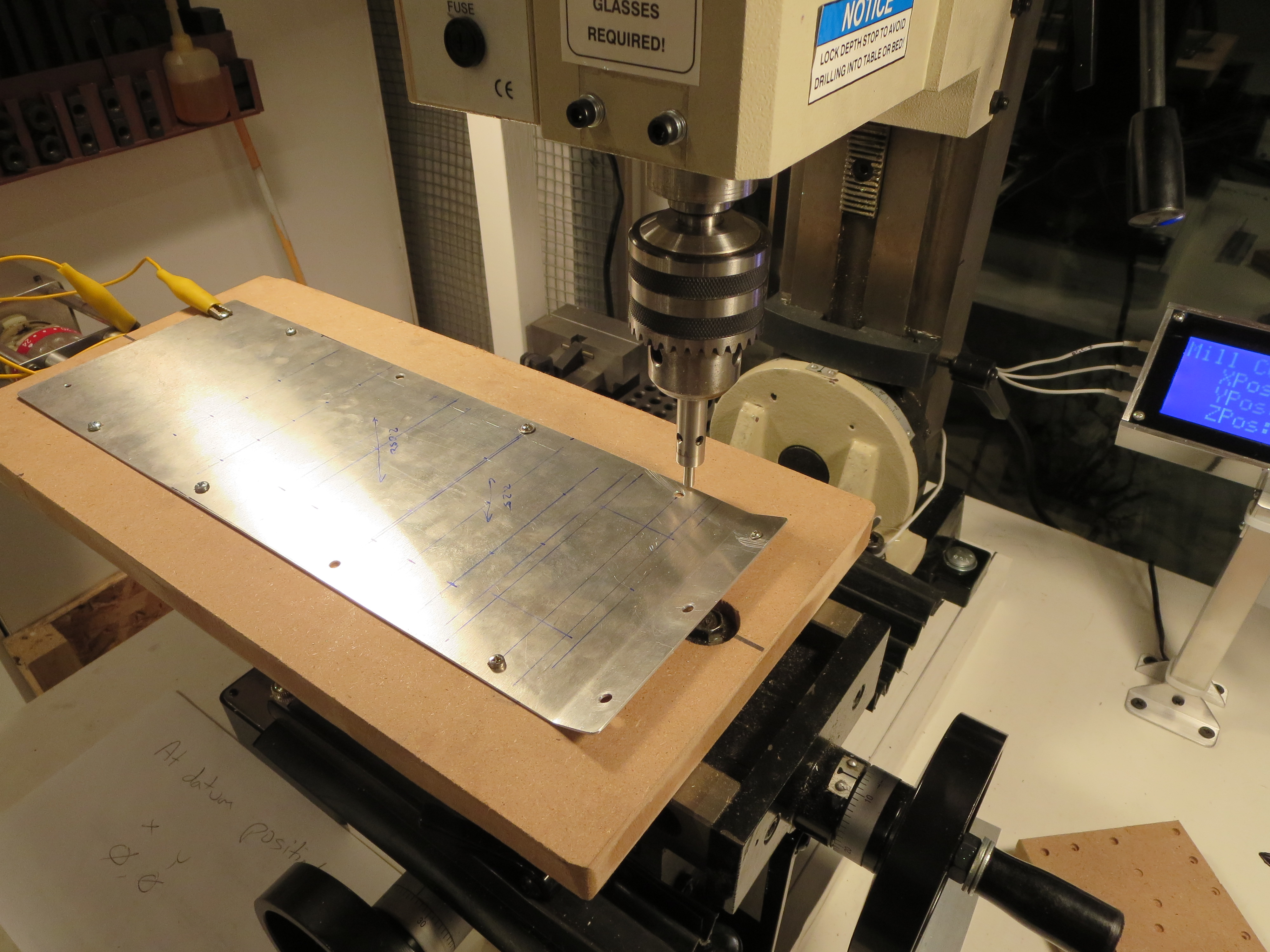
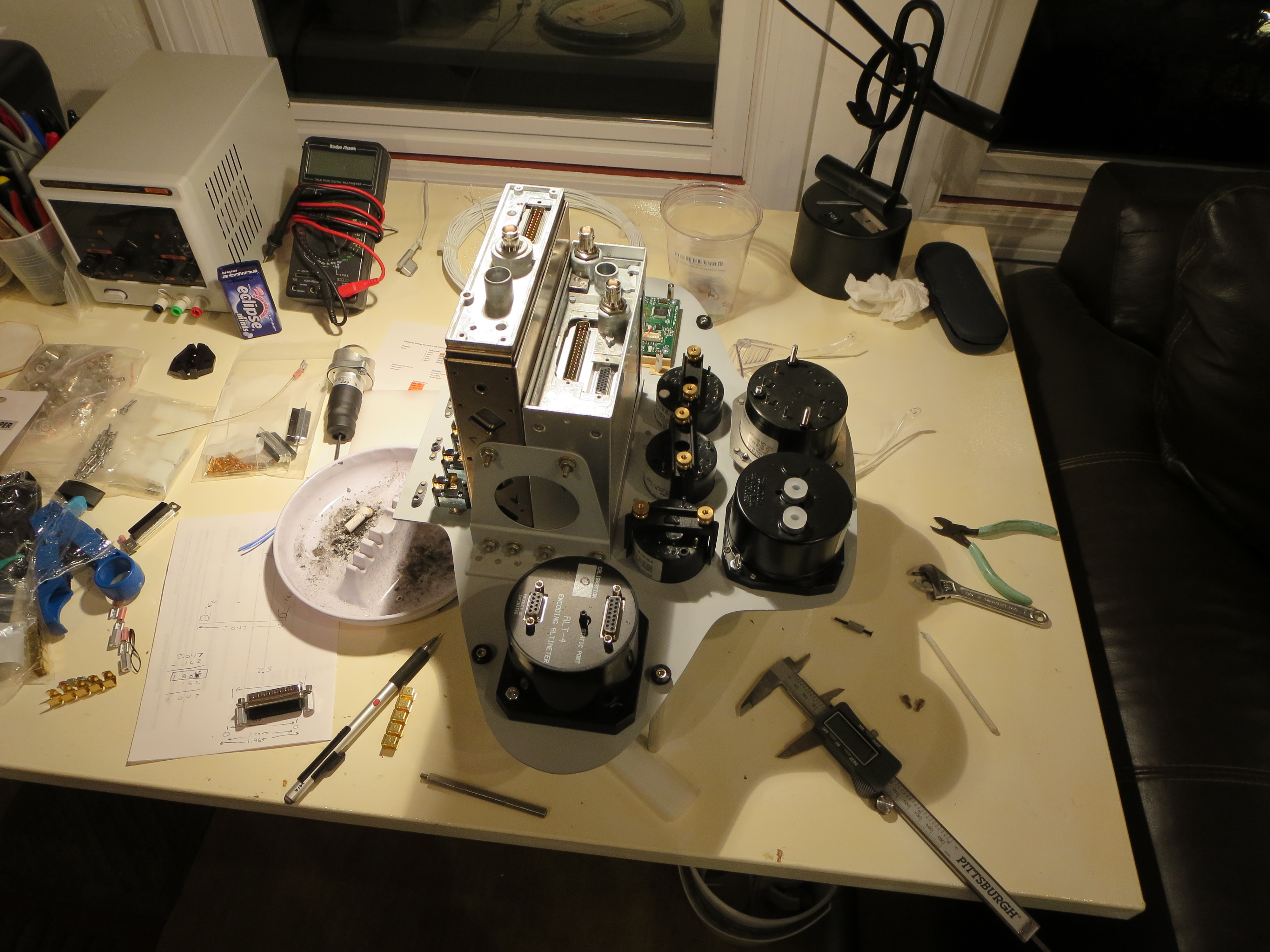
The blank queued up on the mill. Prior to this the blank had been cut and then fit into the instrument pod lower. The side mounting screws were drilled in assembly with the support strips in the pod. Perfect alignment prior to this drilling/milling operation.
On the mill I bolted a piece of MDF to the table (mounting bolt recessed, of course). Then the blank was trammed to the mill so the edge was in perfect parallel alignment with the quill. Very small wood screws are then screwed through the mounting holes to solidly affix is to the plate. The front mount hole and edge are the home reference.
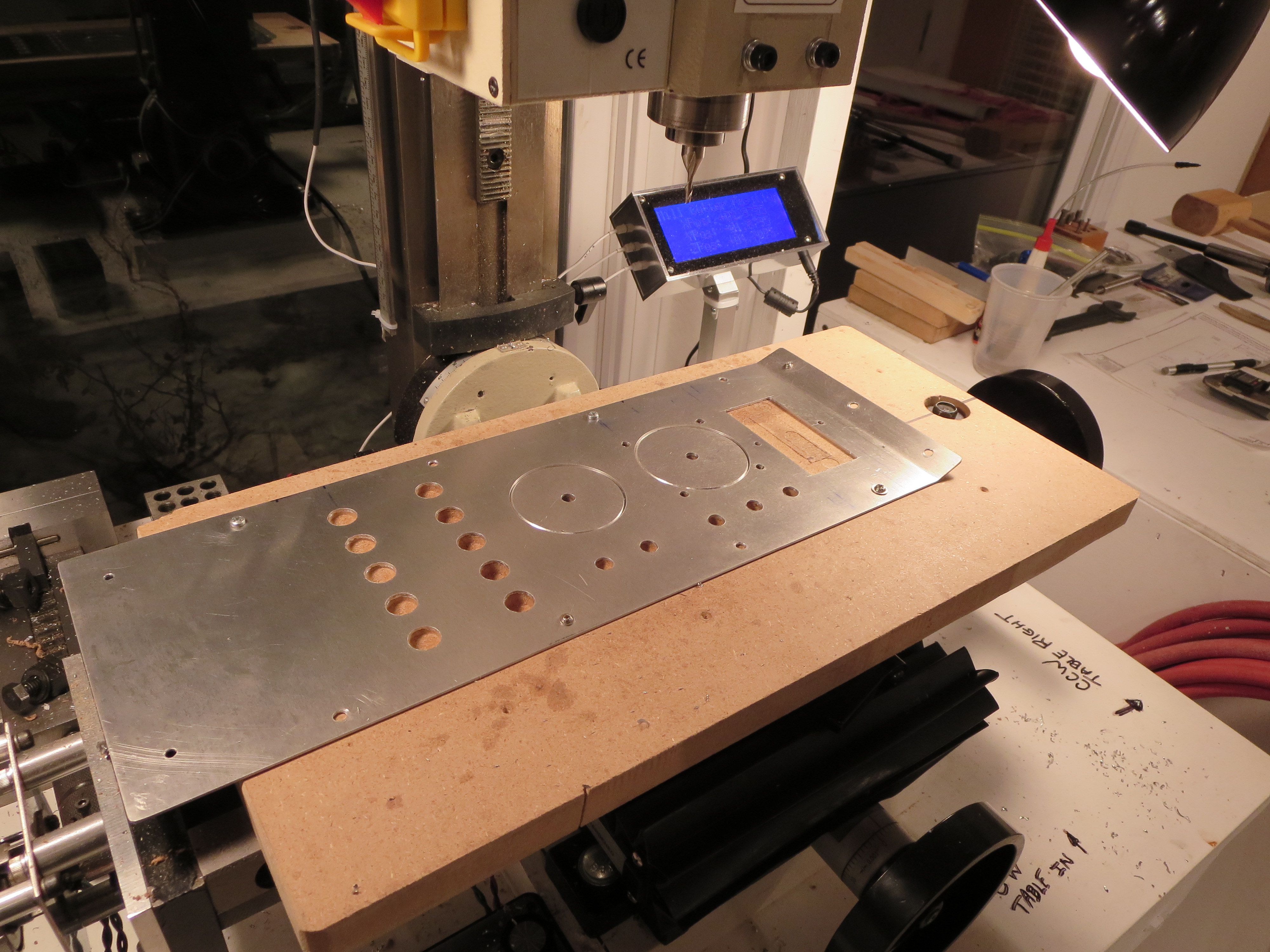
The Lower Panel machined. I love that little mill. Though time consuming, the accuracy is impressive. Digital readouts on each axis make repeatability and accurate positioning very easy. I used my hole jig for the circles, and milled out the tach square with a 3/8" end mill. The corners were finished with an 1.8" end mill. If needed I will file them down.
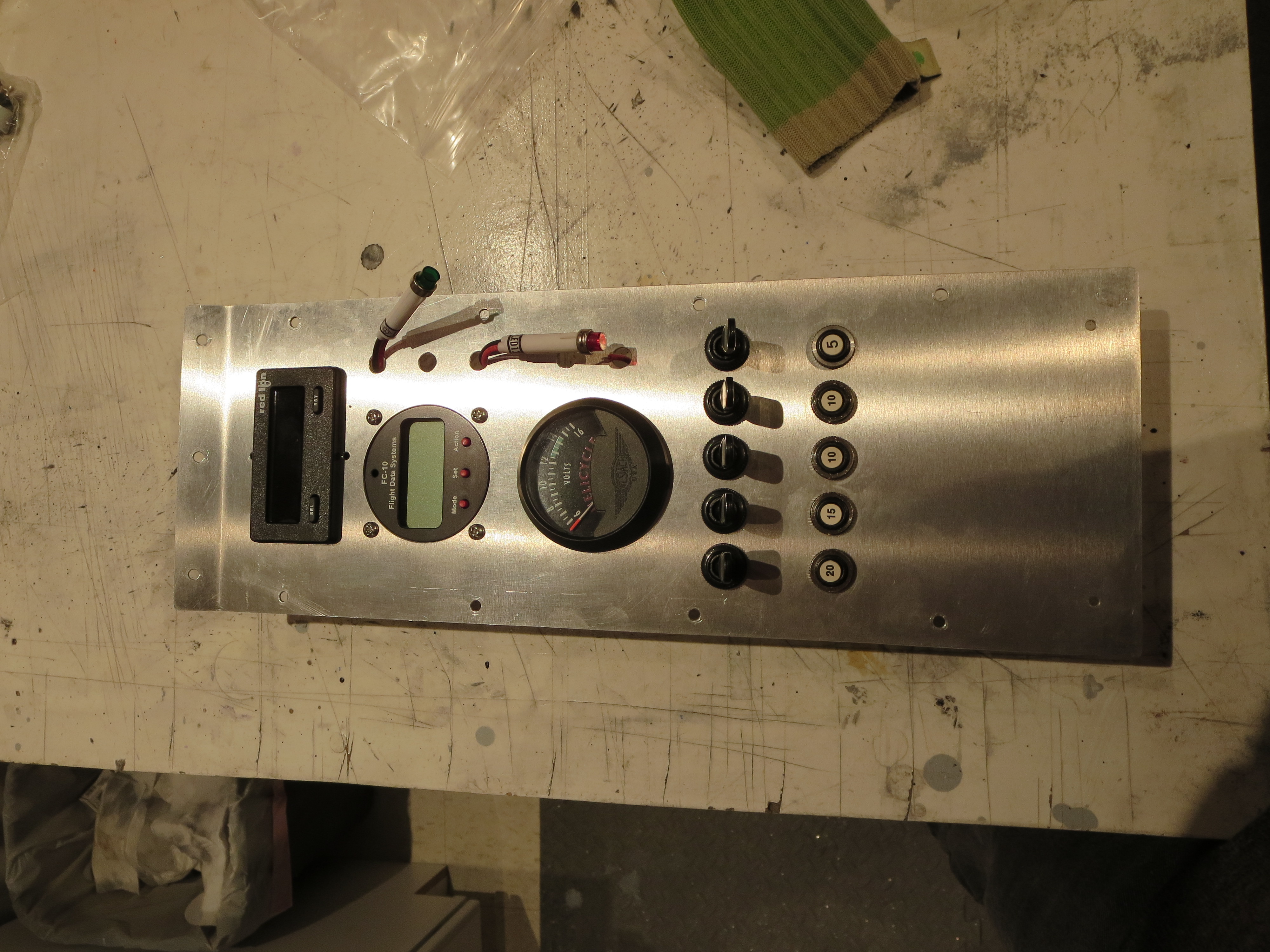
All the stuff preliminarily fitted. My holes for the indicator lights were a bit small and the fuel monitor hole needs some trimming, but by and large the fit is pretty good. All the holes are alignment nicely and very square.
Finished Packaging Compass
01/18/14 11:30 Filed in: All
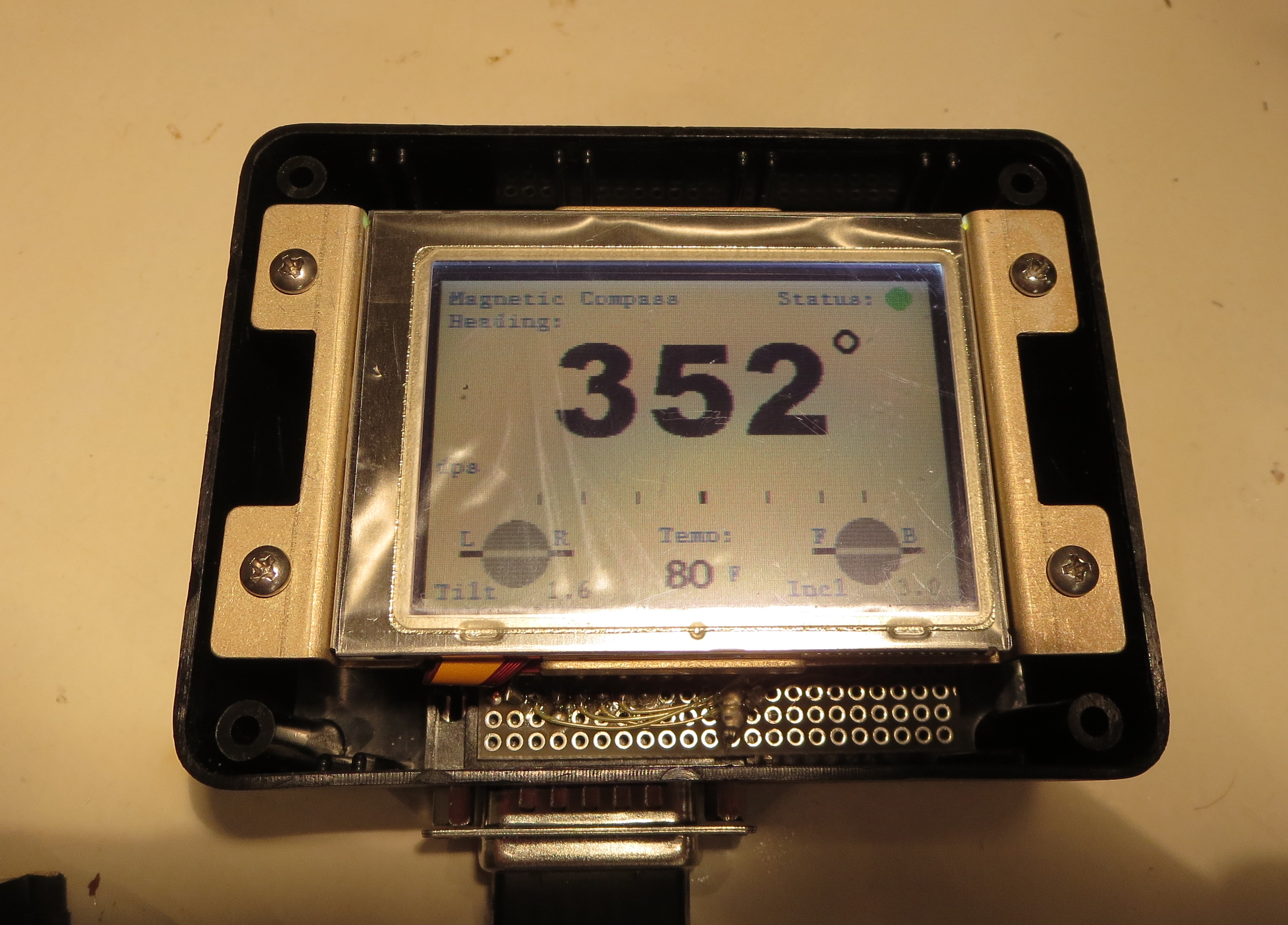
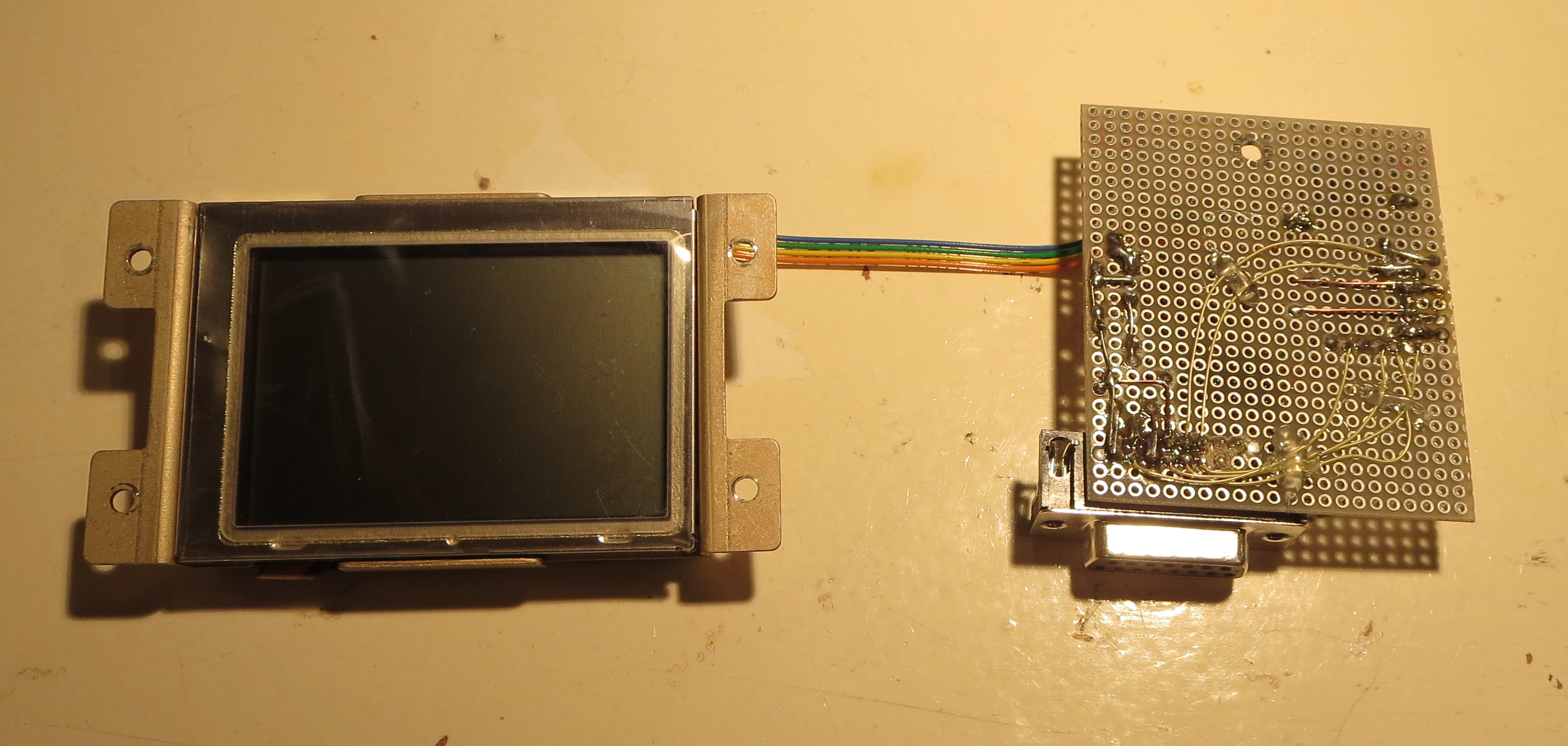
I finally finished packaging my homemade electronic compass. Small project box with some machined risers to house the thing.
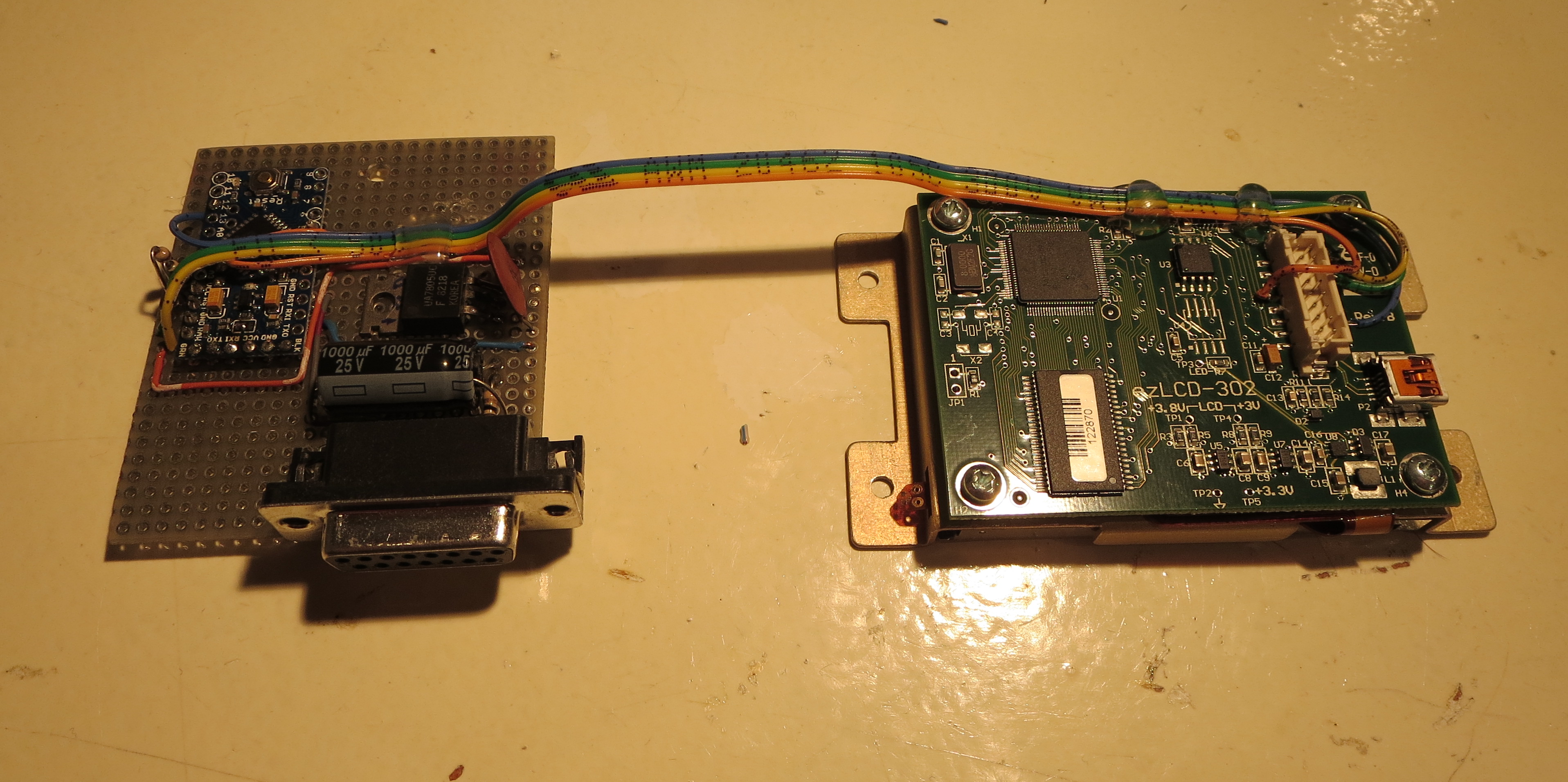
That's just an experimenter board with the Arduino mounted and a 7805 linear power supply. Power draw is 0.18A at 12V, so about 2.2W. More than I expected, but not too bad overall.
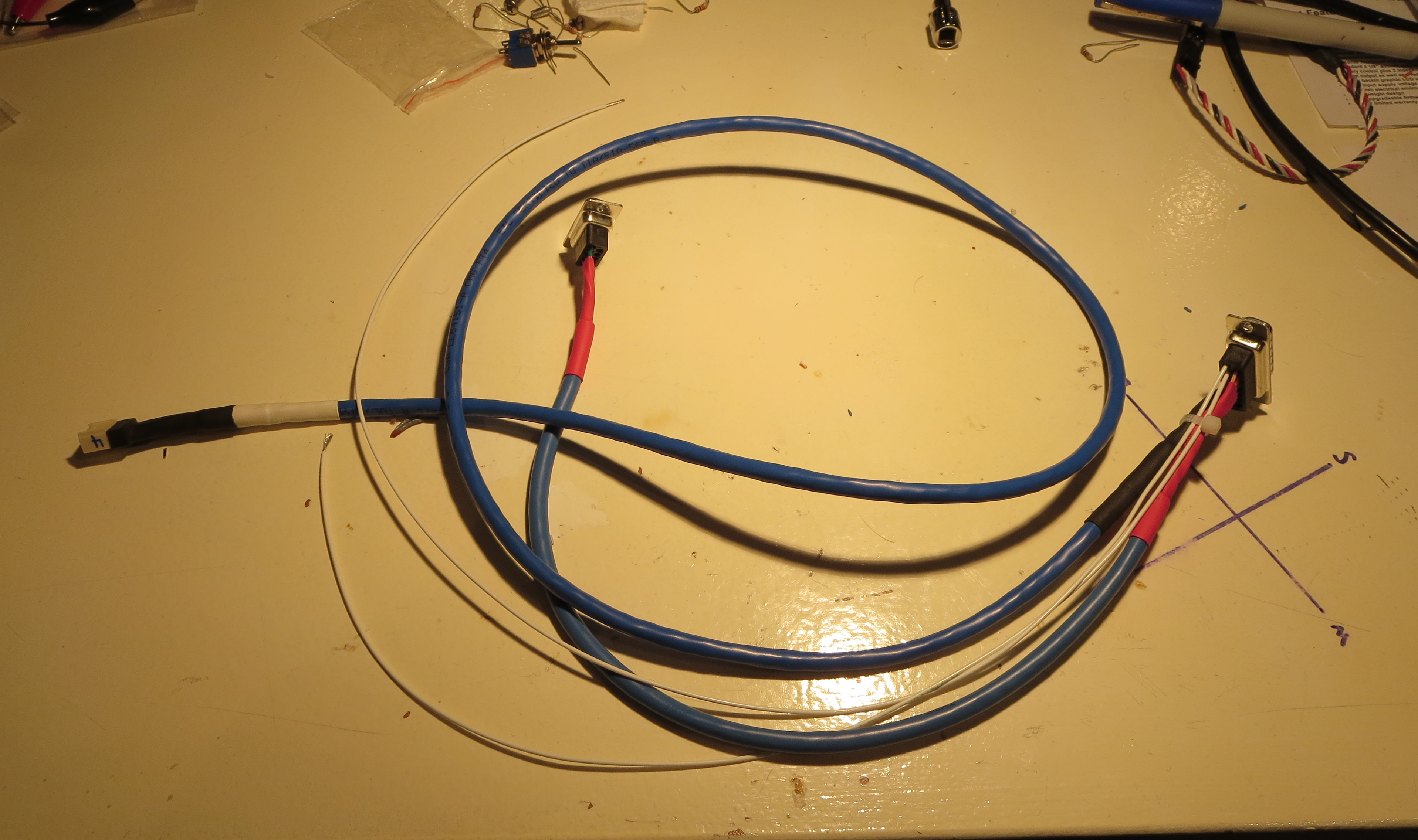
Custom wiring harness connects to unit, power, sensor, and a DSUB9 in case I want to update the firmware with calibration data once its in the bird.
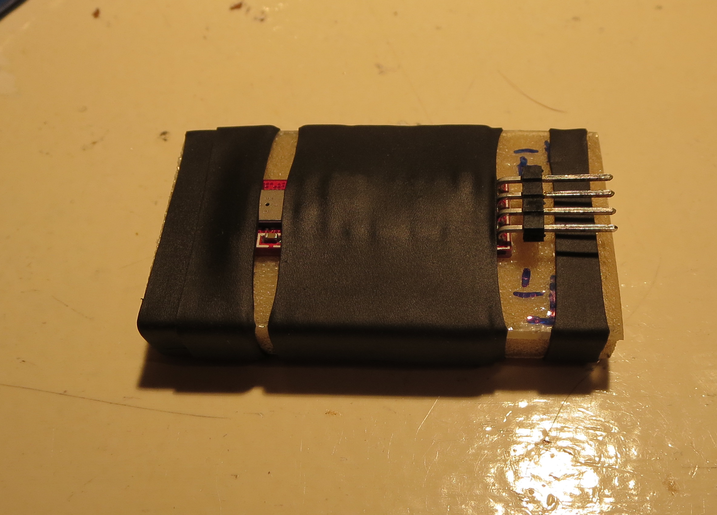
Sensor is shrink tubed to a little chunk of fiberglass. I will probably just tie wrap this to a fiberglass platform at the from of the pod's interior.
Wiring notes are here. I uses NotesPlus HD on the iPad to take hand notes in the shop. Better than paper and you get an instant electronic copy.
Panel Wiring
01/01/14 21:40 Filed in: All
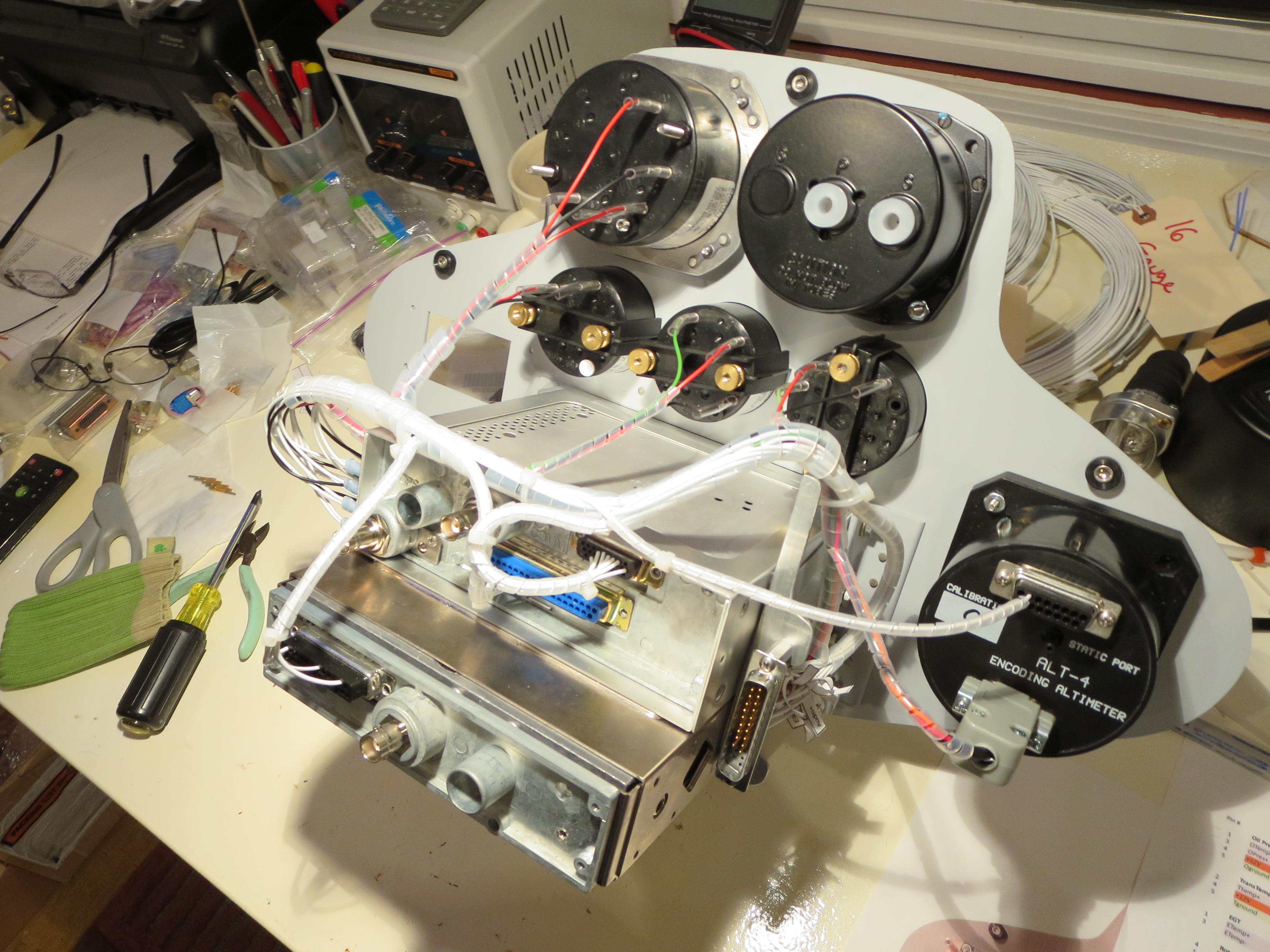
Instrument Cluster wiring harness is fabricated and installed. This is not especially hard, just tedious. I did not do a formal schematic since there is no real circuit design here, just connecting point A to point B. It was all tracked with spreadsheets. Once routed and the ends crimped, the bundles were lashed with spiral wrap nylon to tidy everything up. I drilled holes on the back of the GPS/COMM tray so everything could be hard-secured down. No wiggling wires. It is all very solid.
Of course once the wiring was done I had to make up a little test harness with power and switches for the XMIT and COMM flipflop as well as power and the sensors that NEED to be attached when powered up (the tach sensor).
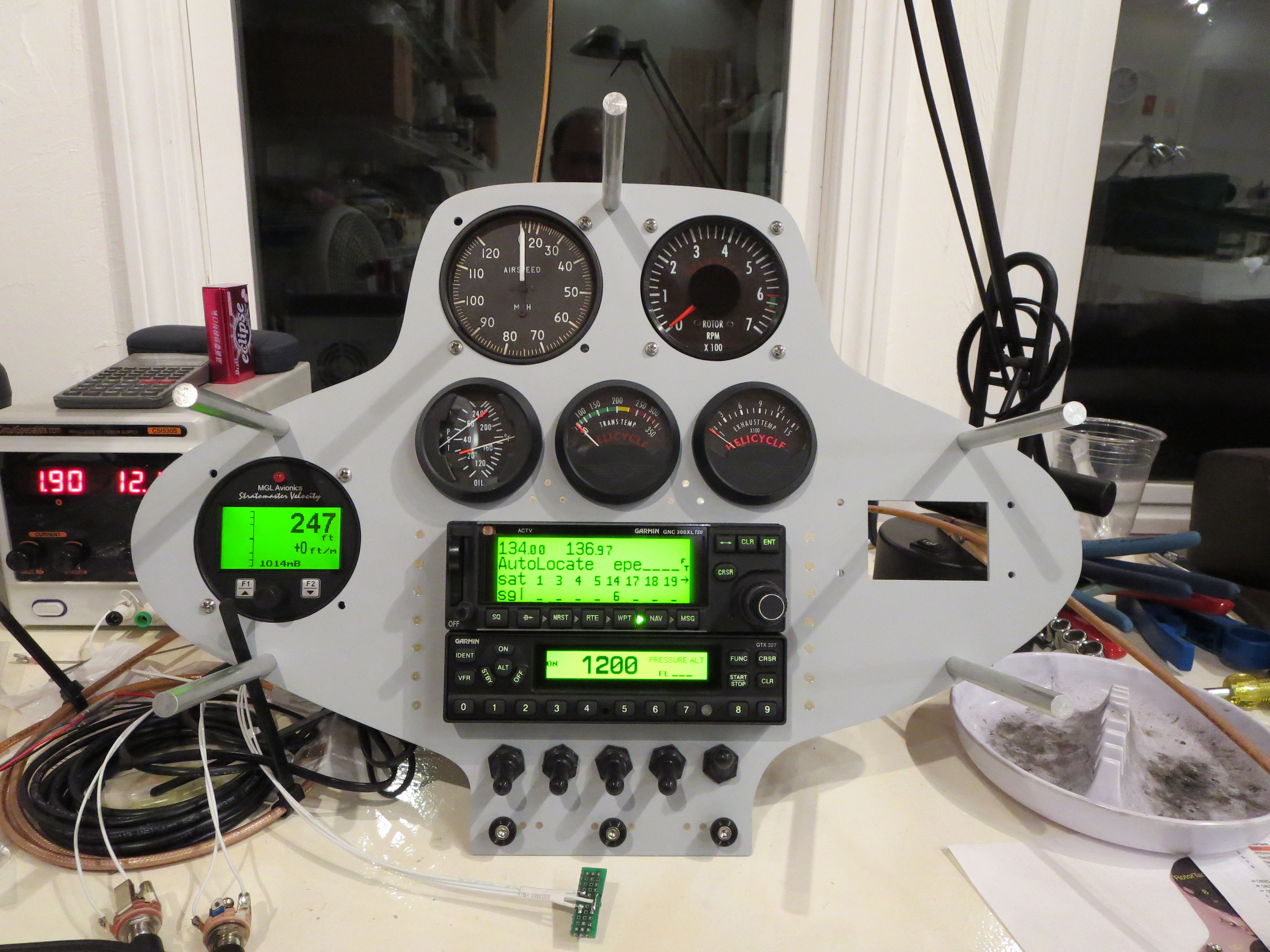
Ahhh the money shot! Everything powered up and is functioning OK as far as I can tell. I rigged up antennas and could send and receive over the radio to my handheld and get GPS position data accurately.
One thing that became immediately apparent is that the COMM draws HUGE current (comparatively) when transmitting versus receiving. Nominally the panel was drawing just under 2 amps, but it spiked to about 4 amps, and quickly dropped to 3 amps when transmitting. Wow.
Pre-Wiring
10/29/13 17:30 Filed in: All
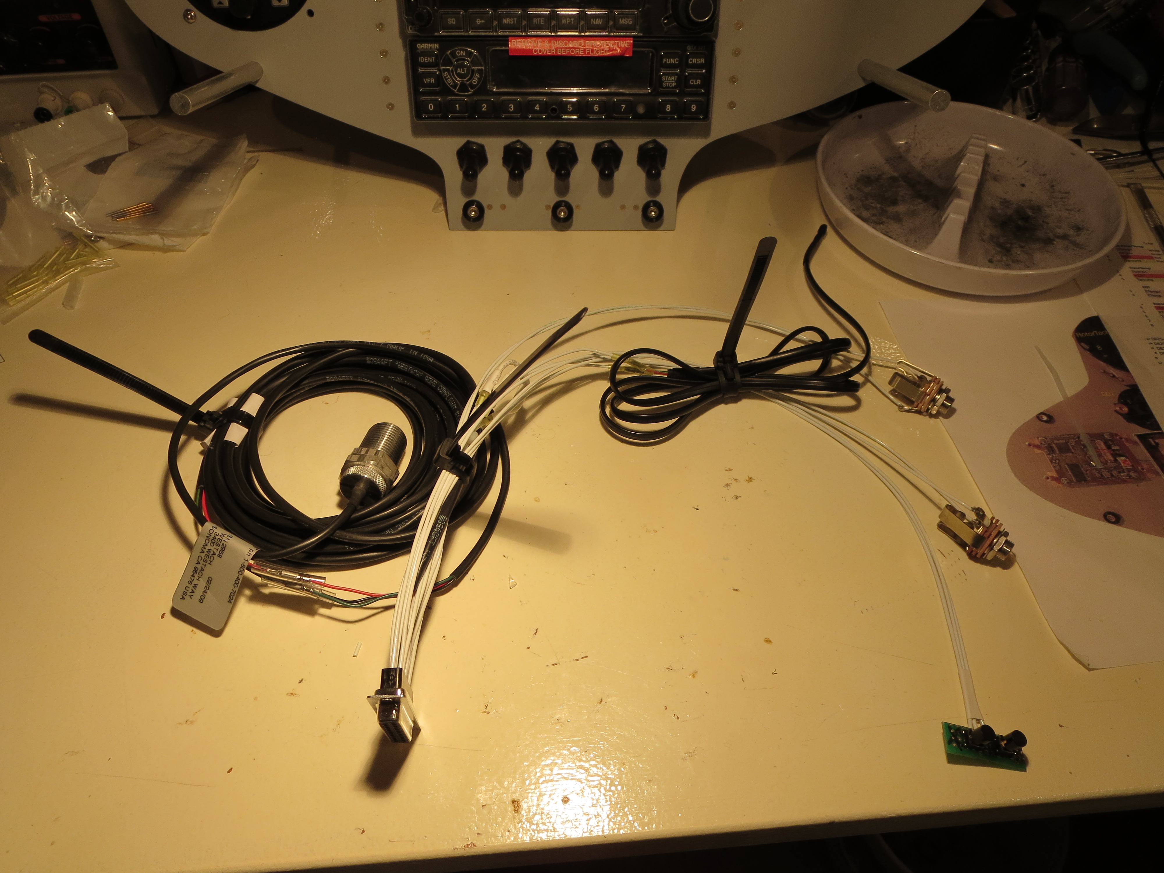
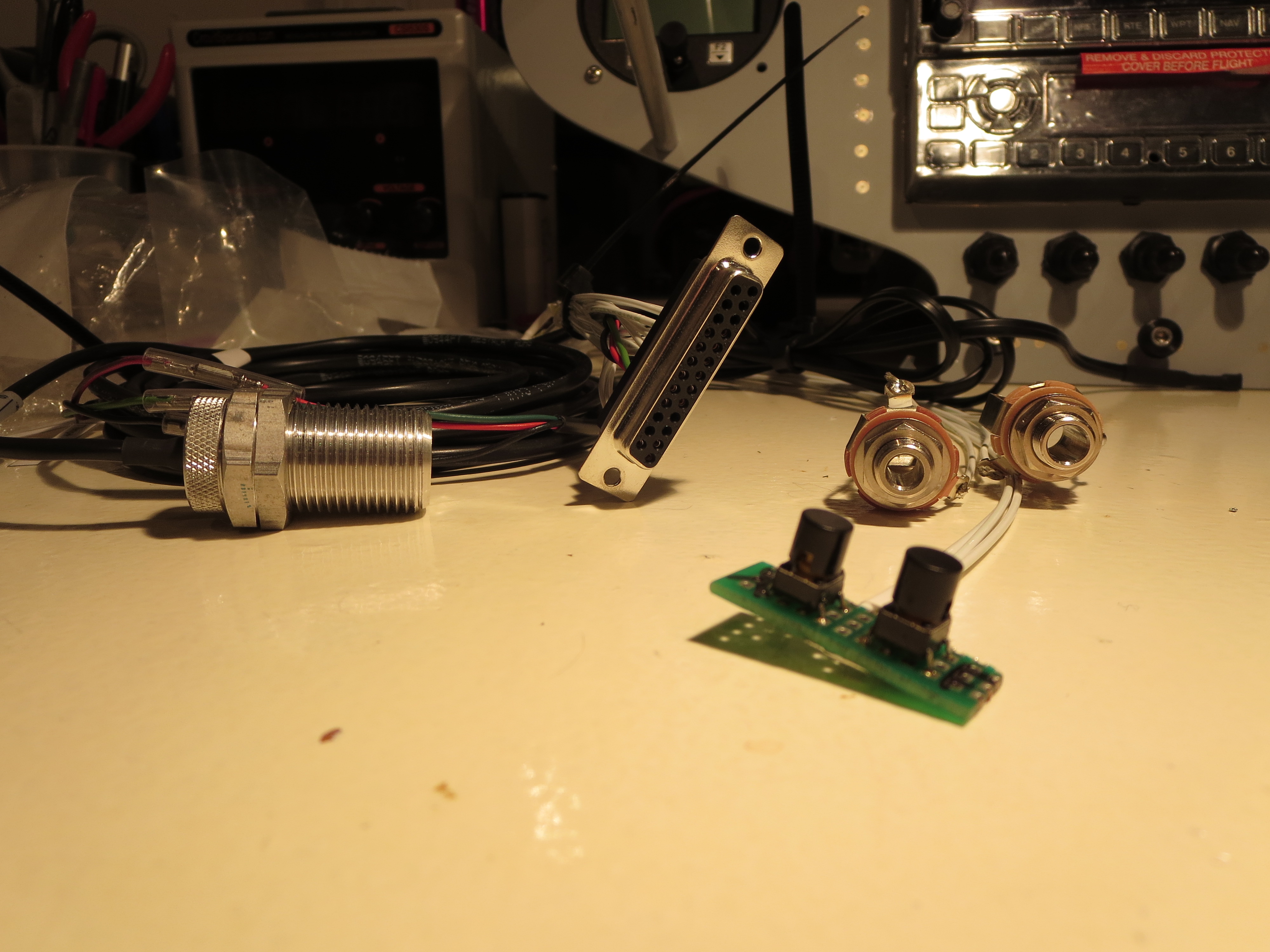
Starting in on the wiring of the panel. Have practiced crimping and roughly mapped out the wiring pathways. Power on one side of the avionics stack and a large 37 pin DSUB for all the signals that leave the panel on the other side.
Panel Cut & Delivered
04/01/13 17:23 Filed in: All
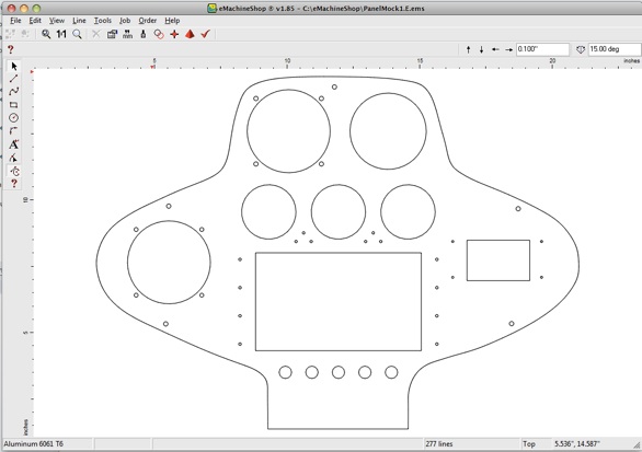
Panel Received. I discovered an online service called eMachineShop.com
This service will take a simple drawing and machine up a part for you. My method is to model the item in a “real” CAD system (in my case SpaceClaim), then import the drawing into their proprietary tool. You could do all your modeling in their tool, but it’s pretty primitive and yet another tool to learn. Select the material, and once it passes their design rule checks submit the part. A week later you get the item delivered. My panel cost me about $95 in 6061-T6 0.090” aluminum. I wanted some beef on the panel thickness to avoid having to add support structure for the planned avionics.
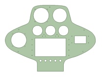
I took my aluminum “test fit” piece, traced it on graph paper, measured the points, and splined up the outline. Then I rough-modeled the instruments, shuffled them around and “cut” the holes. Everything is tight or slightly undersized so I can trim for a nice snug fit. As BJ says, it’s easier to remove metal than to add it back in.
And here is the finished item. It was returned in just over a week and fits perfectly. Some of the holes need trimming, but that was expected as I wanted a nice snug fit.
Here are the links to the rough DXF’s of my panel that I used to import into eMachineshop’s tools:
PanelMock1.A.dxf
LowerPanel.dxf
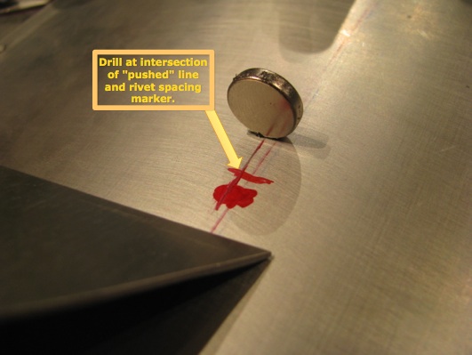
Ground Plane Mounting
08/20/12 17:09 Filed in: All
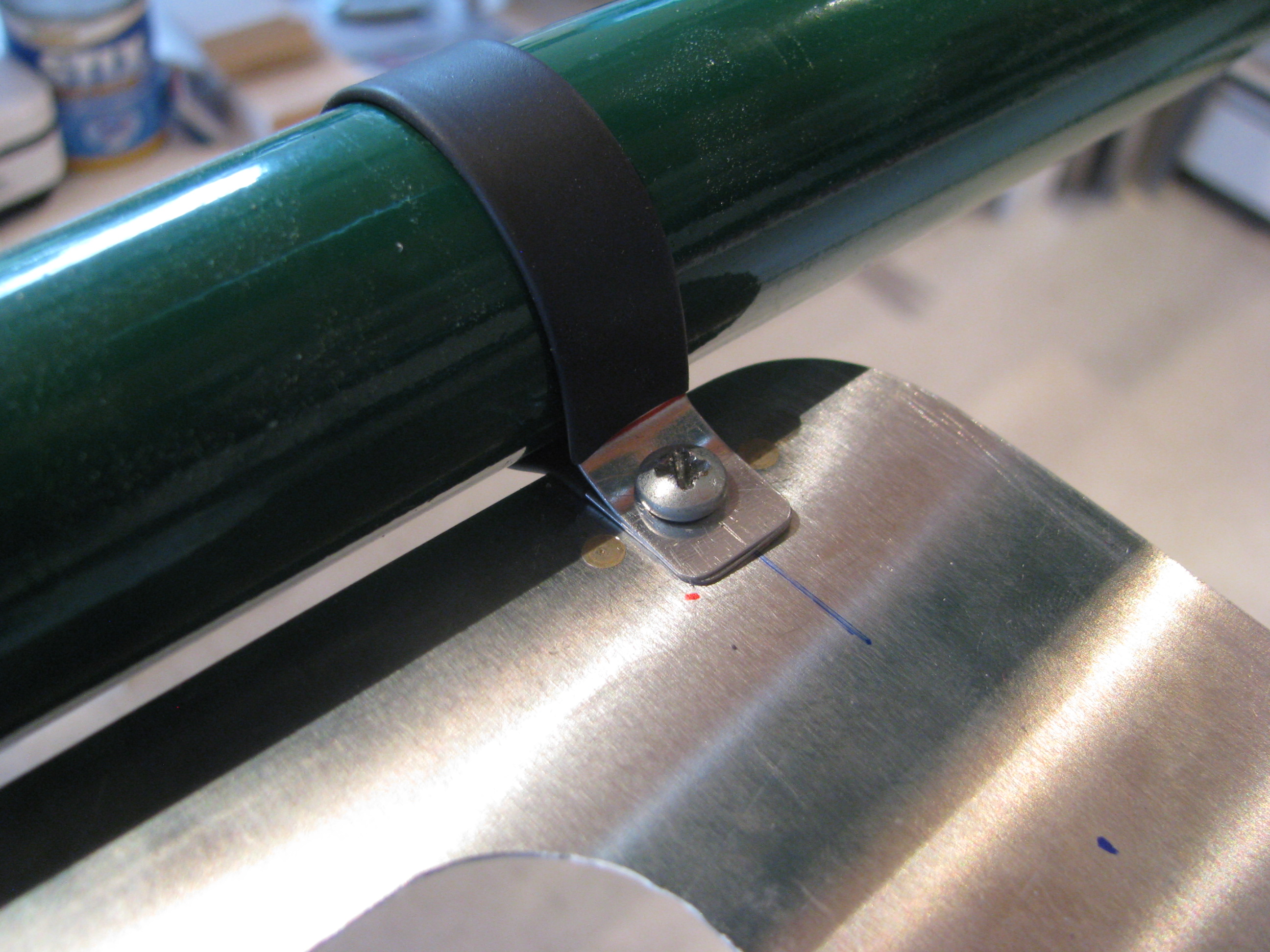
Completed the ground plane. I couldn’t see using Adel Clamps to secure it. Overkill. Instead I used little strips of 0.025 covered in shrink tube screwed through the ground plane to nutplates riveted to the bottom of the ground plane. Nice and tight, and it weighs next to nothing.
Ground Plane
07/24/12 16:39 Filed in: All
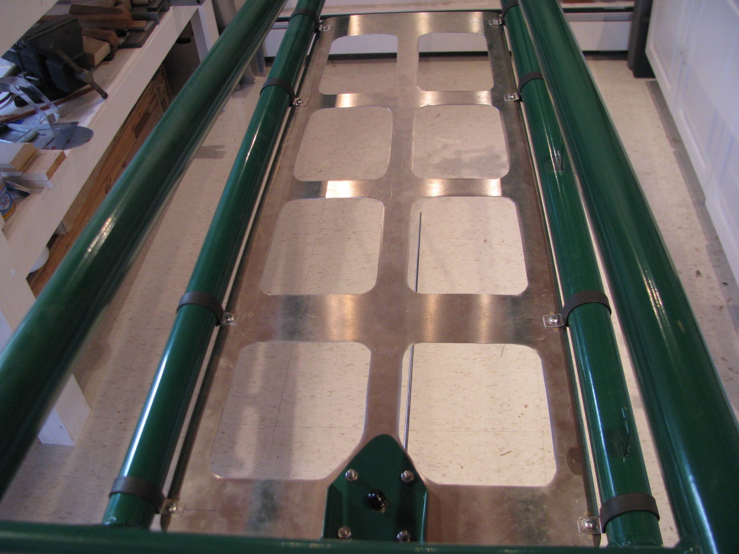
After having read Juan Rivera’s web site I decided that I would include a ground plane to improve the performance of the VHF communications antenna. The comm frequency range is 118 to 136 MHz. Therefore the 1/4 wavelength range is 21 to 25 inches. The sheet is 28 inches long. The longest diagonal opening is about 6.5 inches. No hole should be more than 1/10 wavelength (8.5 to 10 inches) so this should work well.
Cutting the sheet was a royal pain, but I didn’t want to just rivet strips together as the impedance across the joints would have adversely affected the RF performance of the ground plane. Drawing for the ground plane sheet is GroundPlane_B_072012.pdf.
Initial Panel Fabrication
06/03/12 16:31 Filed in: All
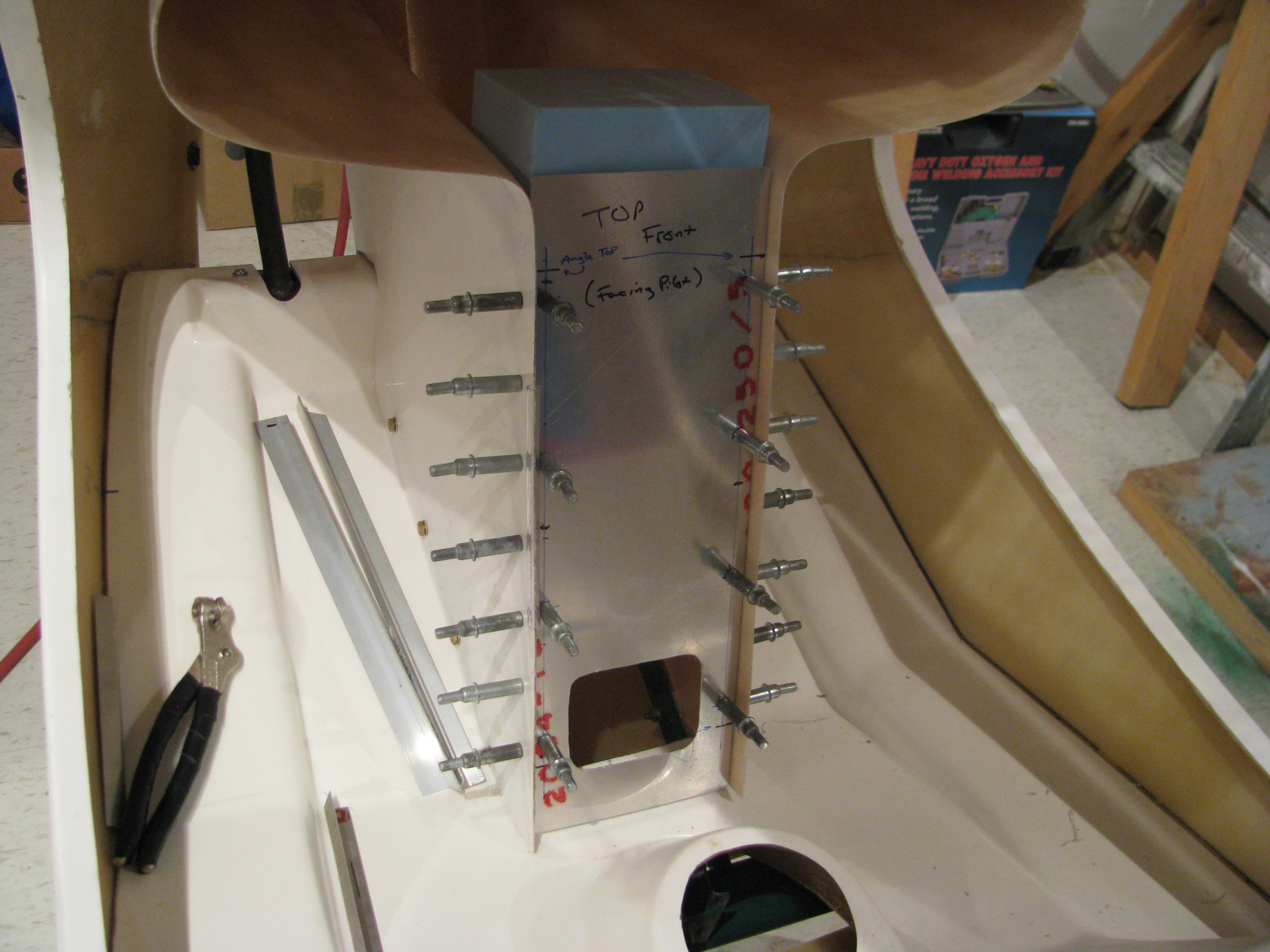
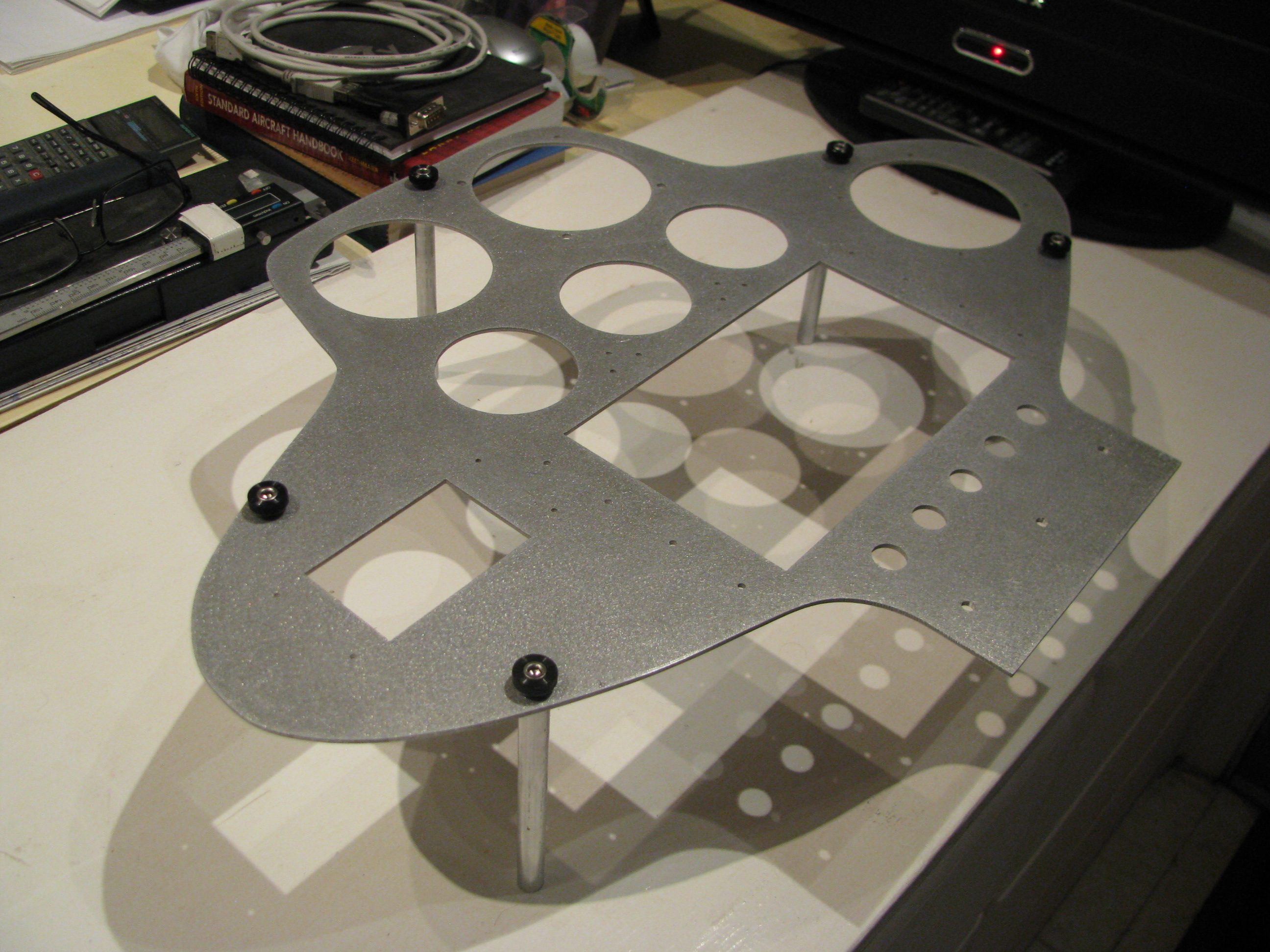
Fitting the lower instrument panel. The initial fitup is with a sacrificial aluminum sheet. Once everything is placed I will use it as a template to transfer the holes to the actual sheet to be used.
The hole is cut so I can get my hand in there and place a bracket on the pan to affix the panel on the lower edge, which should definitely strengthen things up. Screwing it in will be a pain since the cyclic riser is in the way, but not too bad with a 90 degree phillips.
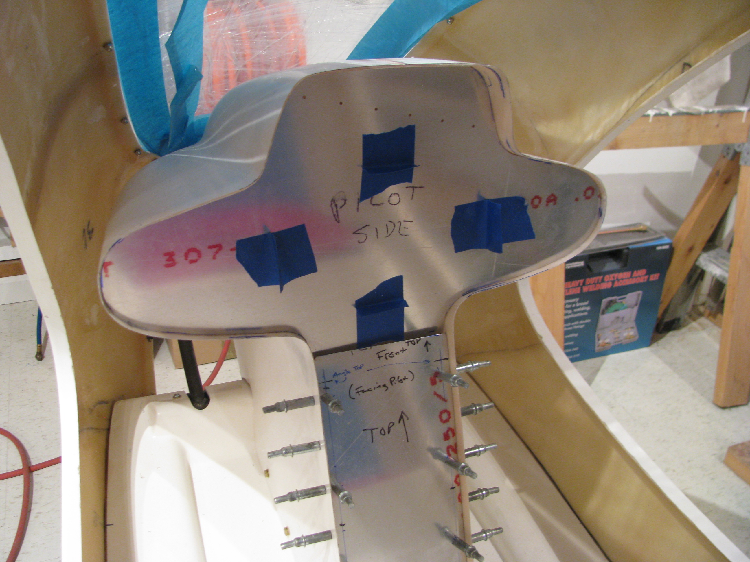
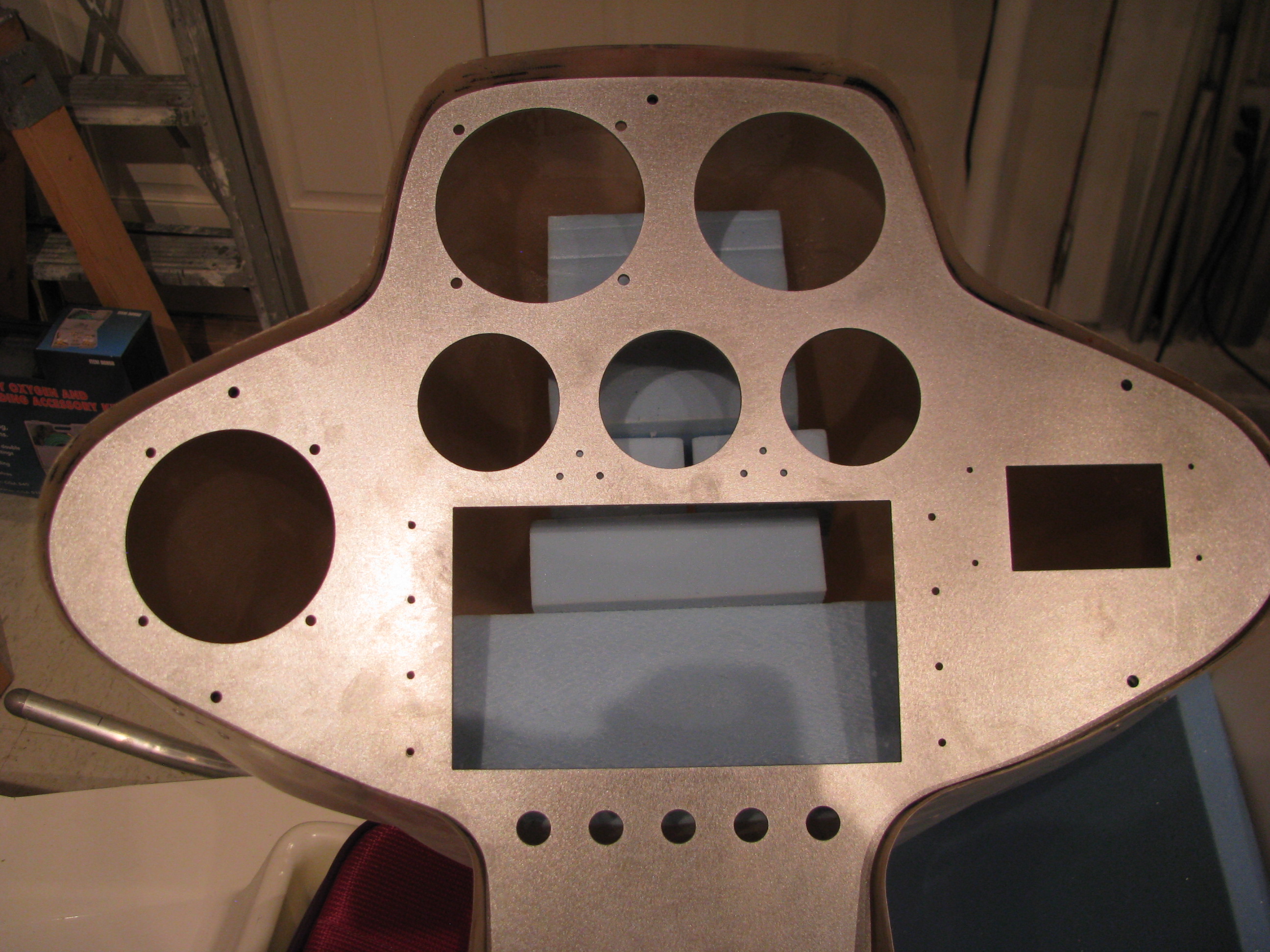
Initial cutout of the upper. This again is a sacrificial piece of aluminum. I wanted to see where I stand before messing around with the shape.
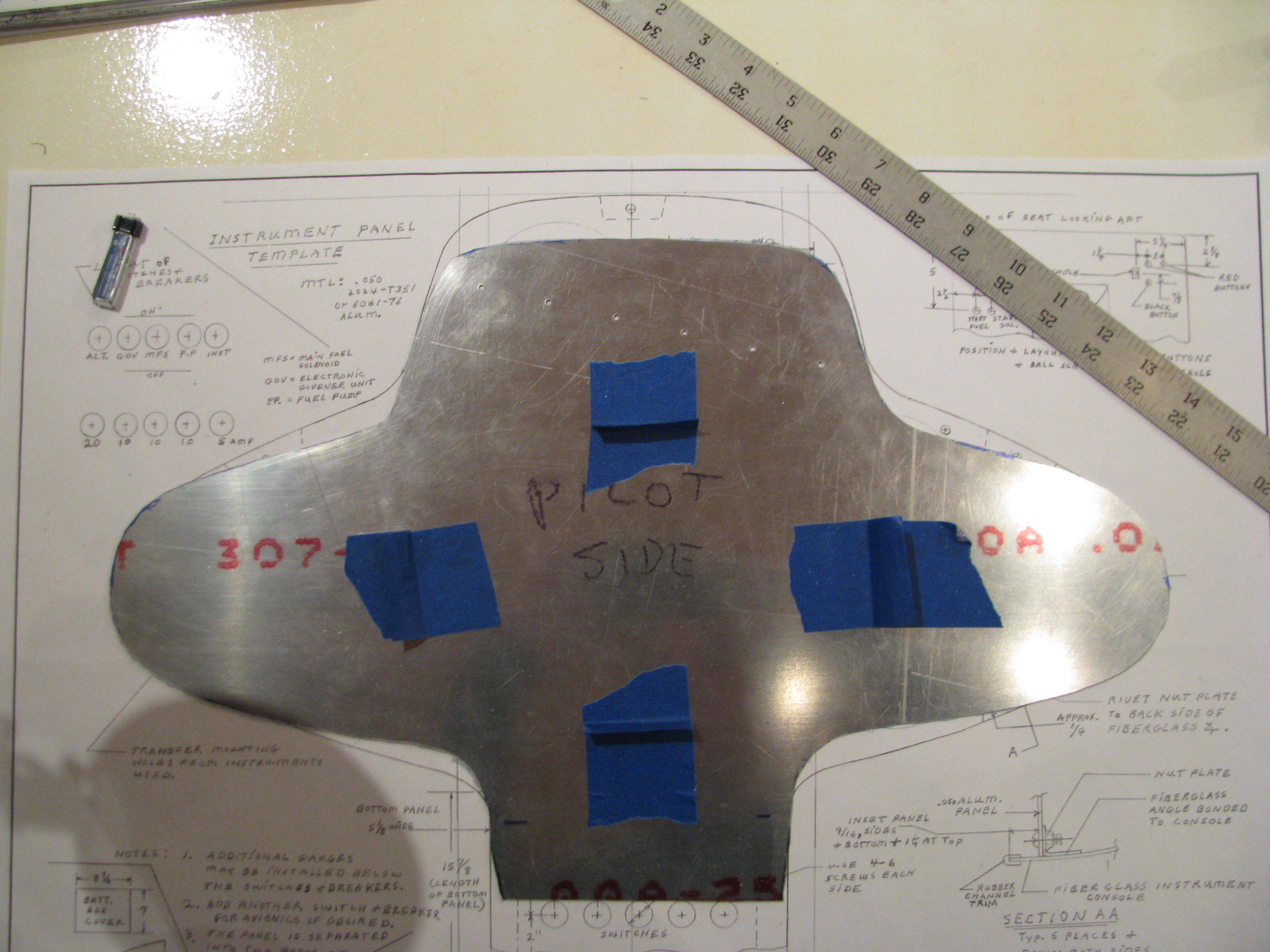
Obviously the upper instrument pod is flatter and narrower than the specified dimensions by a lot.
The drawing sheet shows an 18 3/8” width at the widest point. I am seeing almost an inch wider and and inch and a half “shorter” from the bottom to the top. I am going to have to shim the side lobes to get more vertical space and hopefully narrow it up some.
I’ll use some blue foam blocks to push the upper section up, but probably won’t get to the specified dimensions without really distorting the pod from it’s relaxed state, which I don’t want to do. The primary requirement is that the side lobes be large enough for a 3-1/8” instrument. Once that is close enough for me I will glass in the foam spacer blocks.
Instrument Panel Planning & Fitting
04/08/12 14:40 Filed in: All
Instruments planned for the upper pod:
TOP ROW: Airspeed Indicator, Rotor RPM
MIDDLE ROW: Altitude, temp gauges, Flow Level/Flow, Vertical Speed
BOTTOM: GPS/COMM , Transponder, Compass
Lower Section: Switches, Engine RPM, Breakers
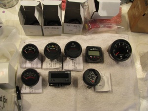
All but one of these are provided with the kit; Voltage, Transmission Temp, Hour Meter, Flow Flow (I supplied), Tachometer, Turbine Exhaust Temp, Engine Tach, and Oil Temp and Pressure.
Leftover from my RV8A project is a Garmin GNC300XL GPS/COMM and a GTX327 transponder.
Left to purchase is an AS indicator, Altimeter, and VSI.
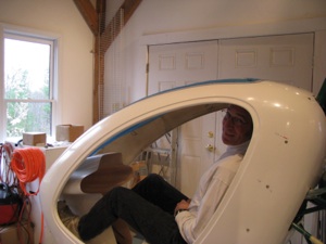
Checking the instrument pod positioning. And... making helicopter noises. One of those FAA “builder” pictures.
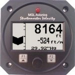
I ordered a Falcon 0-120MPH airspeed indicator and decided to try something a little different for the altitude. I ordered an MGL combined digital Altimeter and VSI.
Unlike fixed wing flying, I find myself really only relying on the altimeter around airports and airspace in a helicopter. You’re flying is so low and slow that visual reference for altitude is pretty accurate. The VSI bar looks quite attention-getting, which is the important thing. We’ll see how this works.
Instrument Pod Bracket
06/19/11 22:15 Filed in: All
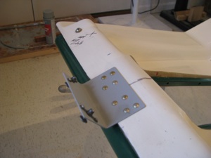
The front bracket is riveted on to stabilize the instrument pod. I have a lot of solid rivets in stock from my RV project and use them wherever possible instead of pop rivets.