
TailRotor
CNC Routed Parts
01/26/15 21:43 Filed in: All
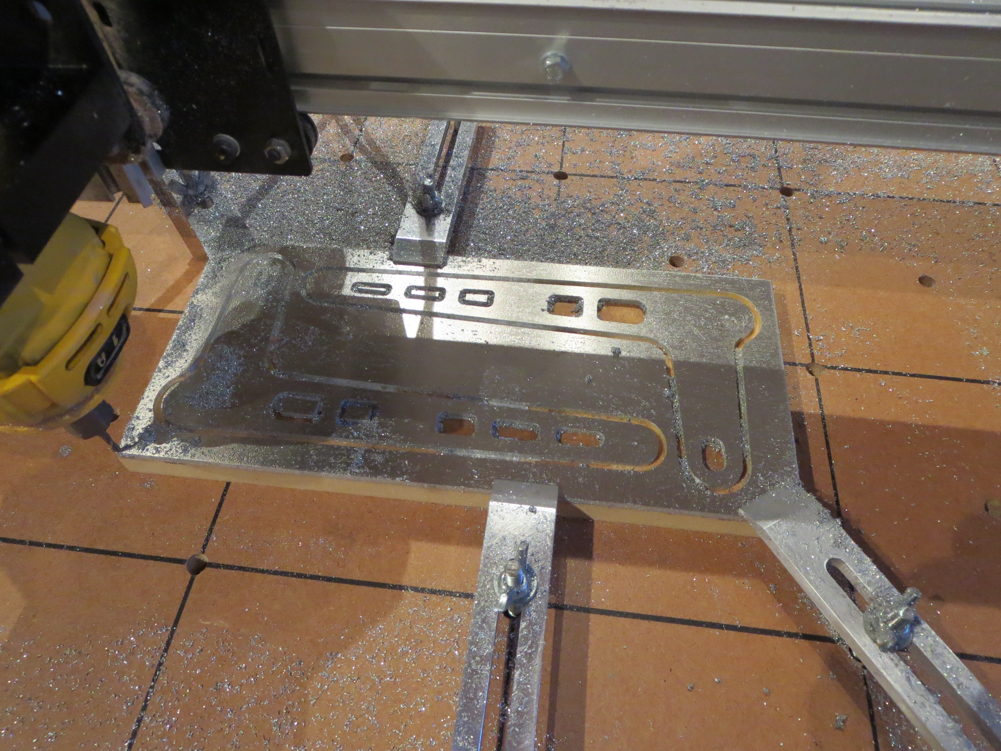
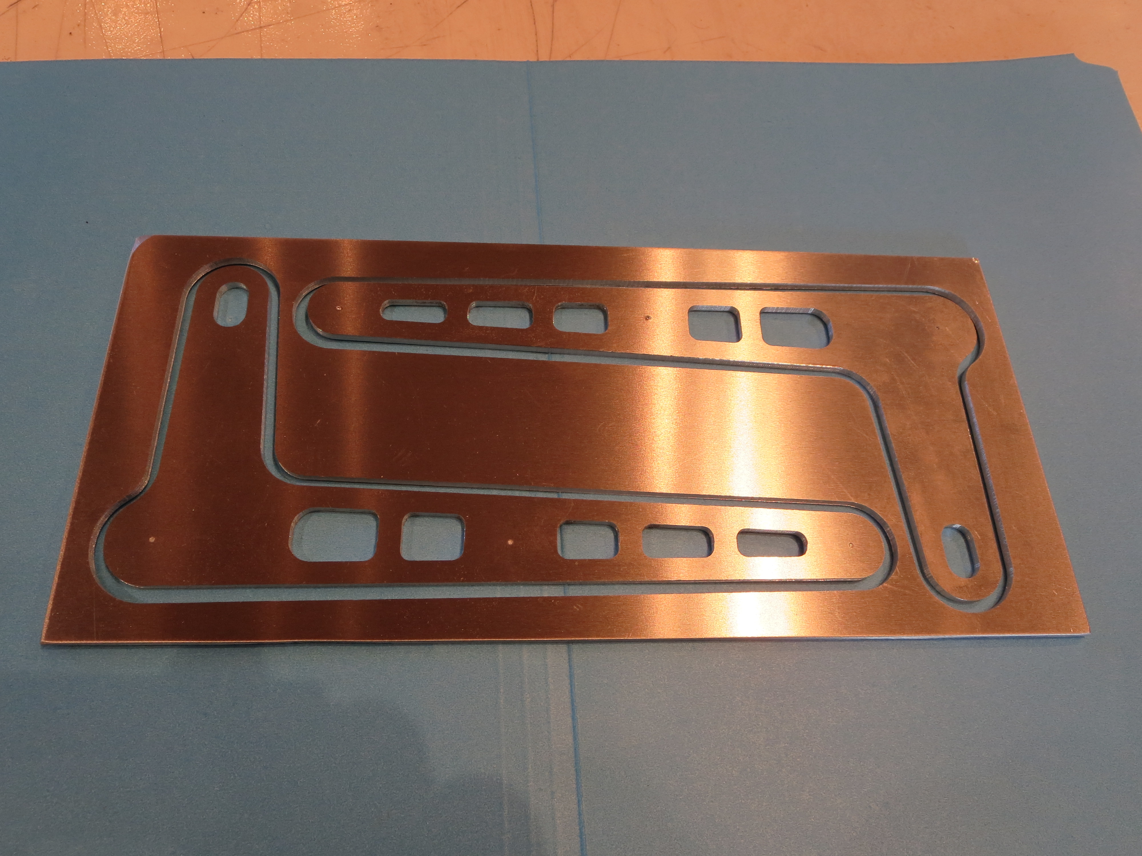
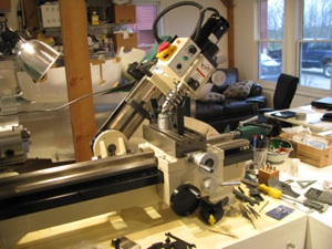
After much diddling and fiddling I am finally able to achieve a good deal of accuracy from my CNC router. While great for engraving and shaping wood, it is challenged for metal.
Fundamentally it lacks the stiffness for super-high accuracy or extremely clean cuts. It is belt driven and belts stretch. If you grab the carriage and wiggle it, you can move it back and forth maybe 10-15 mils. I have braced the metal frame, but fundamentally it is limited by that design compromise.
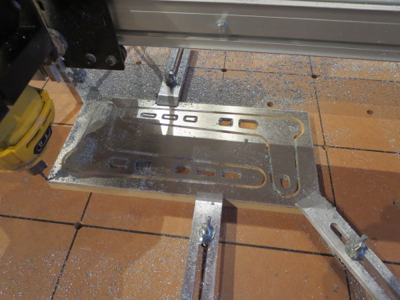
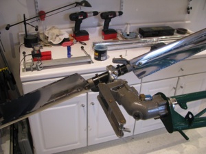
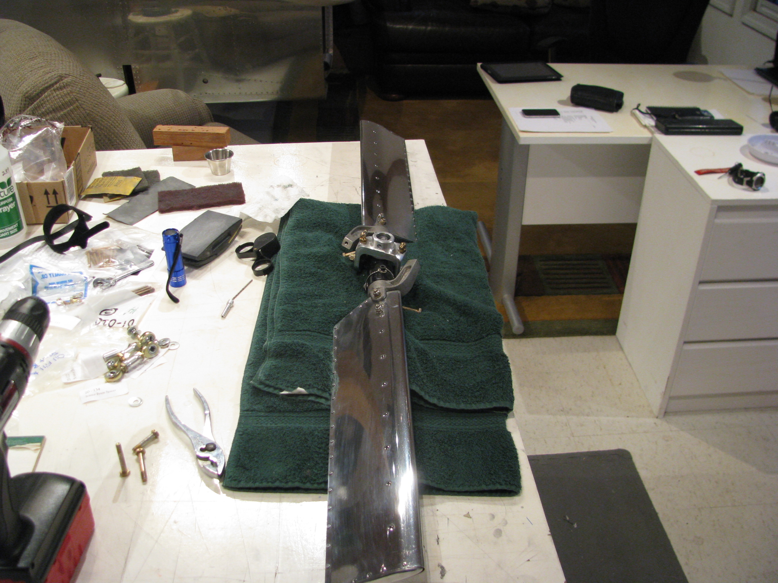
Still, for some sorts of things it is fine. I have just cut a new set of tail rotor control scissors. They are cut just as accurately as the hand cut ones I did earlier. The two pieces are nearly an exact match. The holes are drilled on the drill press as routing those holes would be insufficient accuracy. The routed slots for the steel bushings ARE at least as accurate as the hand cut ones.
I am satisfied with the results. Perhaps I will later try a new TR walking beam for pedal attach, The pieces I can fabricate are certainly straight, and light.
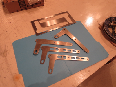
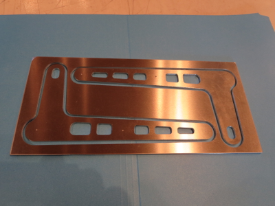
Old and new compared.
Fundamentally it lacks the stiffness for super-high accuracy or extremely clean cuts. It is belt driven and belts stretch. If you grab the carriage and wiggle it, you can move it back and forth maybe 10-15 mils. I have braced the metal frame, but fundamentally it is limited by that design compromise.
Still, for some sorts of things it is fine. I have just cut a new set of tail rotor control scissors. They are cut just as accurately as the hand cut ones I did earlier. The two pieces are nearly an exact match. The holes are drilled on the drill press as routing those holes would be insufficient accuracy. The routed slots for the steel bushings ARE at least as accurate as the hand cut ones.
I am satisfied with the results. Perhaps I will later try a new TR walking beam for pedal attach, The pieces I can fabricate are certainly straight, and light.

Old and new compared.
Received Fixed Bearing
05/26/12 13:36 Filed in: All
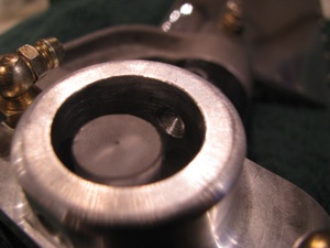
After more than a month I received my rebuilt tail rotor slider bearing from Eagle. Smooth. I can now finish up the tail rotor assembly.
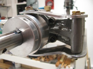
Mounting TR Assy
03/24/12 13:35 Filed in: All
The actual kit I have (build 5) differs a little from what you see in the videos. I am assuming things have improved and the differences are due to improvements over time. One area is the tail rotor attachment. BJ makes reference to prick punch marks and precision fitment. In my case the yoke is drilled on one side only and is quite a bit undersize for an AN4 Bolt.
There are no matching prick punch marks.
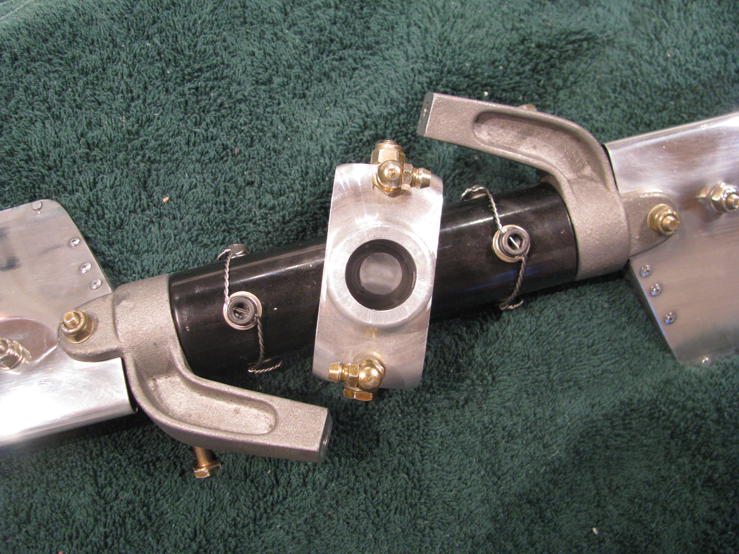
Here is the business end of the tail rotor hub looking into the yoke. The plastic piece in the center is the “flapping restraint” plug. The allen bolts have been drilled and safety wired.
Looking into the yoke you can see the undrilled side. I searched the builders group and contacted Keith Southard whose kit was of the same vintage. He had the same situation and recommended a procedure for finish drilling this hole precisely with no slop.
The builder’s site is a great resource. Collectively there is a ton of information assembled and very knowledgable folks who are pretty responsive are active on it.
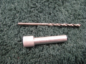
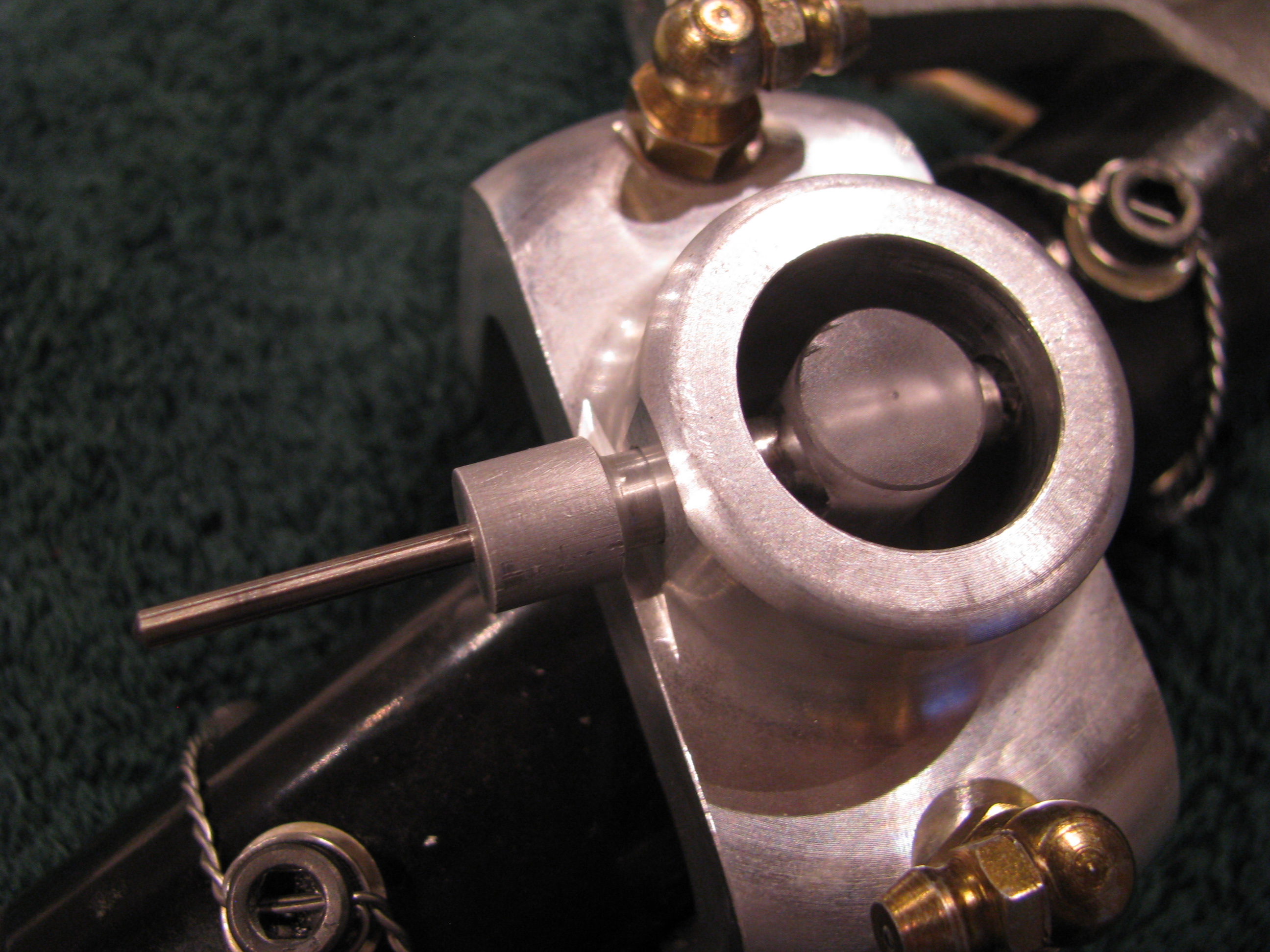
Start by making a drill bushing so a pilot can be drilled on the unfinished yoke side that will be perfectly centered. I chucked up an aluminum rod and lathed it down until it just barely and snugly fit in the hole on the drilled side. Then center bore a hole in the bushing for the pilot drill.
True to form, I messed up the first one, so I gave it a gentle chamfer and will use it as a drift to get everything lined up before employing the bushing and drilling for real.
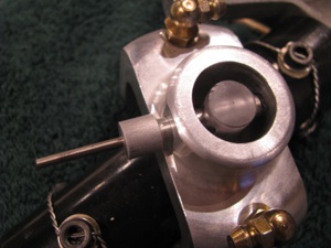
The idea is that I will drill the far side yoke hole with the drill bushing in assembly and then open it up slowly.
The final couple of steps, including the reaming, if necessary, will be done in assembly so there is absolutely no slop. I will procure a collection of the correct length AN4 bolts including some “close fit” bolts so I have a selection to choose from . It is surprising how different bolts in the same bag can have different diameters by +/- a couple of a mils.
I also purchased kit of Nuvite Aluminum polish after reading Juan Rivera’s site and seeing his results. My plan is to polish the TR (no paint) as well as the TR drive shaft, main blades, and perhaps skids.
Now I am no expert. I just got the stuff. There are several different grades from the coarsest to the finest.
It doesn’t take a lot of brainpower, but it does take a lot of patience to get results. This is my first pass on the TR blades. It already looks better than anything I’ve ever polished before and I am sure I will repeat the sequence after all the handling of the TR is complete - so it will only get better.

Now I don’t think I’ll ever be as patient as Juan in getting the finish he shows on his web site, but it’ll still look good.
Polishing seems to have this bi-modal perception. You can get it looking shiny and very good. Stopping there would be fine. THEN , you decide to get mirror-like results and it’ll look like crap because once part of the surface shines up like a mirror, all the minor scratches and striations in the other areas become evident until the entire surface is perfect.
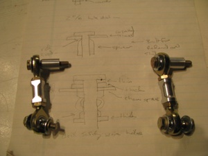
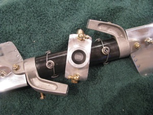
TR pitch link hardware. I blindly followed BJs instructions and cut 11/16 off the threads on the rod ends. You could probably leave another 1/16th or two on the ends (more threads to engage) as there is no way they will interfere with each other when screwed all the way in to the aluminum couplers.
I find that I am often making little sketches as I watch the videos (over and over) to have something to refer to in the shop.
Drilling the safety wire holes in the slider would be a bit of a challenge without the mill. This is the first time I have ever angled the head over. The bearing block is then clamped to the surface in such a way that there is no side load on the bearing itself through the use of 3 large fender washers underneath the inner race.
As in most machining operations, the machine setup and work holding take 90% of the time. The actual metal cutting is but a few seconds.

The outer race is supported underneath with some blocks so there is no side load on the bearing. A center drill is absolutely necessary for its stiffness. Drill just deep enough so that a normal bit will not jump out.
The first hole was a mess, the second better, and by the fourth it was perfect. I’m sure my second helicopter would be absolute perfection.
TR pre-assembled. Couldn’t resist spinning it around.
When I did this, however, I noticed that the slider bearing was not spinning cleanly. The bearing is defective and “ticks” as it spins. You can feel the “hitches” when you spin it by hand on the bench. I called Blake and he agreed that it didn’t sound right. It’s on its way back to Eagle to have a new one pressed in.
There are no matching prick punch marks.
Here is the business end of the tail rotor hub looking into the yoke. The plastic piece in the center is the “flapping restraint” plug. The allen bolts have been drilled and safety wired.

Looking into the yoke you can see the undrilled side. I searched the builders group and contacted Keith Southard whose kit was of the same vintage. He had the same situation and recommended a procedure for finish drilling this hole precisely with no slop.
The builder’s site is a great resource. Collectively there is a ton of information assembled and very knowledgable folks who are pretty responsive are active on it.

Start by making a drill bushing so a pilot can be drilled on the unfinished yoke side that will be perfectly centered. I chucked up an aluminum rod and lathed it down until it just barely and snugly fit in the hole on the drilled side. Then center bore a hole in the bushing for the pilot drill.
True to form, I messed up the first one, so I gave it a gentle chamfer and will use it as a drift to get everything lined up before employing the bushing and drilling for real.
The idea is that I will drill the far side yoke hole with the drill bushing in assembly and then open it up slowly.
The final couple of steps, including the reaming, if necessary, will be done in assembly so there is absolutely no slop. I will procure a collection of the correct length AN4 bolts including some “close fit” bolts so I have a selection to choose from . It is surprising how different bolts in the same bag can have different diameters by +/- a couple of a mils.
I also purchased kit of Nuvite Aluminum polish after reading Juan Rivera’s site and seeing his results. My plan is to polish the TR (no paint) as well as the TR drive shaft, main blades, and perhaps skids.
Now I am no expert. I just got the stuff. There are several different grades from the coarsest to the finest.
It doesn’t take a lot of brainpower, but it does take a lot of patience to get results. This is my first pass on the TR blades. It already looks better than anything I’ve ever polished before and I am sure I will repeat the sequence after all the handling of the TR is complete - so it will only get better.

Now I don’t think I’ll ever be as patient as Juan in getting the finish he shows on his web site, but it’ll still look good.
Polishing seems to have this bi-modal perception. You can get it looking shiny and very good. Stopping there would be fine. THEN , you decide to get mirror-like results and it’ll look like crap because once part of the surface shines up like a mirror, all the minor scratches and striations in the other areas become evident until the entire surface is perfect.
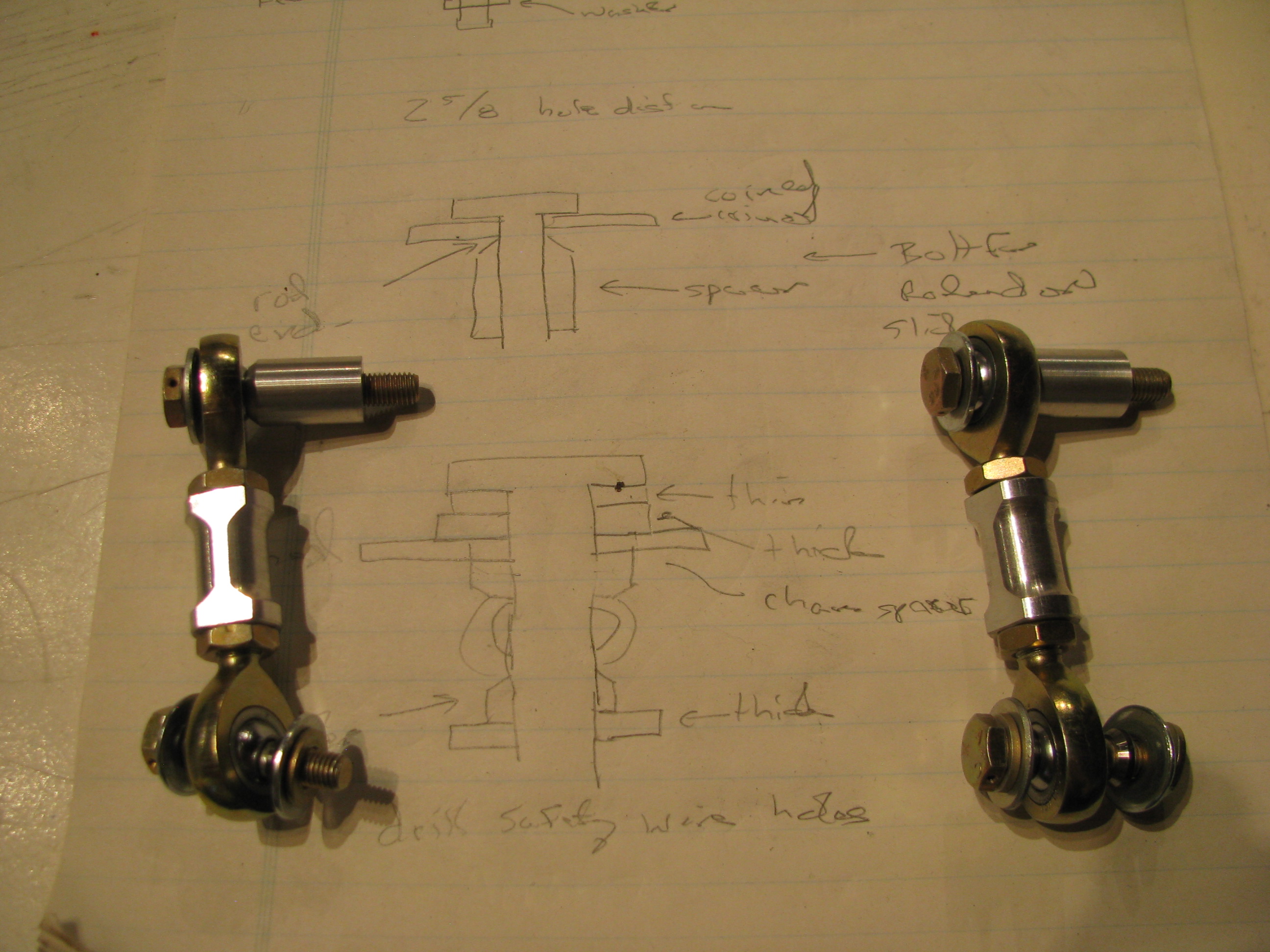
TR pitch link hardware. I blindly followed BJs instructions and cut 11/16 off the threads on the rod ends. You could probably leave another 1/16th or two on the ends (more threads to engage) as there is no way they will interfere with each other when screwed all the way in to the aluminum couplers.
I find that I am often making little sketches as I watch the videos (over and over) to have something to refer to in the shop.
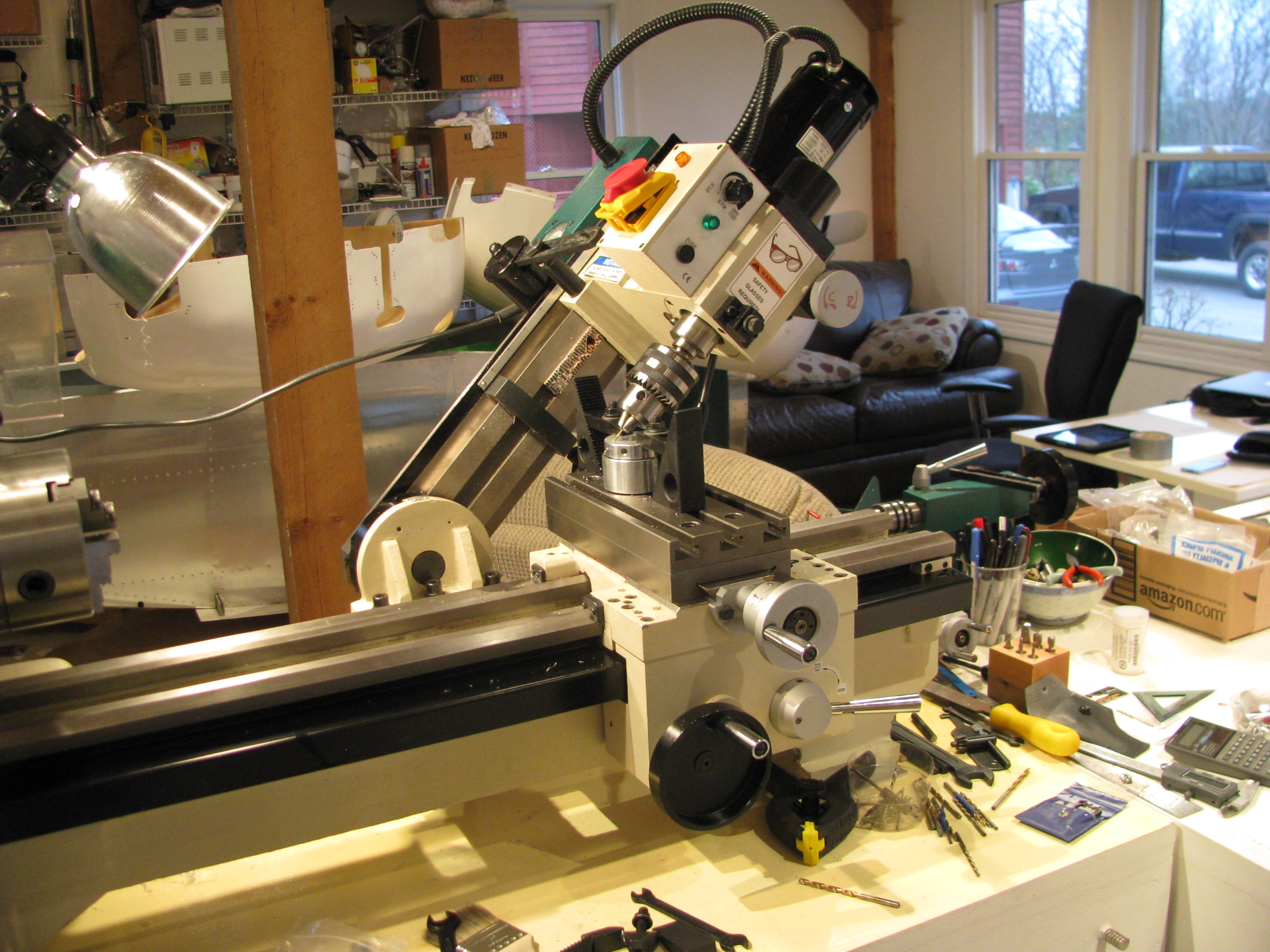
Drilling the safety wire holes in the slider would be a bit of a challenge without the mill. This is the first time I have ever angled the head over. The bearing block is then clamped to the surface in such a way that there is no side load on the bearing itself through the use of 3 large fender washers underneath the inner race.
As in most machining operations, the machine setup and work holding take 90% of the time. The actual metal cutting is but a few seconds.
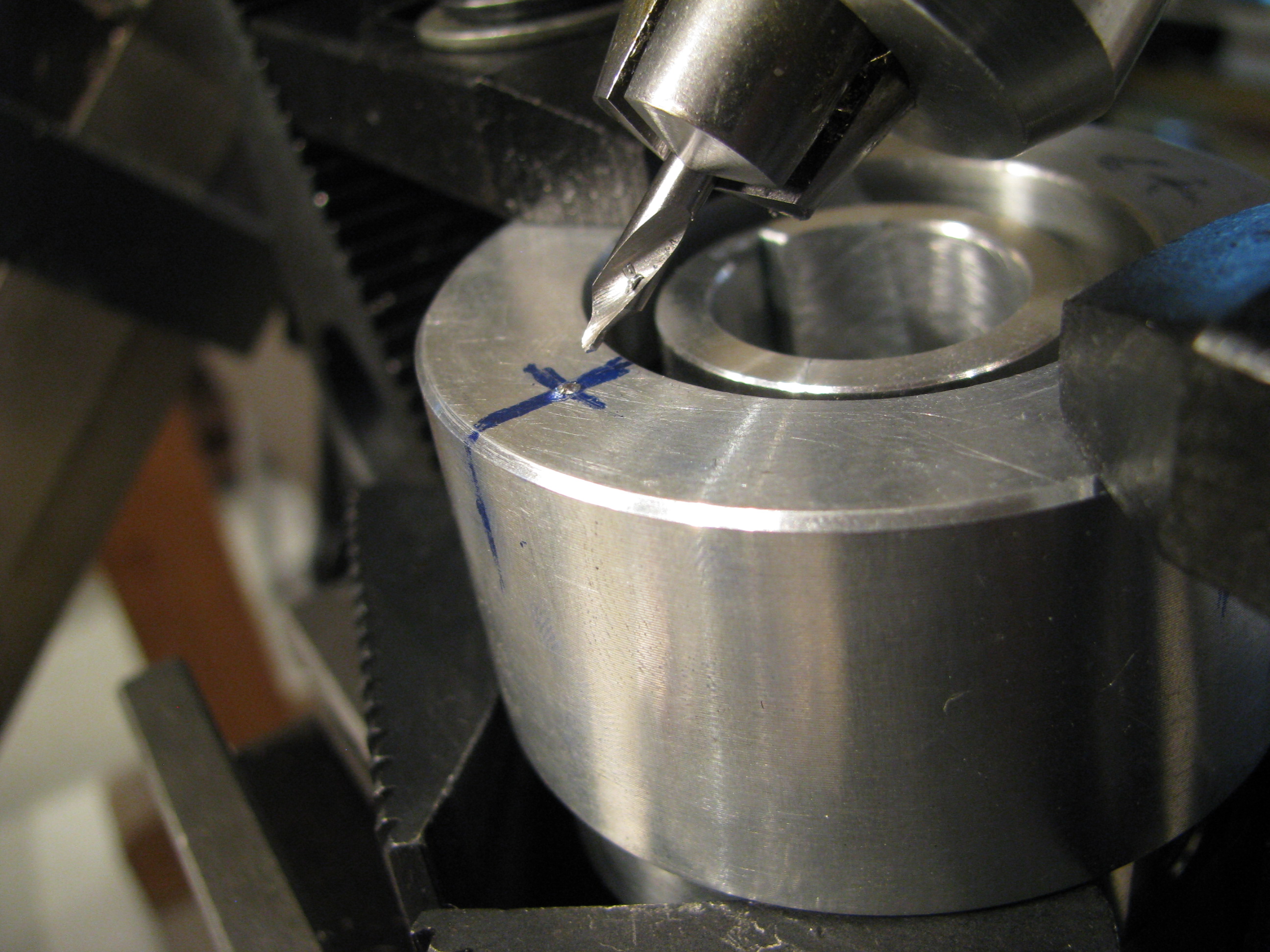
The outer race is supported underneath with some blocks so there is no side load on the bearing. A center drill is absolutely necessary for its stiffness. Drill just deep enough so that a normal bit will not jump out.
The first hole was a mess, the second better, and by the fourth it was perfect. I’m sure my second helicopter would be absolute perfection.

TR pre-assembled. Couldn’t resist spinning it around.
When I did this, however, I noticed that the slider bearing was not spinning cleanly. The bearing is defective and “ticks” as it spins. You can feel the “hitches” when you spin it by hand on the bench. I called Blake and he agreed that it didn’t sound right. It’s on its way back to Eagle to have a new one pressed in.
Beacon Strobe
02/10/13 13:34 Filed in: All
Working my way forward, I knew I wanted a strobe of some form. Traditional commercial strobes are expensive, heavy, and generate several hundred volt spikes that have to be well contained or will play hell with your electronics and radio.
LED technology has made leaps and bounds in recents years. I decided to build my own strobes based on some new 900 Lumen CRE LEDs. That’s 900 lumens each. My old-fashioned living-room flood light bulbs are each 800 lumens at 90watts, just to put that in perspective. According to the spec sheet you can get almost twice that light per device if it is not continuous duty by overdriving the current.
So six of these LEDs with a peak of 1800 lumens each gets us about 10,000 lumens. The trick is handling the current. At 4amps per device that’s 24 amps. You certainly don’t want to switch that on and off directly from the battery. The current loop in the ship’s wiring would induce its own set of problems.
So to deal with that I developed a little circuit that charges up a capacitor bank, discharges through the LEDs then charges up again. The sequence is a 25millisecond flash, pause 100 milliseconds, another 25 millisecond flash, then pause 1.5 seconds, repeat forever. The caps charge during that 1.5second delay and therefore the average current to the whole strobe unit is 0.3A at 12V and should be very easy on the rest of the ship’s systems.
Best of all, the thing weighs next to nothing. I haven’t measured, but it can’t be more than a couple of ounces.
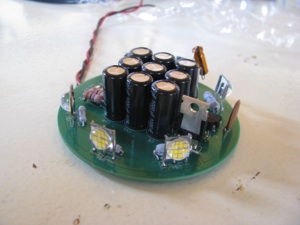
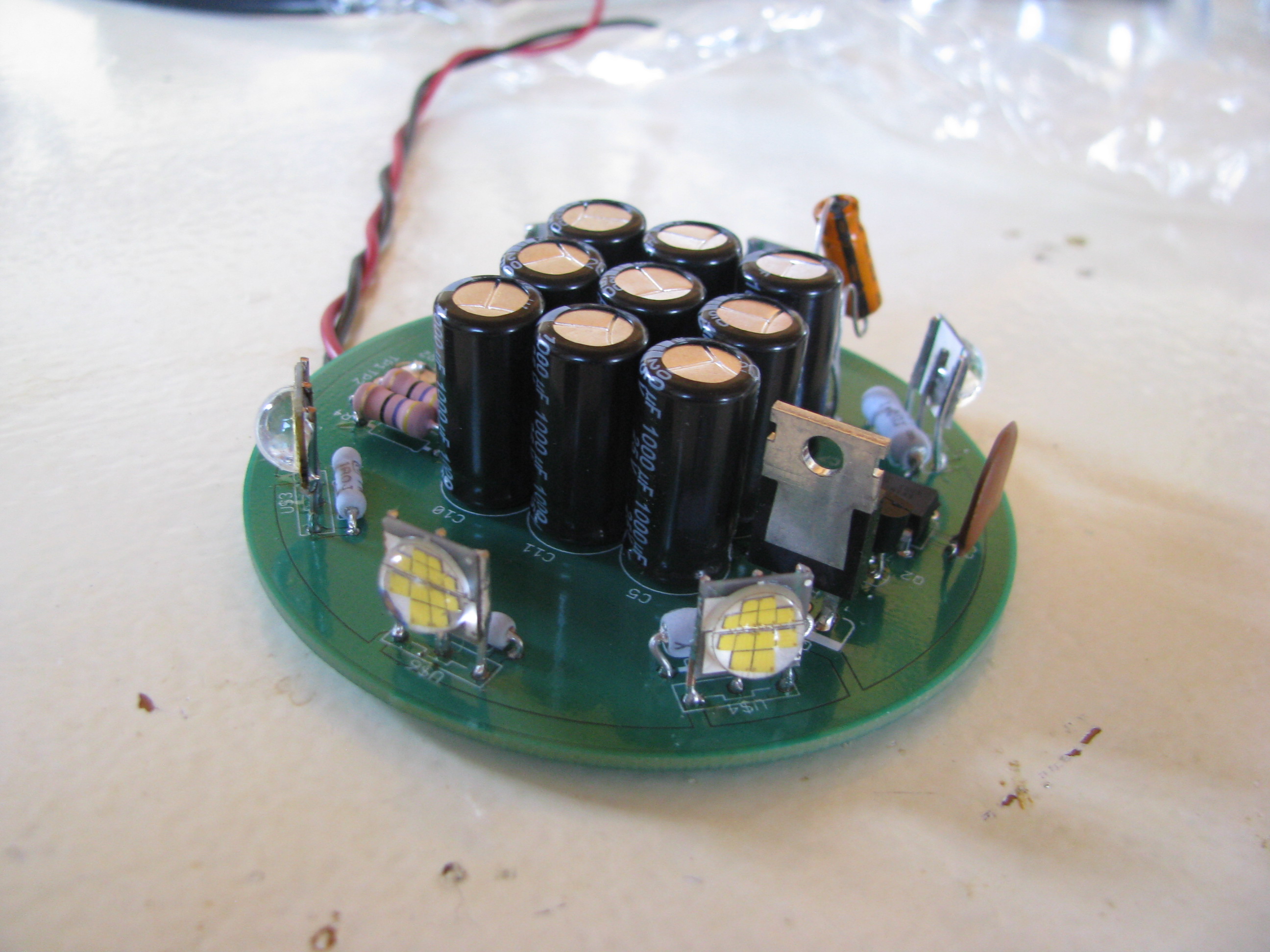
Here’s the circuit. Ignore the two capacitors dangling in the breeze. They are bulk and decoupling for the ATTiny85 microcontroller that controls the sequence. I forgot to order SMT caps from Digikey and will replace those before buttoning it up.
For those interested the schematic can be seen at Strobe_A.pdf. If you do something like this, pay attention to the ripple current rating of the capacitors. Layout is Strobe_A_top.pdf.
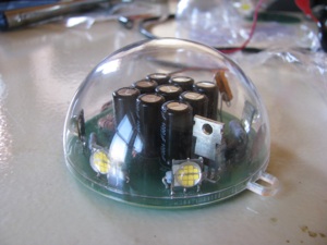
The PCB was sized to fit in a polycarbonate sphere bought at a craft store. The shell is designed to be used as a homemade christmas ornament.
I used Sunstone circuits “Value Proto” service for my PCB. This is a very cheap PCB fab process that uses unused panel space on other designs going through to keep your individual cost down. The down side is that the lead time can be long since they have to wait for a design with spare panel space - but hey, it’s very, very cheap.
If you do something like this, bear in mind that if the lights were left ON continuously (not blinking) it would heat up quickly and destroy itself. This circuit only works if the duty cycle (lights on period) is very, very low. I have left it running for days blinking along with no problems and cool to the touch, with flash pulses that are retina-melting. If you look at it directly by mistake you will see spots for an hour.
LED technology has made leaps and bounds in recents years. I decided to build my own strobes based on some new 900 Lumen CRE LEDs. That’s 900 lumens each. My old-fashioned living-room flood light bulbs are each 800 lumens at 90watts, just to put that in perspective. According to the spec sheet you can get almost twice that light per device if it is not continuous duty by overdriving the current.
So six of these LEDs with a peak of 1800 lumens each gets us about 10,000 lumens. The trick is handling the current. At 4amps per device that’s 24 amps. You certainly don’t want to switch that on and off directly from the battery. The current loop in the ship’s wiring would induce its own set of problems.
So to deal with that I developed a little circuit that charges up a capacitor bank, discharges through the LEDs then charges up again. The sequence is a 25millisecond flash, pause 100 milliseconds, another 25 millisecond flash, then pause 1.5 seconds, repeat forever. The caps charge during that 1.5second delay and therefore the average current to the whole strobe unit is 0.3A at 12V and should be very easy on the rest of the ship’s systems.
Best of all, the thing weighs next to nothing. I haven’t measured, but it can’t be more than a couple of ounces.
Here’s the circuit. Ignore the two capacitors dangling in the breeze. They are bulk and decoupling for the ATTiny85 microcontroller that controls the sequence. I forgot to order SMT caps from Digikey and will replace those before buttoning it up.
For those interested the schematic can be seen at Strobe_A.pdf. If you do something like this, pay attention to the ripple current rating of the capacitors. Layout is Strobe_A_top.pdf.

The PCB was sized to fit in a polycarbonate sphere bought at a craft store. The shell is designed to be used as a homemade christmas ornament.
I used Sunstone circuits “Value Proto” service for my PCB. This is a very cheap PCB fab process that uses unused panel space on other designs going through to keep your individual cost down. The down side is that the lead time can be long since they have to wait for a design with spare panel space - but hey, it’s very, very cheap.
If you do something like this, bear in mind that if the lights were left ON continuously (not blinking) it would heat up quickly and destroy itself. This circuit only works if the duty cycle (lights on period) is very, very low. I have left it running for days blinking along with no problems and cool to the touch, with flash pulses that are retina-melting. If you look at it directly by mistake you will see spots for an hour.
Tailrotor Start
03/17/12 11:48 Filed in: All
The pilot uses foot pedals to control the amount and direction of force exerted by the tail rotor to counter to the engine torque and thus control the direction the helicopter is pointing. Whenever the amount of power extracted from the engine is changed (climbing or descending), the amount of force needed from the tail rotor must be adjusted by the pilot to keep the helicopter pointing straight ahead.
The Helicycle kit comes with a largely assembled tail rotor since it is a very critical component and must be precisely constructed and balanced. My tasks consist of mounting, aligning and fabricating the control components.
Start by fabricating the control arms from 1/8” aluminum. Cut out according to the drawing, drill appropriate holes and open up a slot for the slider studs to ride in. I don’t know why, but I did this the hard way by drilling starter holes and opening up the slot with a file. As soon as I started I kicked myself for not setting up the mill and machining out the slot.
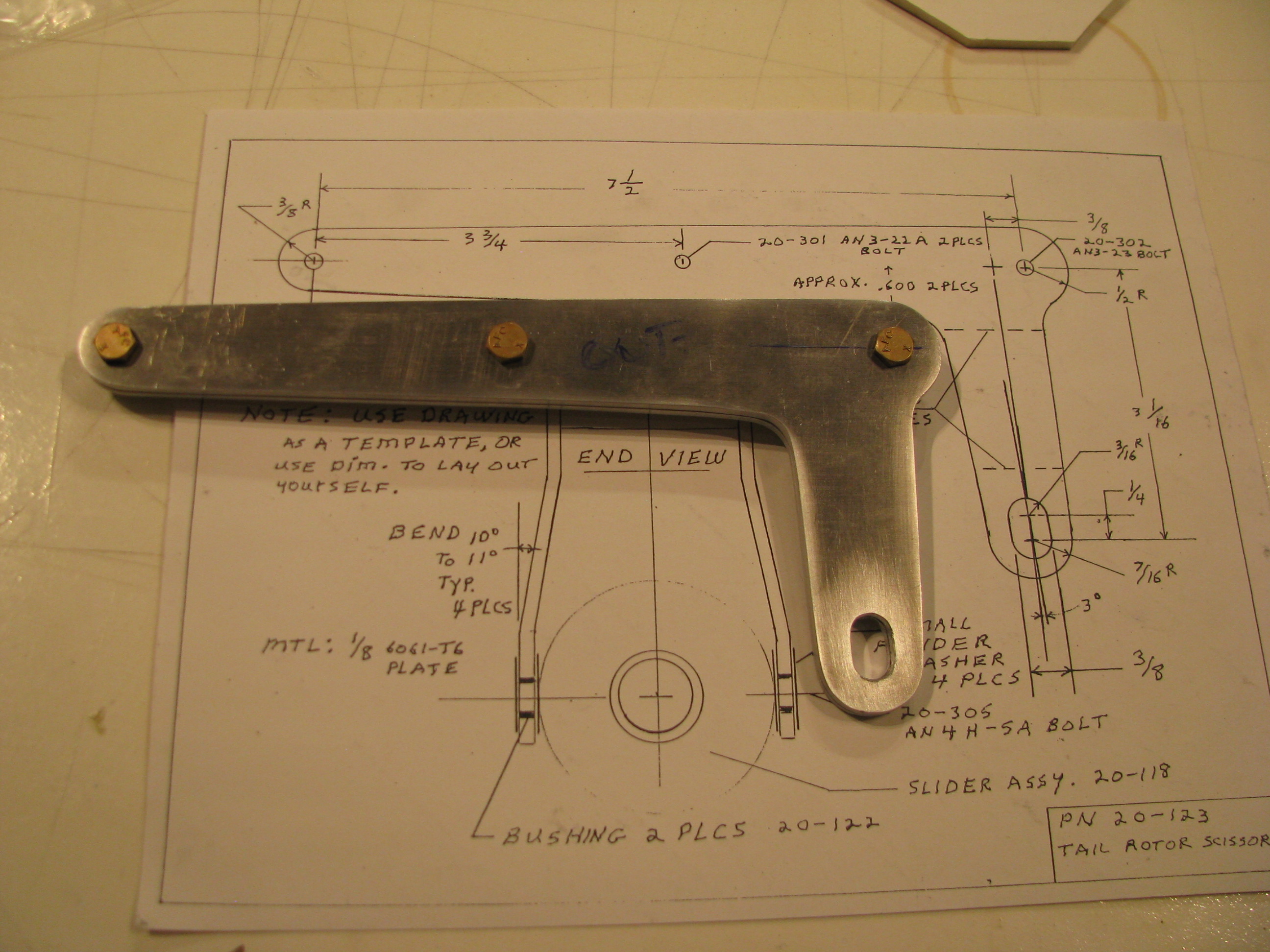
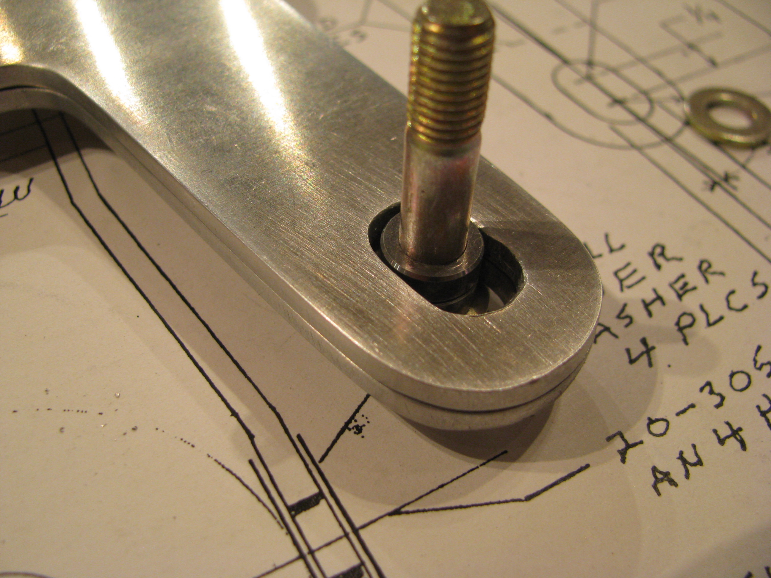
Doing it by hand is definitely not as precise. At one point in the slide there is a tiny bit of slop in the slot between the sleeved bolt and the aluminum. Probably 0.005” - Just enough to “tick” back and forth. I haven’t decided if this is enough to make me go back and fabricate new parts. I think I will see how much play there is when the whole thing is assembled. There are multiple bends and the slop may be “eaten” up by tolerances elsewhere. If there is any play when the tail rotor is installed I will re-fab the parts as I am guessing the tail rotor must be completely slop-free as it is subject to high frequency vibrations and much stress.
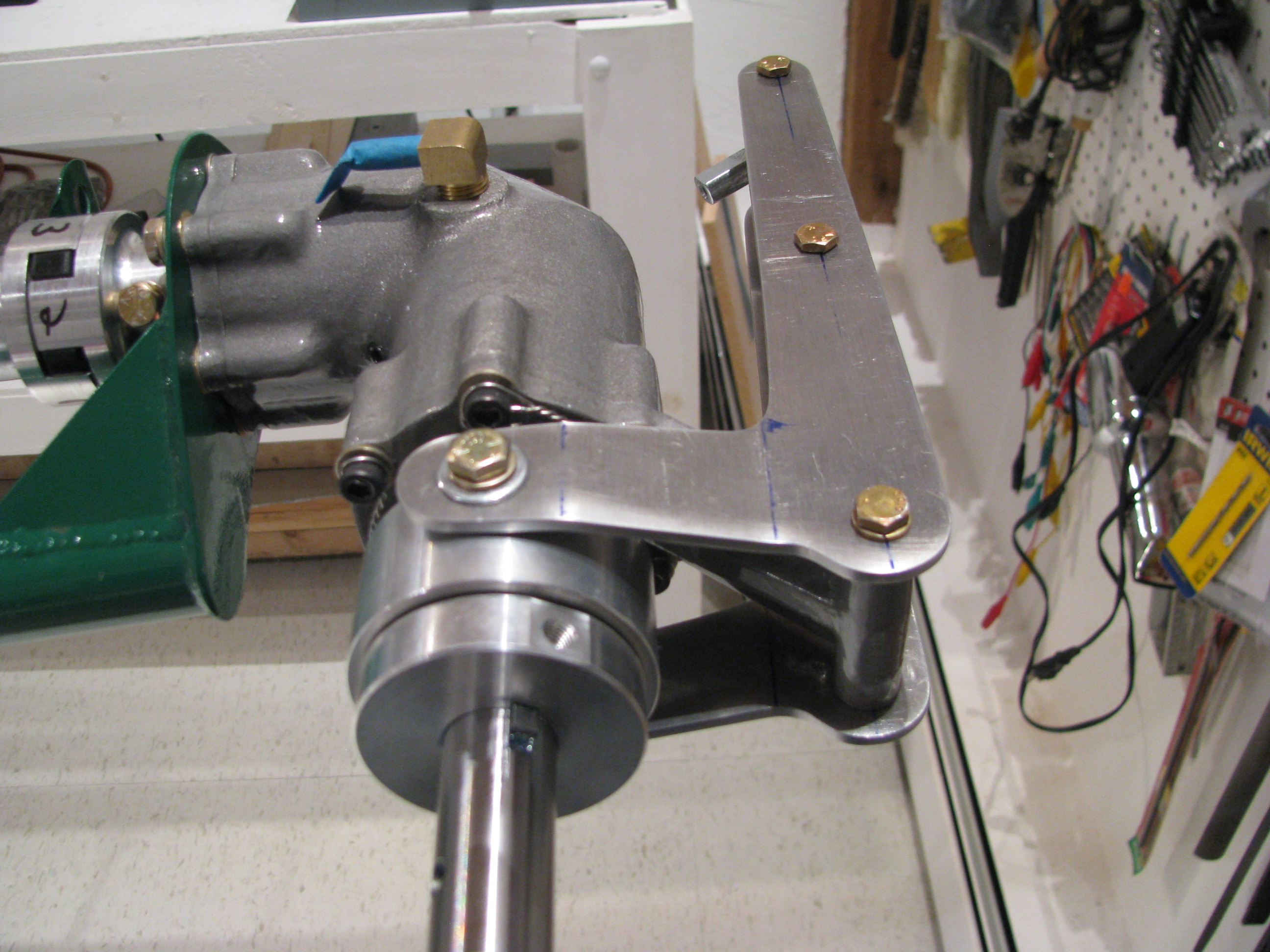
Bent and assembled the control arm scissors. Although it feels nice and snug, if you shwang the slider bearing back and forth you can feel a little play in the upper arm. I will fabricate new arms, but will use these for now for fitting and general assembly.