Turbine
Jack Table
12/07/14 22:23 Filed in: All
Well, I finally finished everything I could think of on the engine prior to the mounting.
The engine went on the floor and I modified the cradle so I could just hoist it straight up and out.
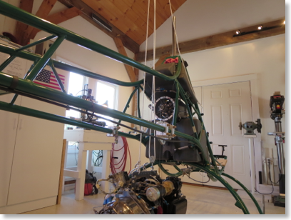
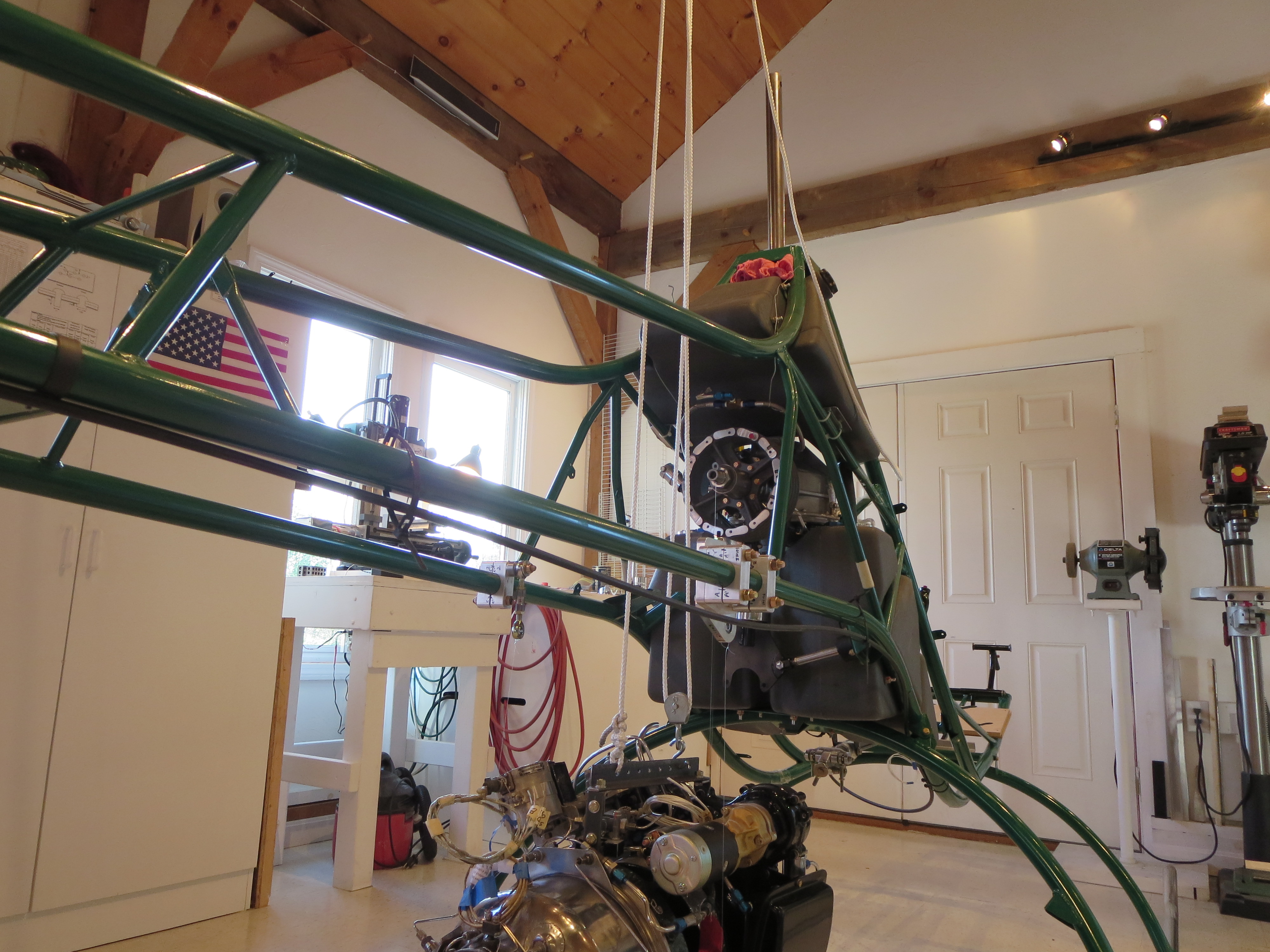
Then I tried lifting the engine with my pulley system. Two problems; 1) The rope was quite stretchy. I can't imagine trying to position the engine precisely with this system., and 2) Seeing the engine dangling from a few thin strands was too nerve-wracking. That's 10-15K worth of turbine swinging on some home-depot rope.
It probably would have been fine, but between the swinging and the tough precision thing I knew I wanted to do something different.
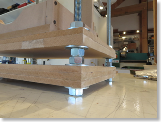
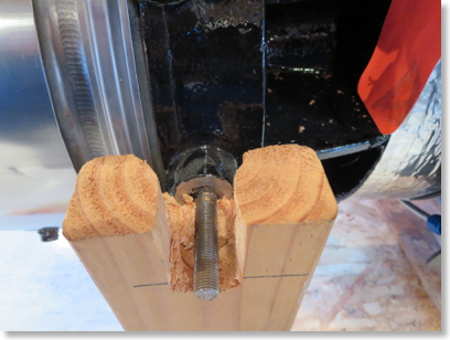
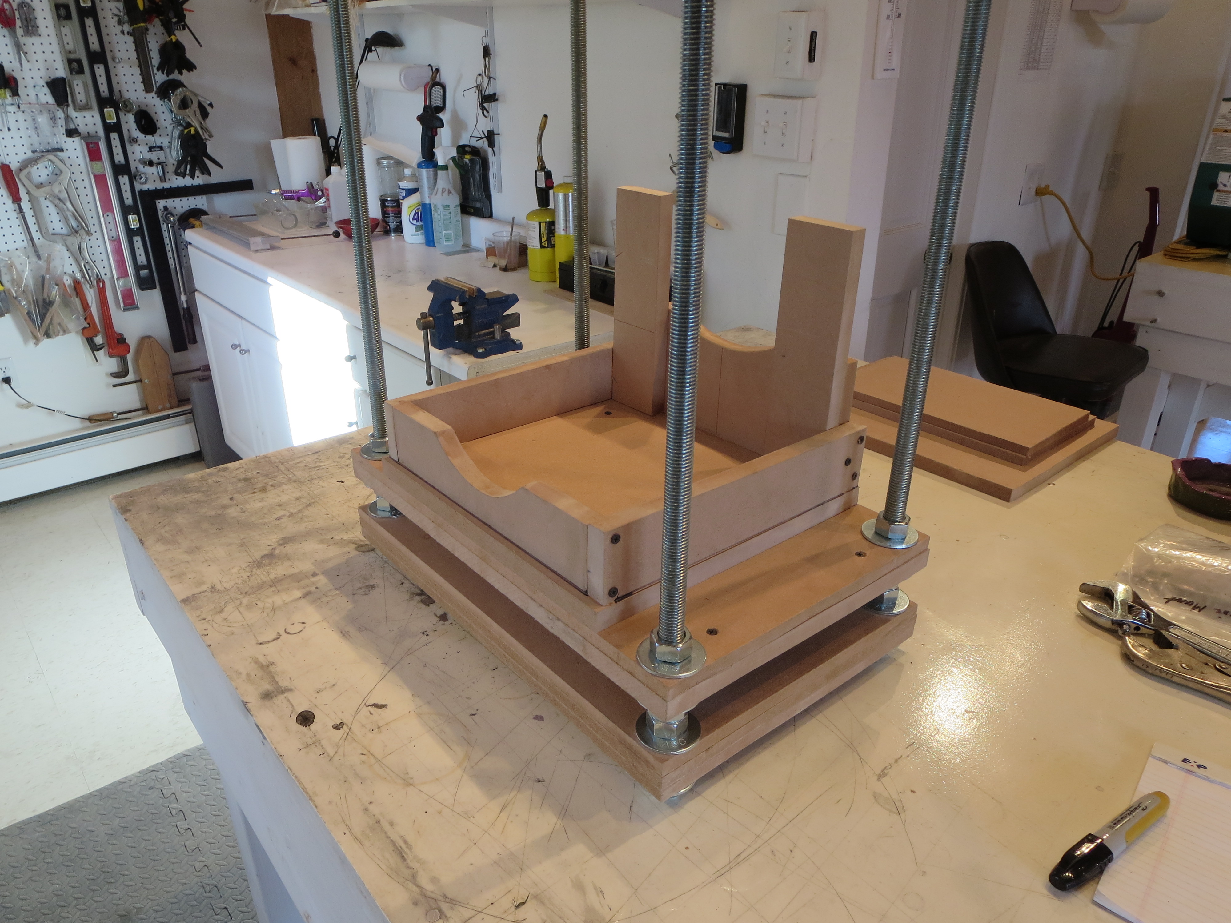
So I went to Home Depot and picked up some 3/4" threaded rod,washers, and nuts. 3/4" is certainly way overkill for the engine's weight, it's more for the stiffness so I don't need much more structure to keep the torsion and twist under control. I had a ton of MDF pieces left over from my CNC router project.
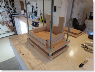
I made a new cradle for the turbine and added another thick interim layer to keep the whole thing stiff.
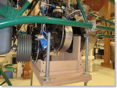
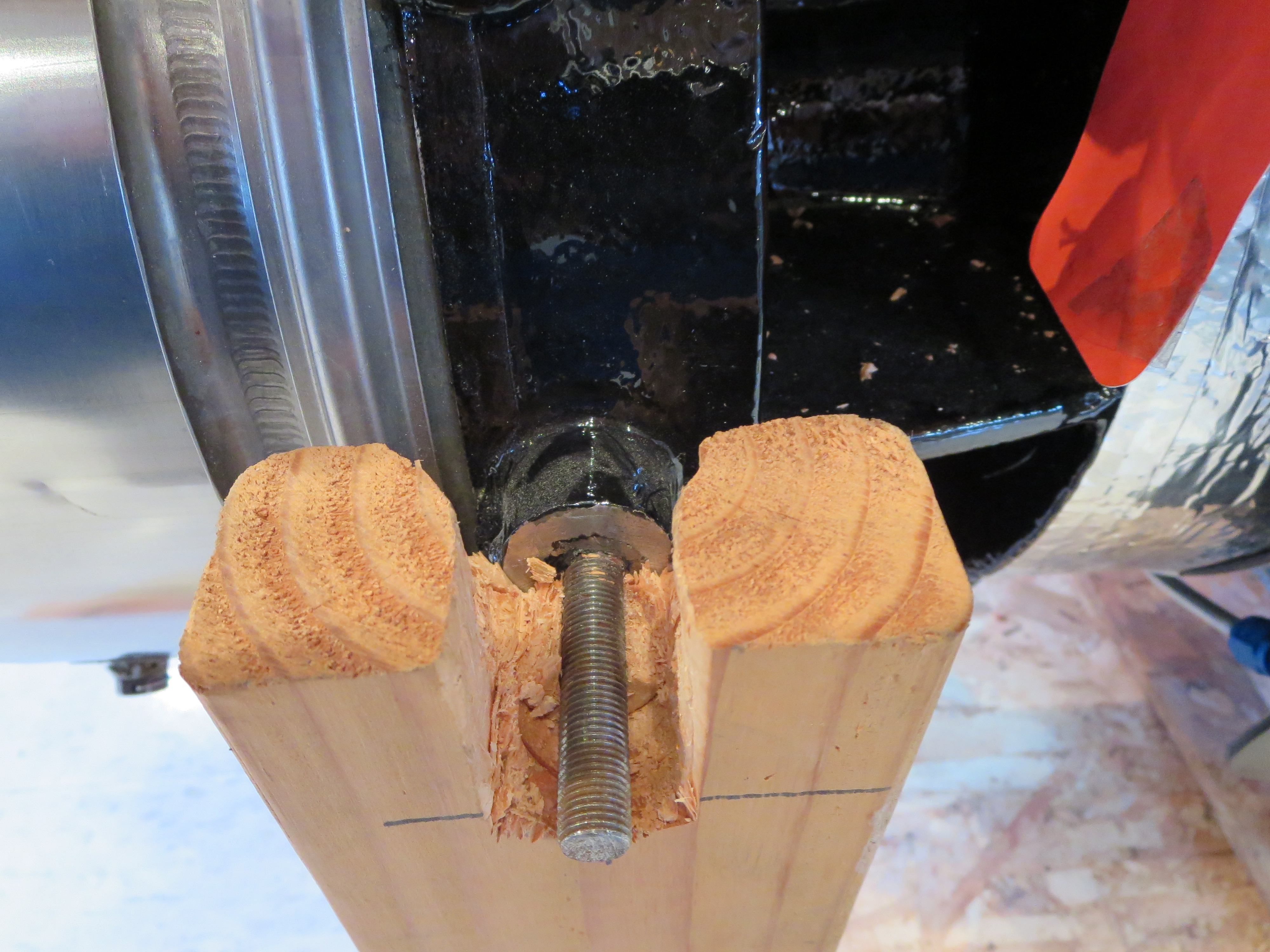
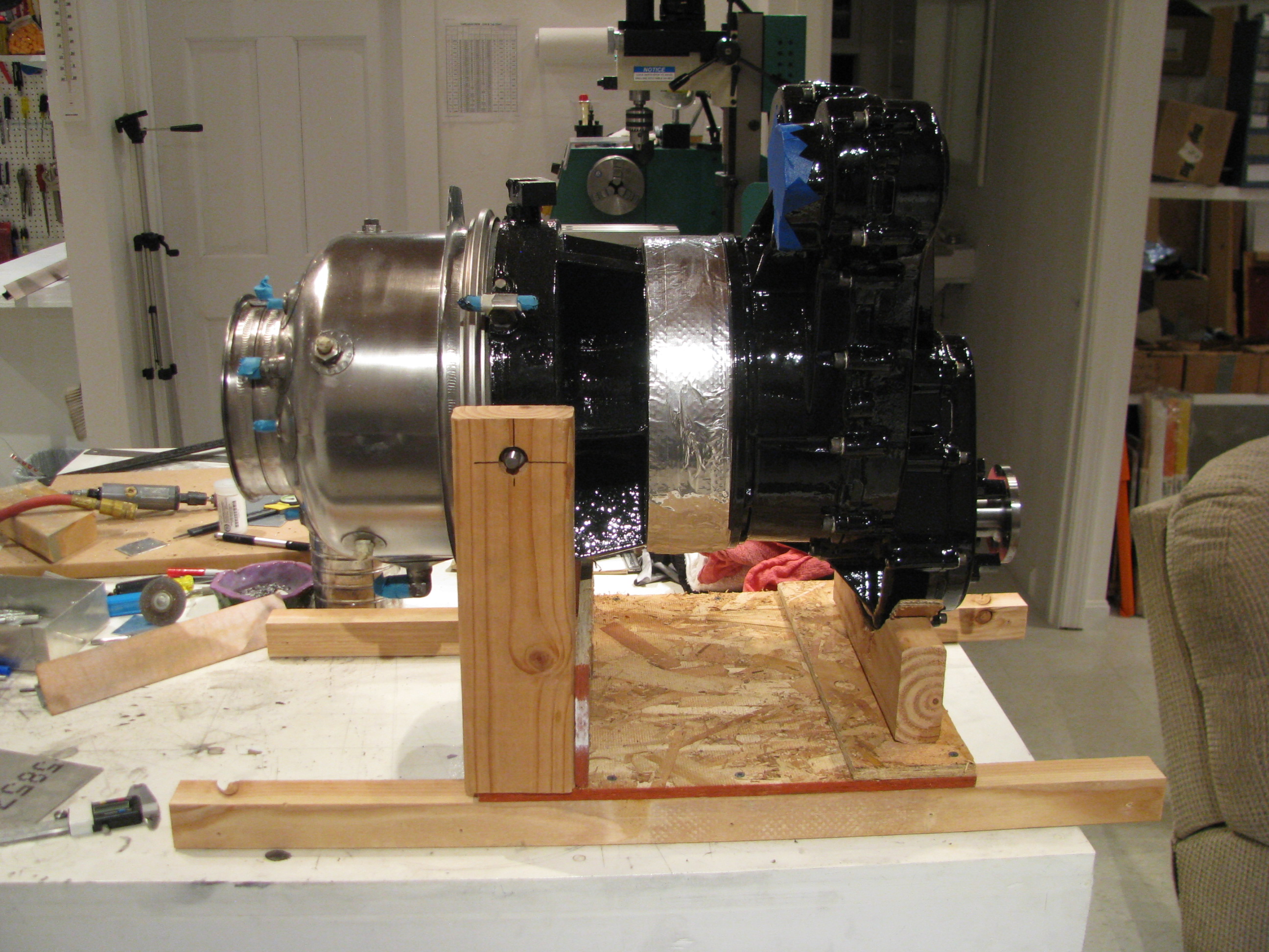
The idea is to transfer the turbine over to this jacking table and use the nuts to incrementally raise the engine up. Should be very safe and allow for very precise positioning.
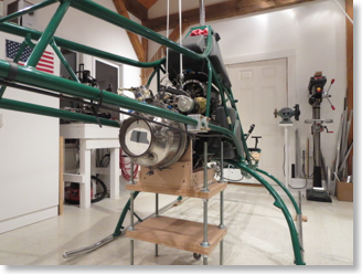
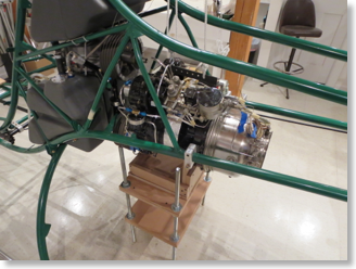
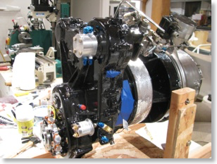
So here is the turbine in position after incrementally jacking it into position. It's very stable and certainly not going anywhere, so I can fiddle with alignment all I care to before locking it down permanently.
HERE is the whole process of building the table and jacking the turbine.
Of course after taking the photos and staring at it I realize I forgot to put the belts on so I will have to lower it a couple of inches and slide the belts on.
The engine went on the floor and I modified the cradle so I could just hoist it straight up and out.
Then I tried lifting the engine with my pulley system. Two problems; 1) The rope was quite stretchy. I can't imagine trying to position the engine precisely with this system., and 2) Seeing the engine dangling from a few thin strands was too nerve-wracking. That's 10-15K worth of turbine swinging on some home-depot rope.
It probably would have been fine, but between the swinging and the tough precision thing I knew I wanted to do something different.
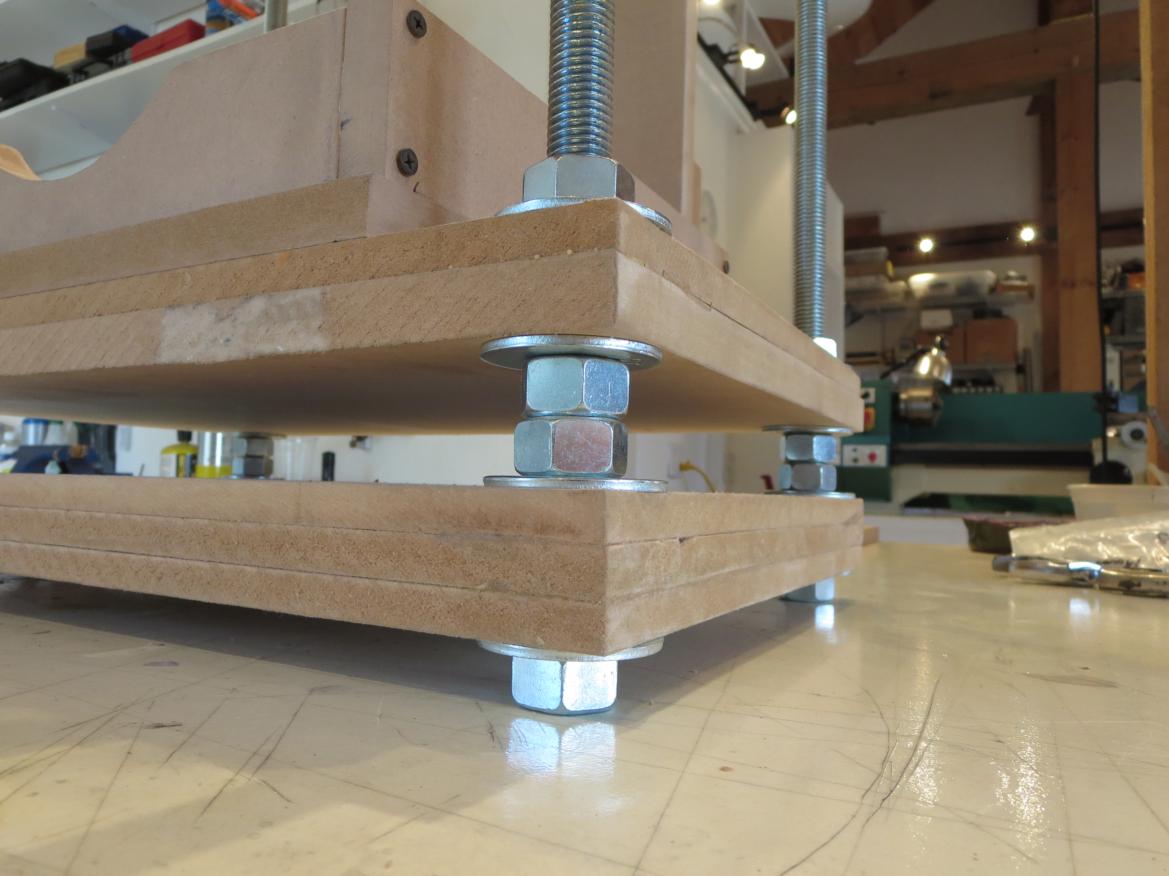
So I went to Home Depot and picked up some 3/4" threaded rod,washers, and nuts. 3/4" is certainly way overkill for the engine's weight, it's more for the stiffness so I don't need much more structure to keep the torsion and twist under control. I had a ton of MDF pieces left over from my CNC router project.
I made a new cradle for the turbine and added another thick interim layer to keep the whole thing stiff.
The idea is to transfer the turbine over to this jacking table and use the nuts to incrementally raise the engine up. Should be very safe and allow for very precise positioning.
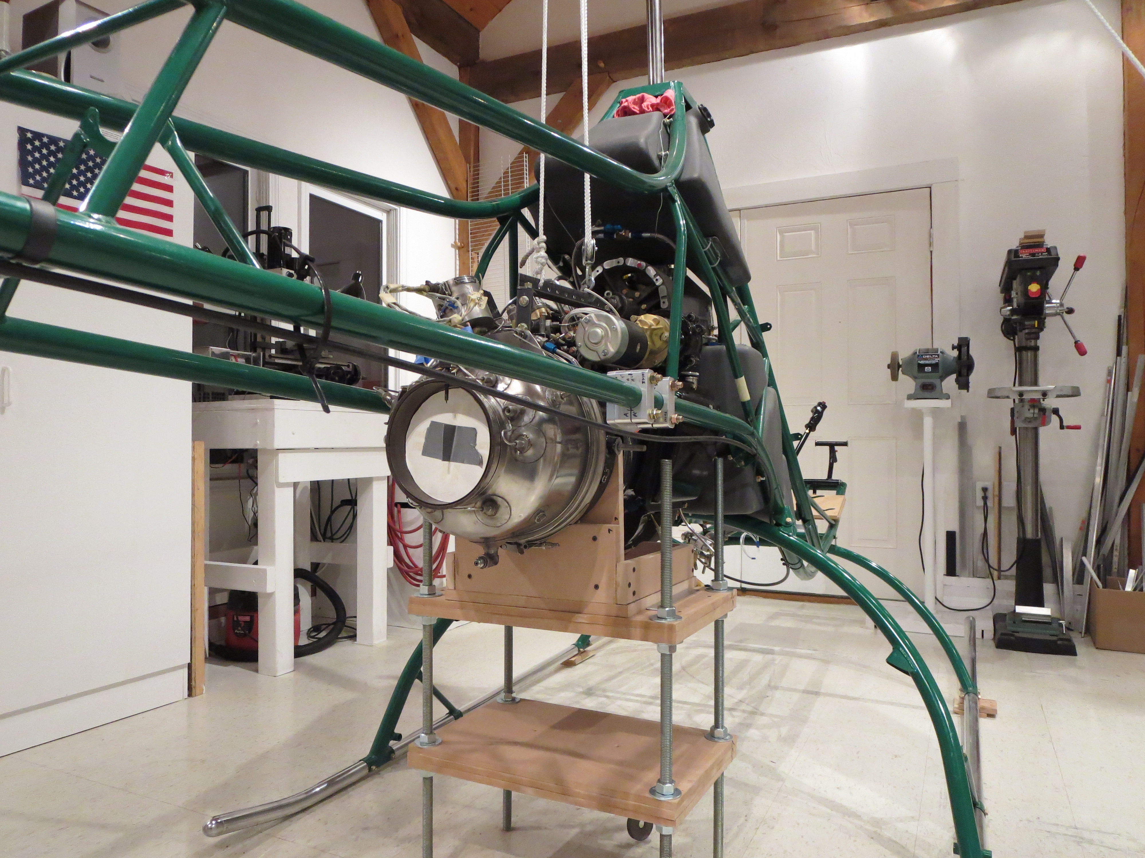
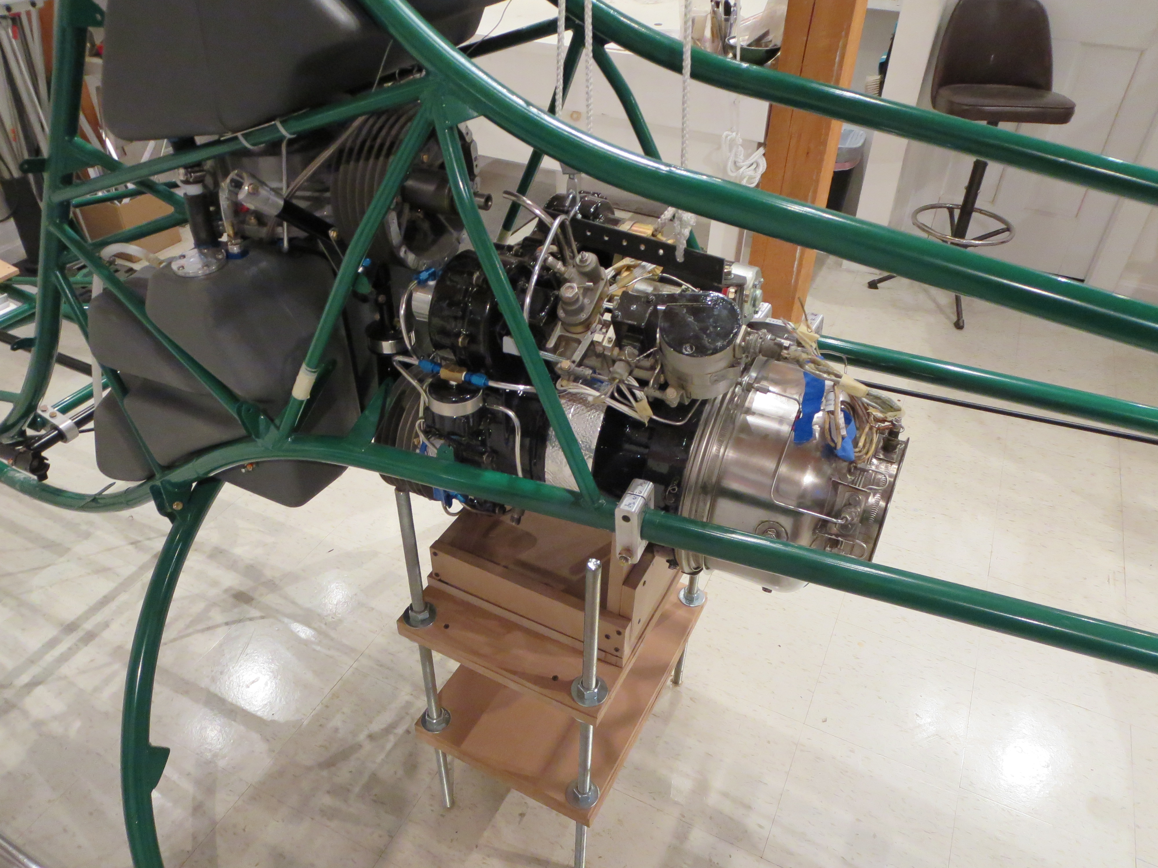
So here is the turbine in position after incrementally jacking it into position. It's very stable and certainly not going anywhere, so I can fiddle with alignment all I care to before locking it down permanently.
HERE is the whole process of building the table and jacking the turbine.
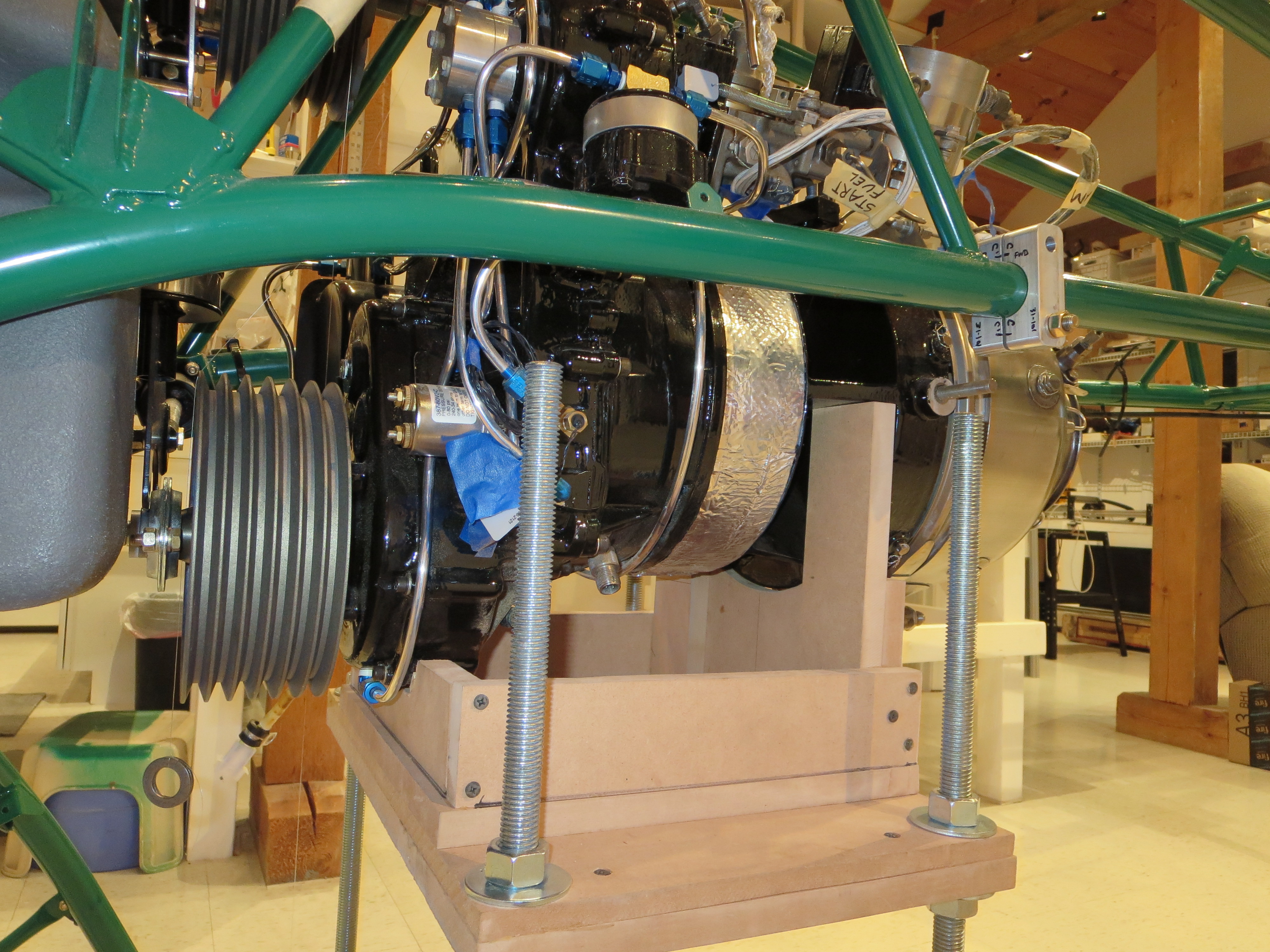
Of course after taking the photos and staring at it I realize I forgot to put the belts on so I will have to lower it a couple of inches and slide the belts on.
Engine Prep
12/01/14 21:49 Filed in: All
Here's another reason why I am taking so long on this project.
You have to fabricate a little bracket to attach the throttle return spring. I have seen Helicycles that just use a piece of angle here. Well, I shaped and sculpted that stupid little piece way more than necessary.
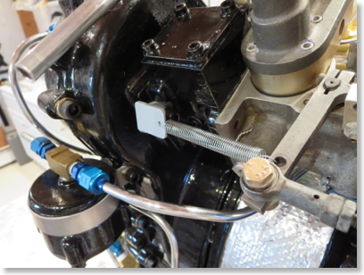 Here it is painted (well, primed, anyway) and mounted on the ship. Kind of a nothing of a task, but probably way easier on the bench than in the ship.
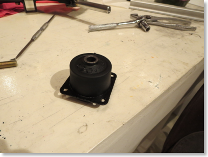
To prep the rubber clutch mount I coated it with Vaseline to loosen the mold-release skin, then rubbed it off the rubber, painted the metal plate (with diluted black nail polish for quick drying), then coated and soaked the rubber in Armor-All to keep the rubber "supple", and lastly coated the bore of the bushing with Corrosion-X. Again, probably overkill since I am sure many just bolt the darn thing in the ship without bothering with any of that.
If you take a half-full bottle of nail polish, top it off with acetone, and shake it up really well, you get a quick-n-dirty lacquer paint. It dries hard as soon as the acetone flashes off. It is not rugged, nor pretty, but for a quick corrosion inhibitor, it saves a ton of time versus real painting.
You have to fabricate a little bracket to attach the throttle return spring. I have seen Helicycles that just use a piece of angle here. Well, I shaped and sculpted that stupid little piece way more than necessary.
To prep the rubber clutch mount I coated it with Vaseline to loosen the mold-release skin, then rubbed it off the rubber, painted the metal plate (with diluted black nail polish for quick drying), then coated and soaked the rubber in Armor-All to keep the rubber "supple", and lastly coated the bore of the bushing with Corrosion-X. Again, probably overkill since I am sure many just bolt the darn thing in the ship without bothering with any of that.
If you take a half-full bottle of nail polish, top it off with acetone, and shake it up really well, you get a quick-n-dirty lacquer paint. It dries hard as soon as the acetone flashes off. It is not rugged, nor pretty, but for a quick corrosion inhibitor, it saves a ton of time versus real painting.
Engine Hoist Bracket
11/29/14 23:41 Filed in: All
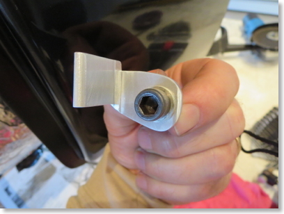
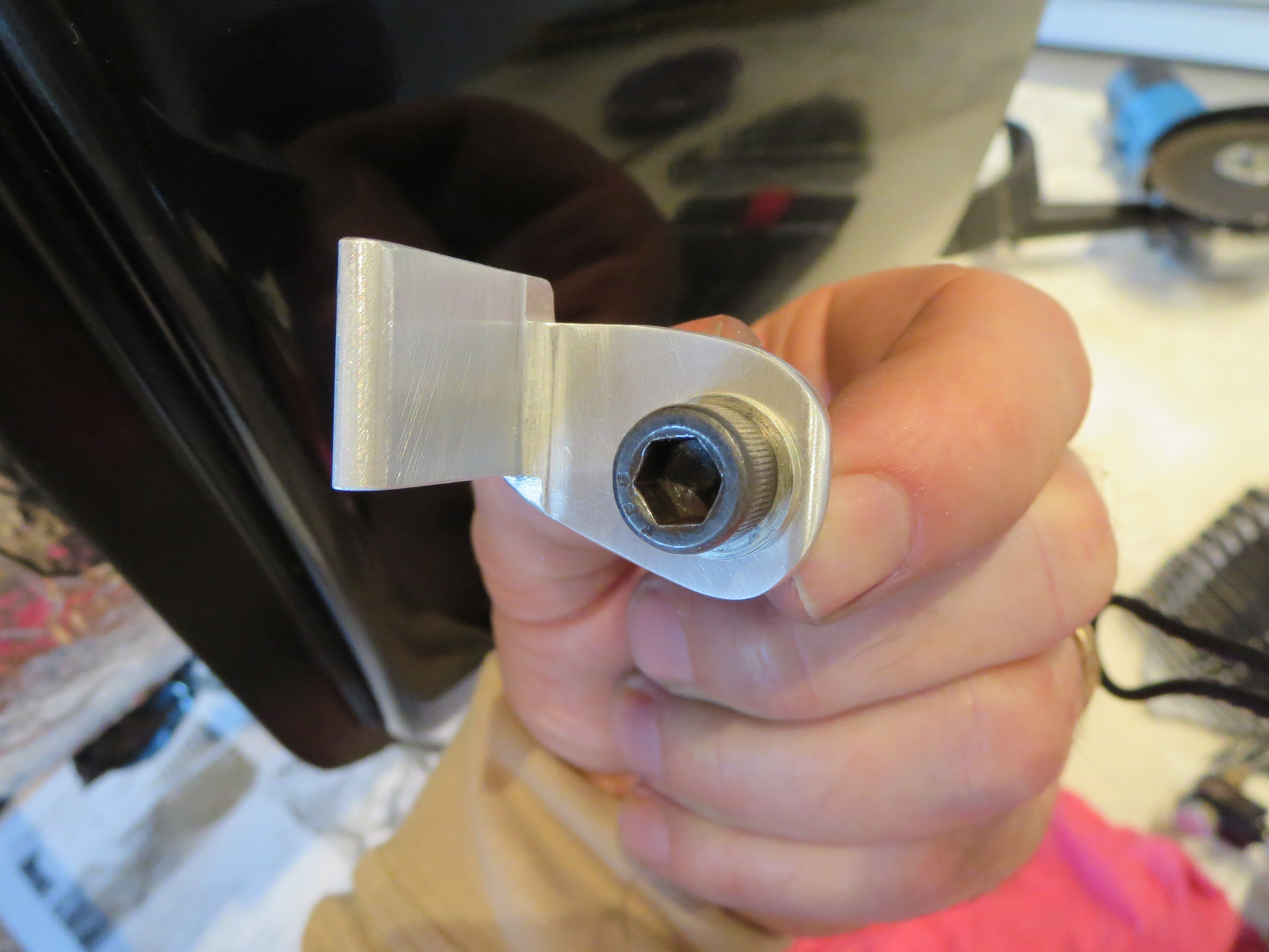
Made an engine hoist point to mount to turbine in prep for lifting it into position. I didn't like B.J.'s "wrap a chain around it" method in the videos, especially since I will likely be doing most of this solo.
That's just some hardware store GR8 bolts and angle iron from Home Depot. I had forgotten just how nice steel is to work with. Drilled a bunch of holes since I do not know where the CG of the engine is. This way I can just hook on the closest balance point. If this were a permanent thing I would have used more and better mounting points, but it is a single-use, single-function item.

That's just some hardware store GR8 bolts and angle iron from Home Depot. I had forgotten just how nice steel is to work with. Drilled a bunch of holes since I do not know where the CG of the engine is. This way I can just hook on the closest balance point. If this were a permanent thing I would have used more and better mounting points, but it is a single-use, single-function item.
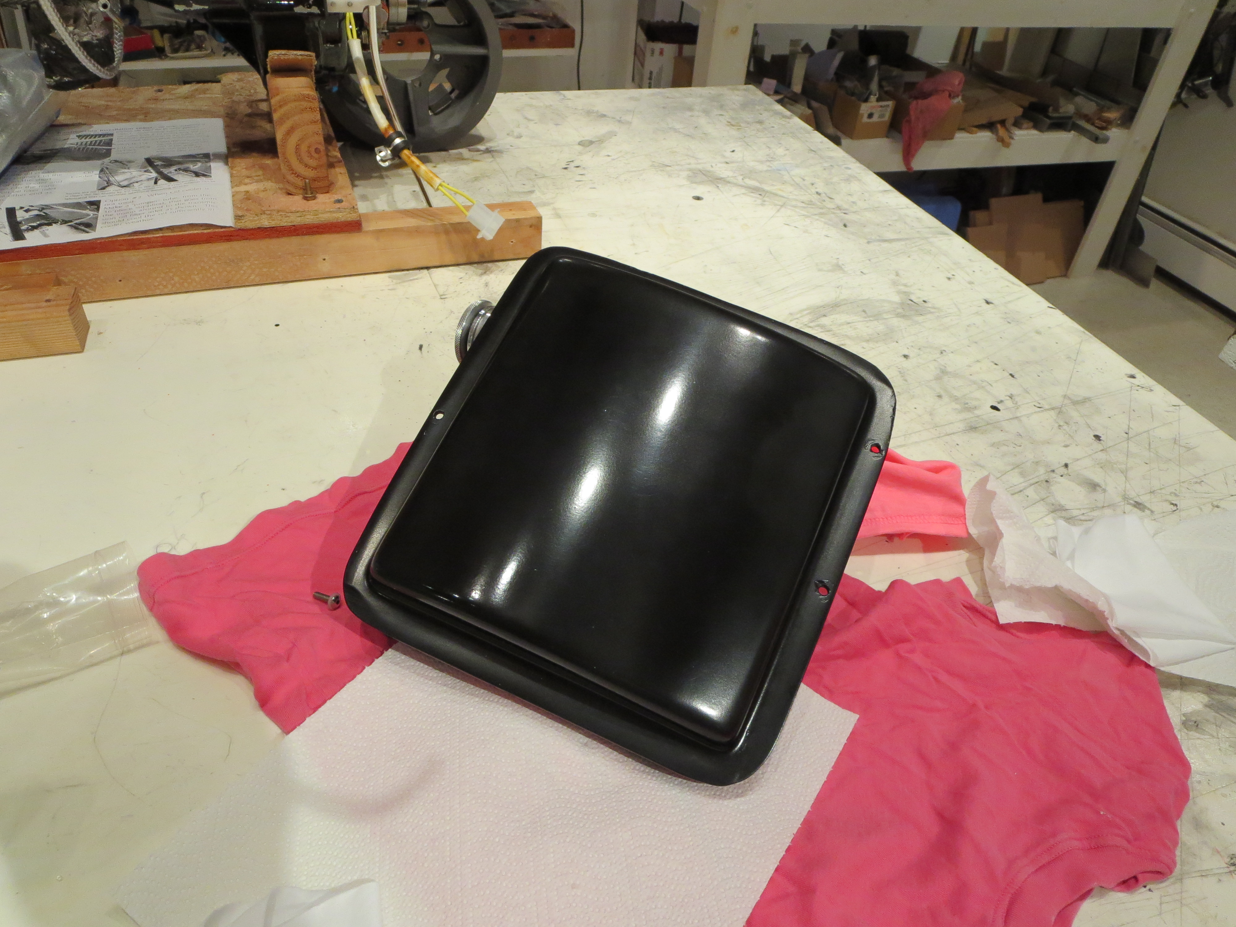
Oil Tank Buff
11/23/14 23:31 Filed in: All
Did a quick polish with 2 grades of Nuvite to smooth the oil tank paint a bit. I don't have any rubbing compound, but I have several grades of Nuvite that worked pretty well. Finished with a couple coats of McGuire's Wash Wax. Far from perfect, but not bad for cheap auto parts store "Epoxy Paint". I am still not sure how a single part rattle can paint can be "epoxy".
Engine Mount Prep
11/15/14 23:47 Filed in: All
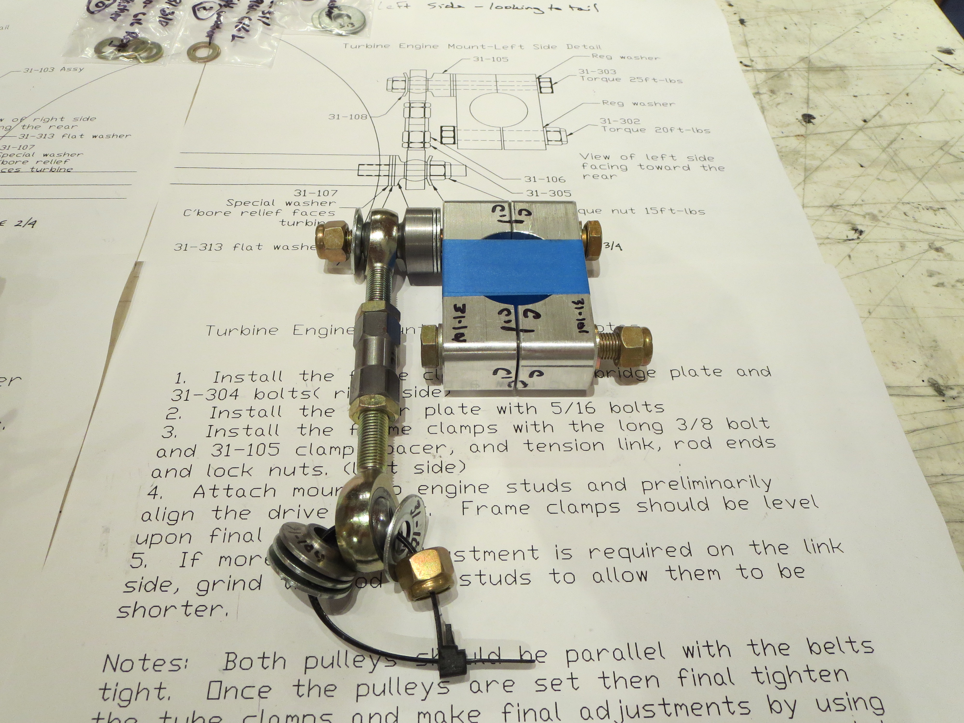
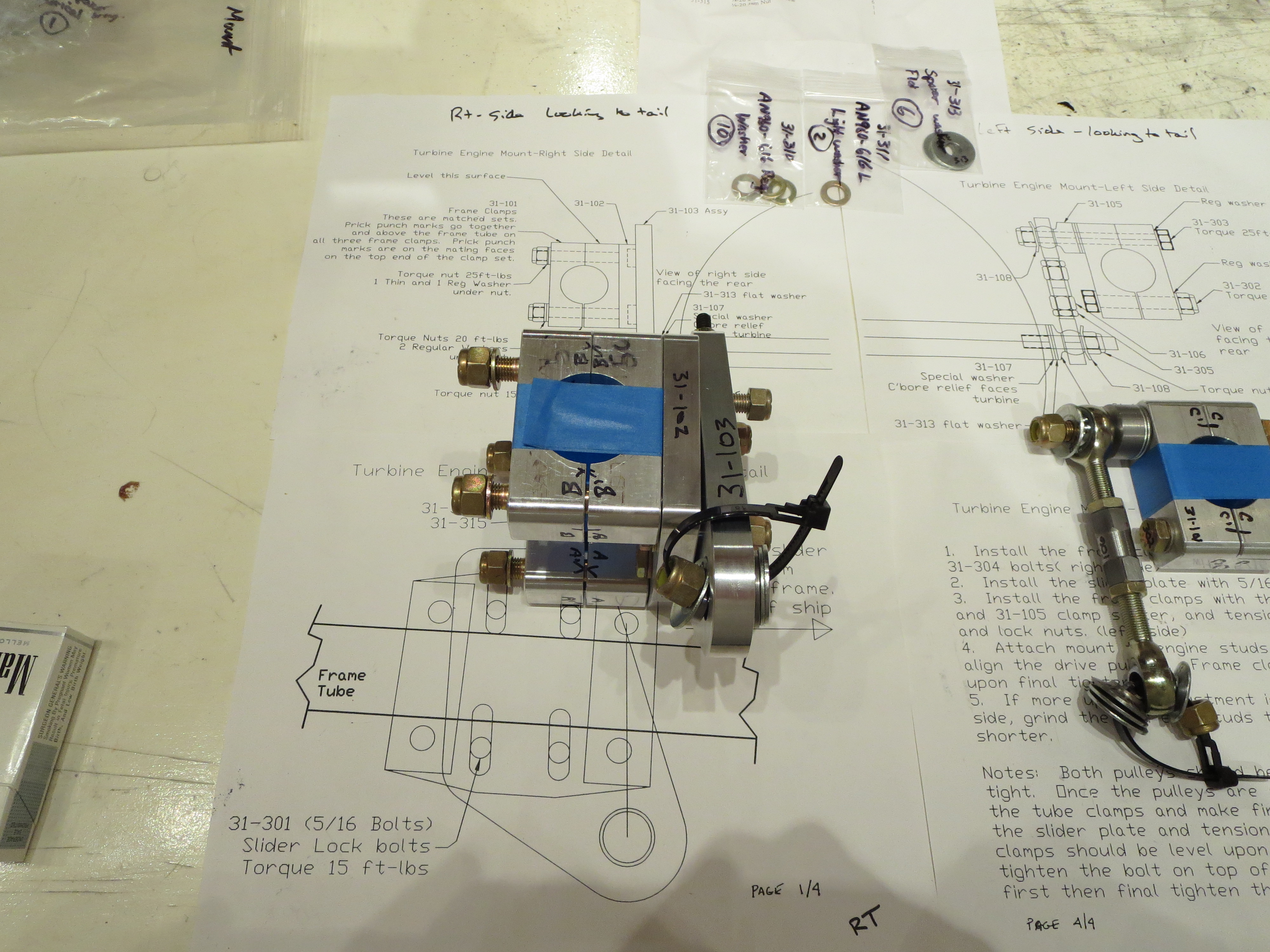
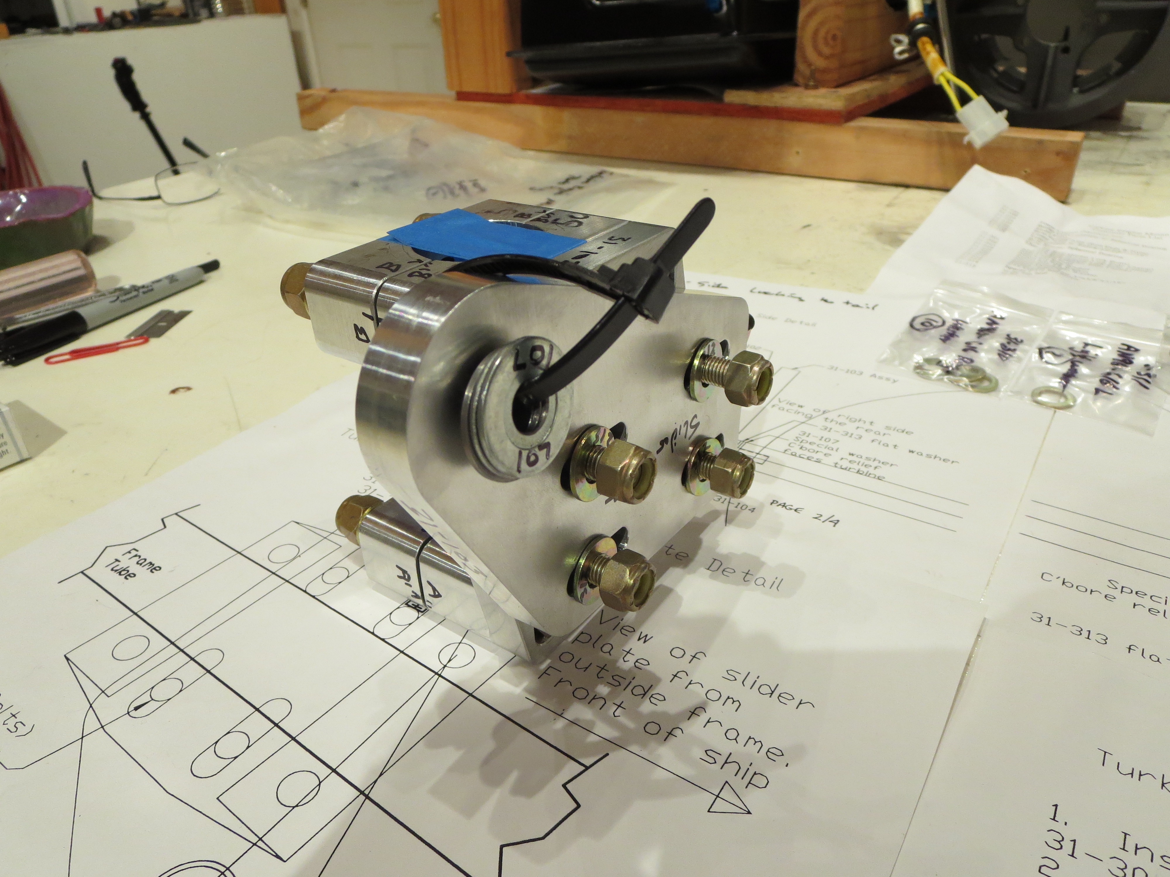
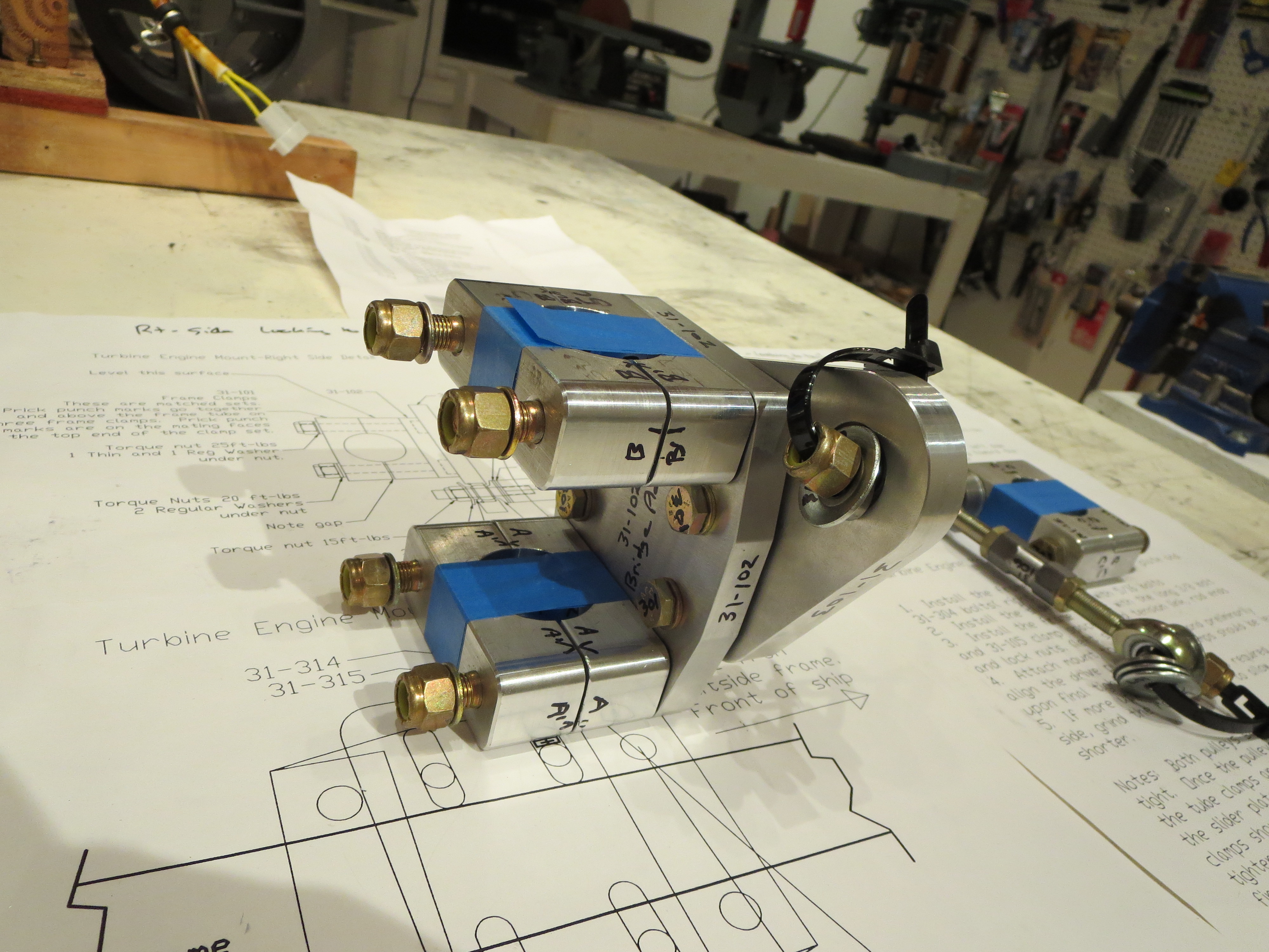
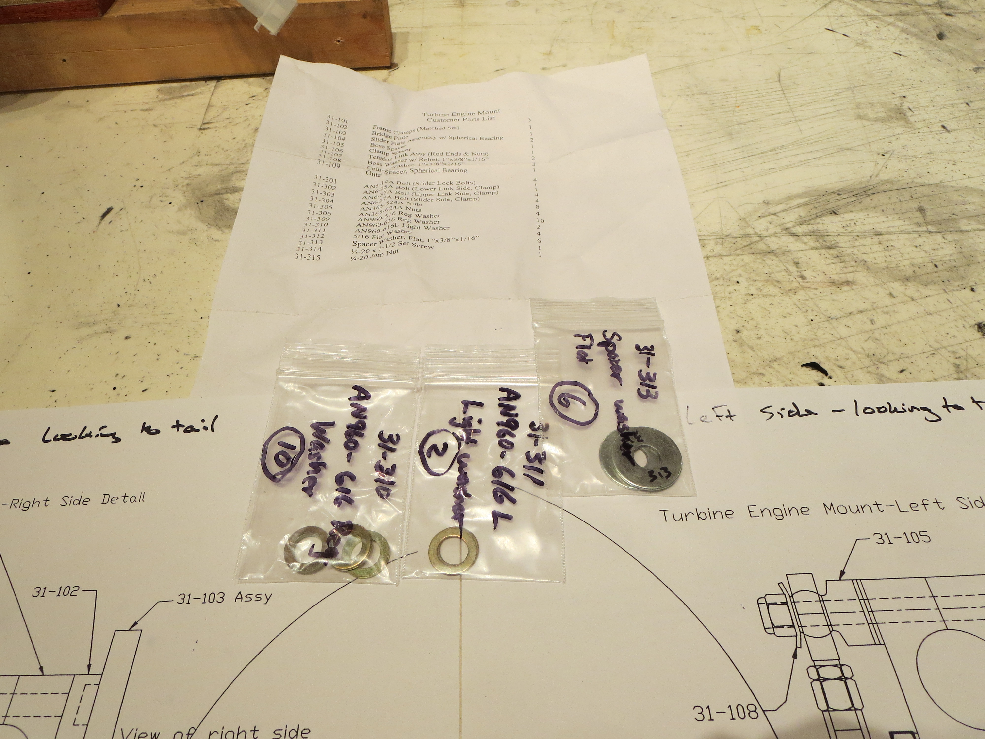
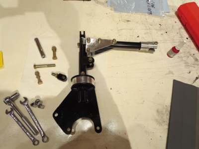
Getting ready to mount the engine. I inventoried and labeled all the engine mount parts and trial fitted the assemblies together. It may seem like overkill to label things like washers, but since I have no idea how often or when I get back to building sessions, I can't count on memory alone.
Here are the assemblies for left and right fit together.
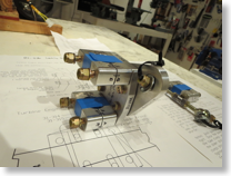
I have a question for Blake as to which way to install the bolts for the inner slider plate on the left side mount; nuts in or nuts out.
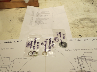
There are a few spare parts, all washers. I am assuming those are for proper spacing once the unit is installed in the ship.

I mounted a couple of heavy steel angles and pulleys to a large beam in my shop for winching the engine up into position.
Next up is to check the gear (since major weight will be on it now), and complete the wiring of the engine, then the mounting starts.
Here are the assemblies for left and right fit together.
I have a question for Blake as to which way to install the bolts for the inner slider plate on the left side mount; nuts in or nuts out.
There are a few spare parts, all washers. I am assuming those are for proper spacing once the unit is installed in the ship.
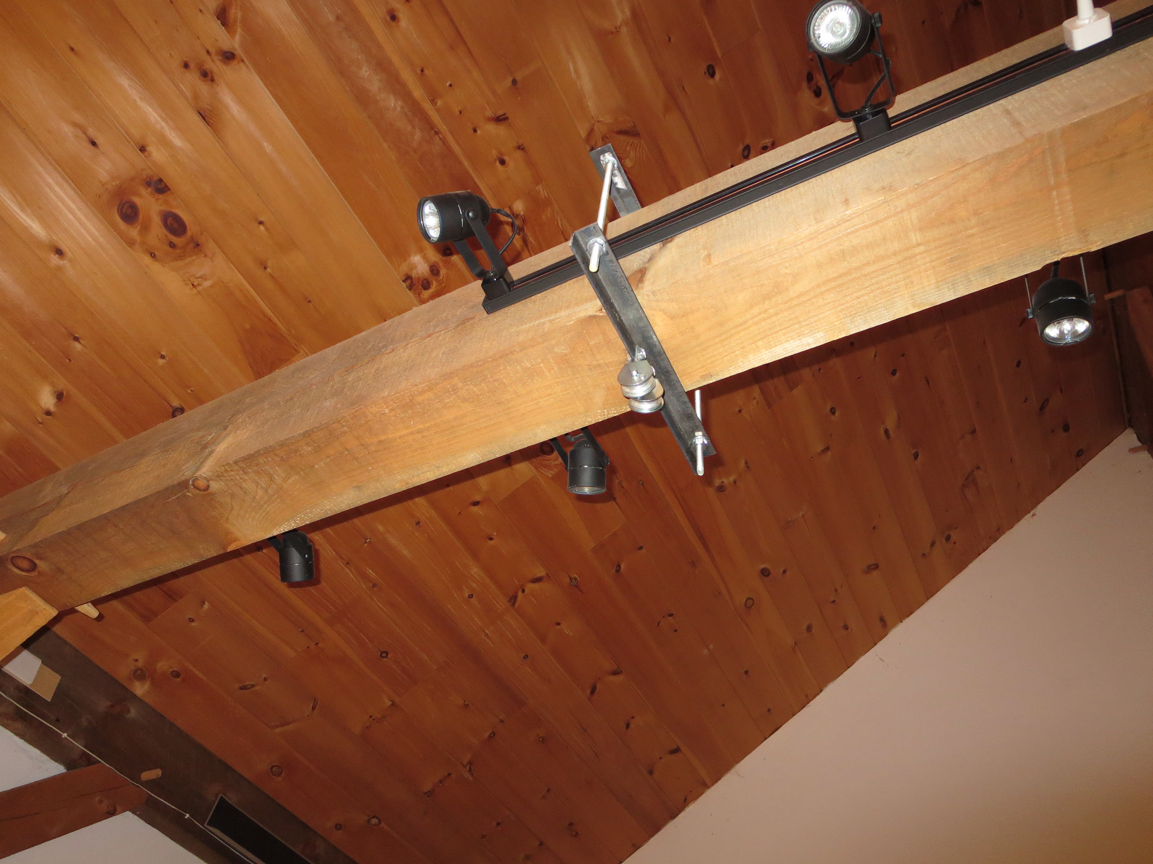
I mounted a couple of heavy steel angles and pulleys to a large beam in my shop for winching the engine up into position.
Next up is to check the gear (since major weight will be on it now), and complete the wiring of the engine, then the mounting starts.
Clutch Final Assembled
03/03/14 00:38 Filed in: All
Painted and final assembled the clutch.
I used the Hap Miller compression disk instead of the stock rubber biscuit. Looks nicer and should be more stable. The bolts holding the angle plates are only bolted through the tubes, so the bolts can't really be torqued to spec (60 in-lb) without deforming the tubes, so torque was lowered a bit. All bolts were Loctited and all sliding surfaces were greased prior to final assembly.

I used the Hap Miller compression disk instead of the stock rubber biscuit. Looks nicer and should be more stable. The bolts holding the angle plates are only bolted through the tubes, so the bolts can't really be torqued to spec (60 in-lb) without deforming the tubes, so torque was lowered a bit. All bolts were Loctited and all sliding surfaces were greased prior to final assembly.
Mixer Assembled
02/28/14 00:14 Filed in: All
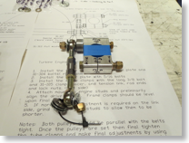
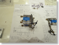
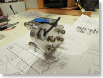
Finished up assembly of the mixer.
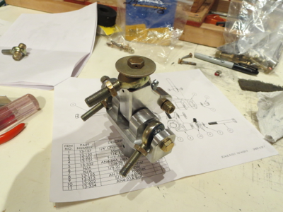
This is so much nicer than the original item. It looks and feels like a quality item.

This is so much nicer than the original item. It looks and feels like a quality item.
Clutch Pre-Assembly
02/17/14 23:58 Filed in: All
The clutch is pretty basic. First, install a threaded steel plug in the top piece and cross drill for a bolt. I don't have picture, but found a little trick. BJ says to use a vice or a press to jam in the plug. I looked down the tube and plug with a small flashlight shining UP through the tube. It could be seen that the steel tube was slightly out of round (probably from the welding). Well, just give a light squeeze in a vice to the tube on the wide sides and the plug just tap, taps in with a little piece of wood - actually very gently. No ham-handed vice-pressing needed.
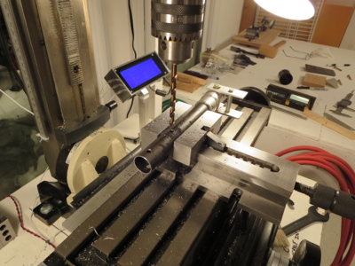
Next up is drilling the side plates to the clutch lever arm. I made use of my jig plates (from the cyclic tube mixer mount operation) to get a perfect alignment between the bolts and the holes for the plates.
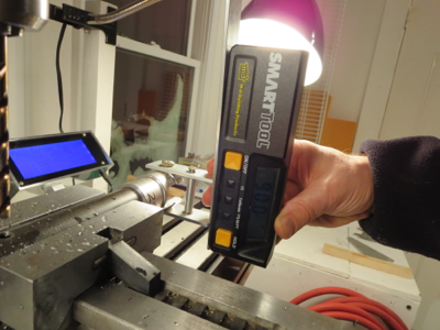
Jig plates repurposed and alignment exact. It pays to make sure that mill is perfectly level and mill head is trammed. Then everything can be referenced to 0.0 degrees or 90.0 degrees.
It seems like a pain to make little jig thingies for a single operation, but I usually can find a secondary purpose for them which make the time spent much more worthwhile.
Complete clutch assembly pre-fitted (except rubber parts and bearing). Now I just have to tidy up the steel parts (they picked up some scale having sat for so long), prime, and paint. With the precision of the mill, and no broken drill bits, the pieces just fall together, snug and true. The clutch is a very simple assembly project.

Next up is drilling the side plates to the clutch lever arm. I made use of my jig plates (from the cyclic tube mixer mount operation) to get a perfect alignment between the bolts and the holes for the plates.

Jig plates repurposed and alignment exact. It pays to make sure that mill is perfectly level and mill head is trammed. Then everything can be referenced to 0.0 degrees or 90.0 degrees.
It seems like a pain to make little jig thingies for a single operation, but I usually can find a secondary purpose for them which make the time spent much more worthwhile.

Complete clutch assembly pre-fitted (except rubber parts and bearing). Now I just have to tidy up the steel parts (they picked up some scale having sat for so long), prime, and paint. With the precision of the mill, and no broken drill bits, the pieces just fall together, snug and true. The clutch is a very simple assembly project.
Turbine Plumbing Done
05/27/13 14:29 Filed in: All
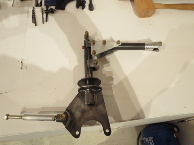
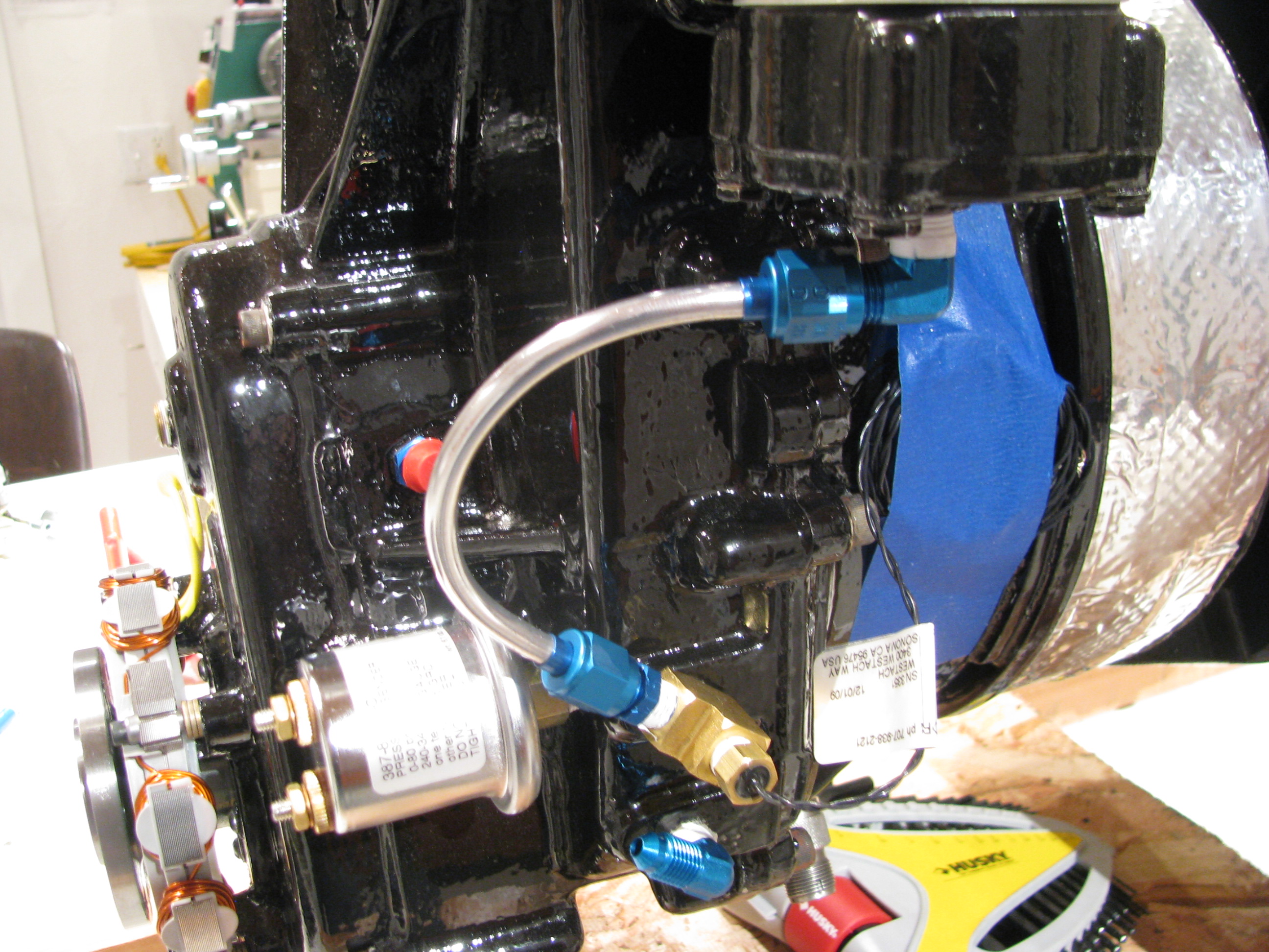
Completed plumbing of the engine oil system.
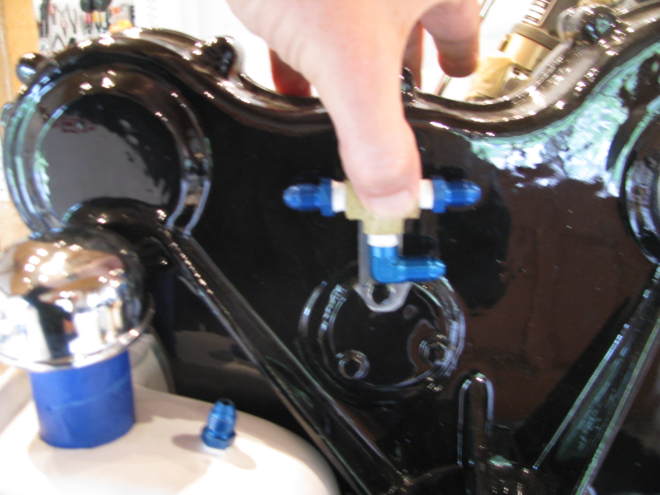
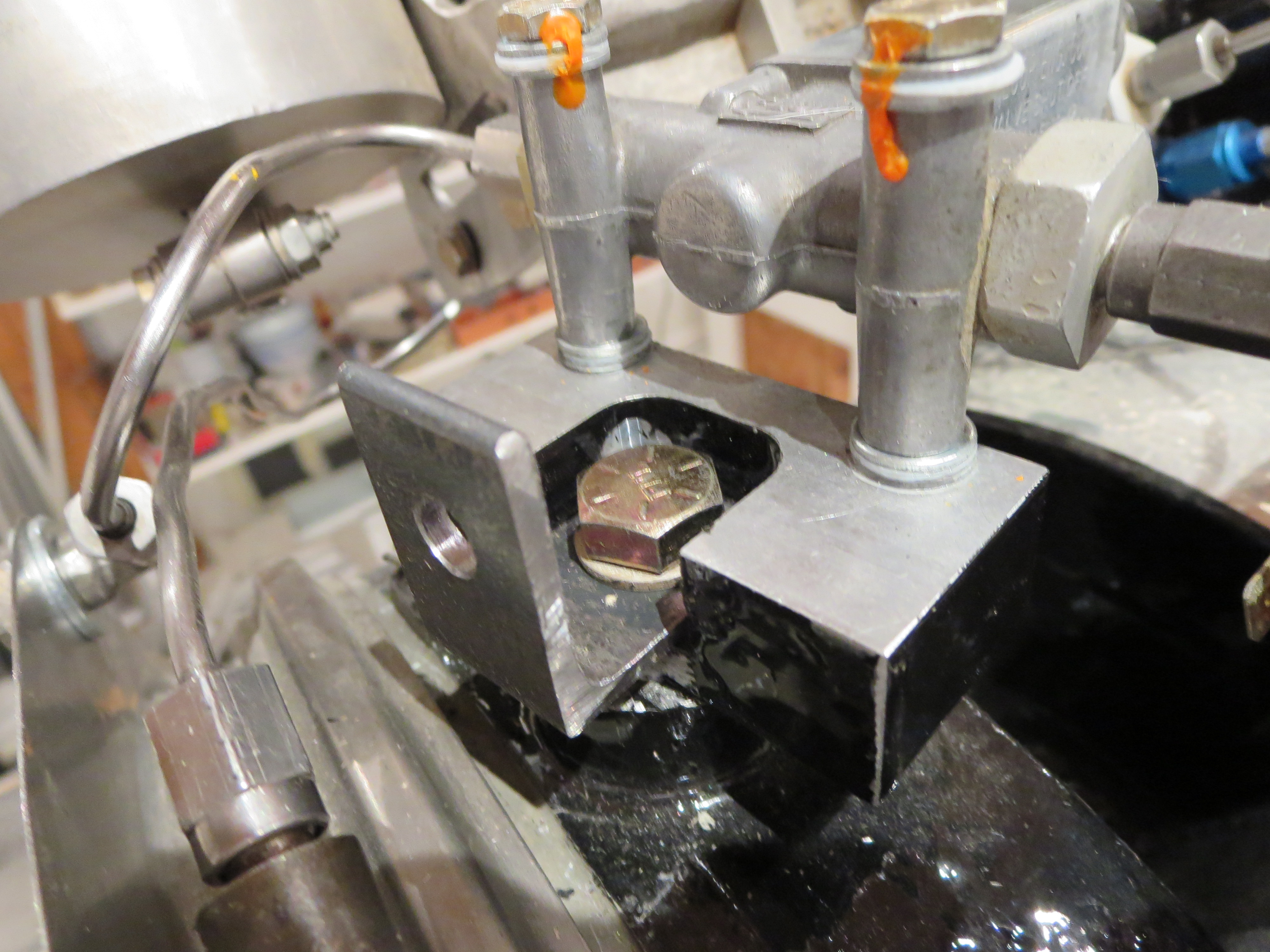
My tubing flare tool clamps just about an inch of tube, so you can’t begin a bend until then. I found it easier to offset the central Tee about an inch to be able to make the line from the top of the tank possible.
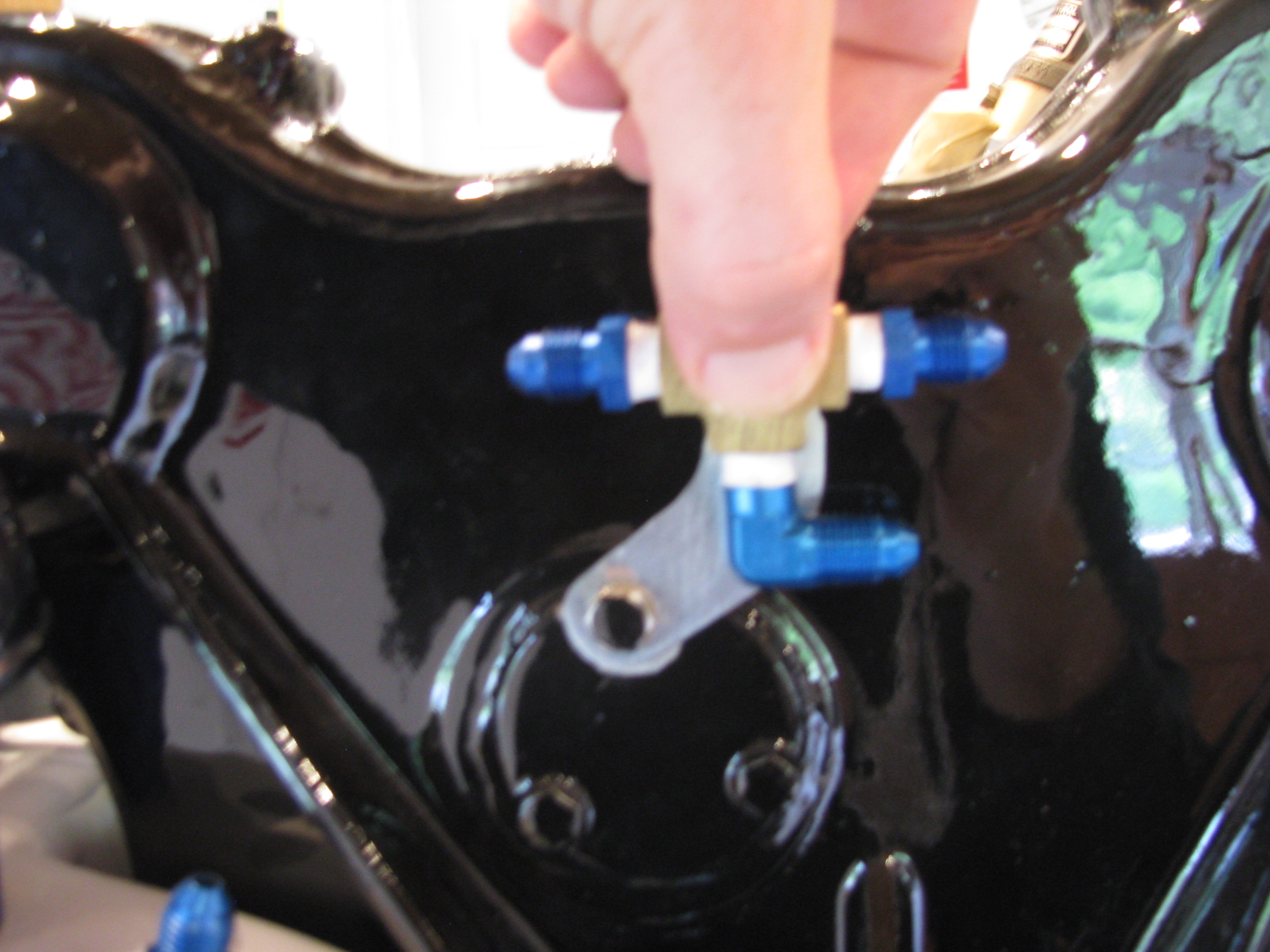
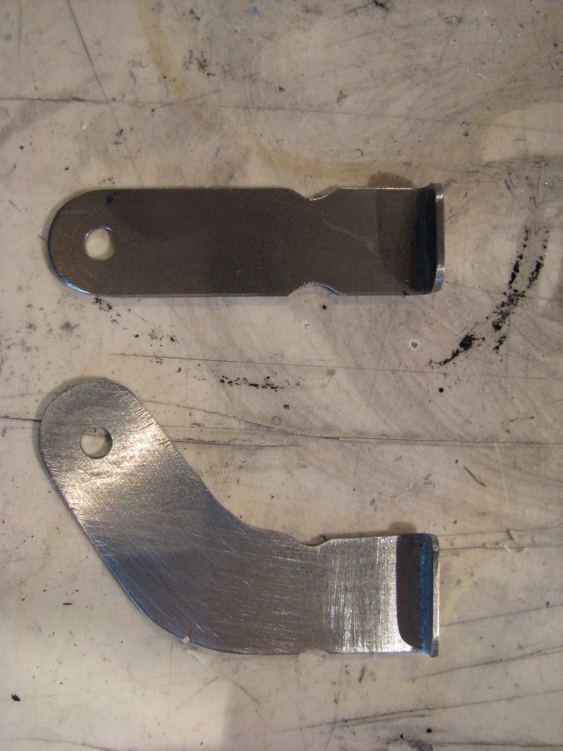
The top bracket is per BJ’s instructions. The lower one is bent for the actual offset needed so the bends were not too tight.
The money shot. Doing the tubing is a pleasant project. Try the run with wire first for test fitting, cut the tube, gently coax it into shape, polish, flare (don’t forget to add the fittings first - done that), and it all comes together. My son’s girlfriend said it looks like some 50’s science fiction movie prop with all the gadgets and tubes.
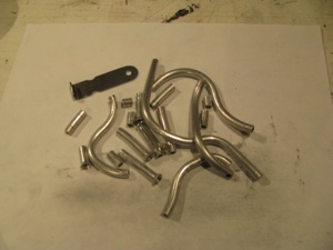
I don’t know if anyone else has the problems of a lot of scrap. This being a trial and error kind of thing I ended up with a lot of little pieces like this. I had to actually buy more Versatube from A.S.&S. to finish my job.
I got enough to make BJ’s “poor man’s oil cooler” should it be needed. I will try without first as I am in a chillier climate (especially this year). I’m not a fan of blocking the inlet airflow.
Oil Tank Fab
05/10/13 14:24 Filed in: All
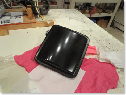
Completed Oil Tank and mounting hardware (finally).
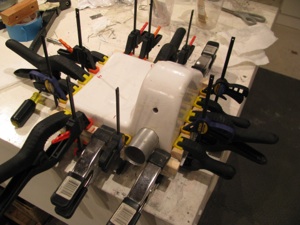
Fiberglassing together tank halves. Tidy up the insides (some stray bits of glass and cloth needed trimming, clean the surfaces with acetone, and bond the sides with a thick mixture of flox and resin.
Check for extrusion out each edge and clamp the hell out of it.
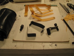
The tank mount brackets. You can see my many trial cardboard templates.
Thankfully I had an old ZVBox case that was 0.048” steel which I could use as a donor since there really isn’t enough steel strapping supplied to make the brackets, especially in the weird shapes you actually need, as opposed to the nice straight ones that BJ shows.

The videos show only two mounting points, top and bottom. I added a third using the one of the lower forward case bolts as the mount point. This takes it from something that could vibrate with some play to being very, very rigid to the engine.
There are a few points in the instructions like this, where it seems a very simple mod can add immensely to the strength/quality. I am sure I’m not the first to do this.

Finished tank with fittings mounted. I glassed the tank in the fall, but only just now finished mounting it this spring. My long winter of distractions, international travel, and business has ended and I plan on making very good progress on the helicopter again.
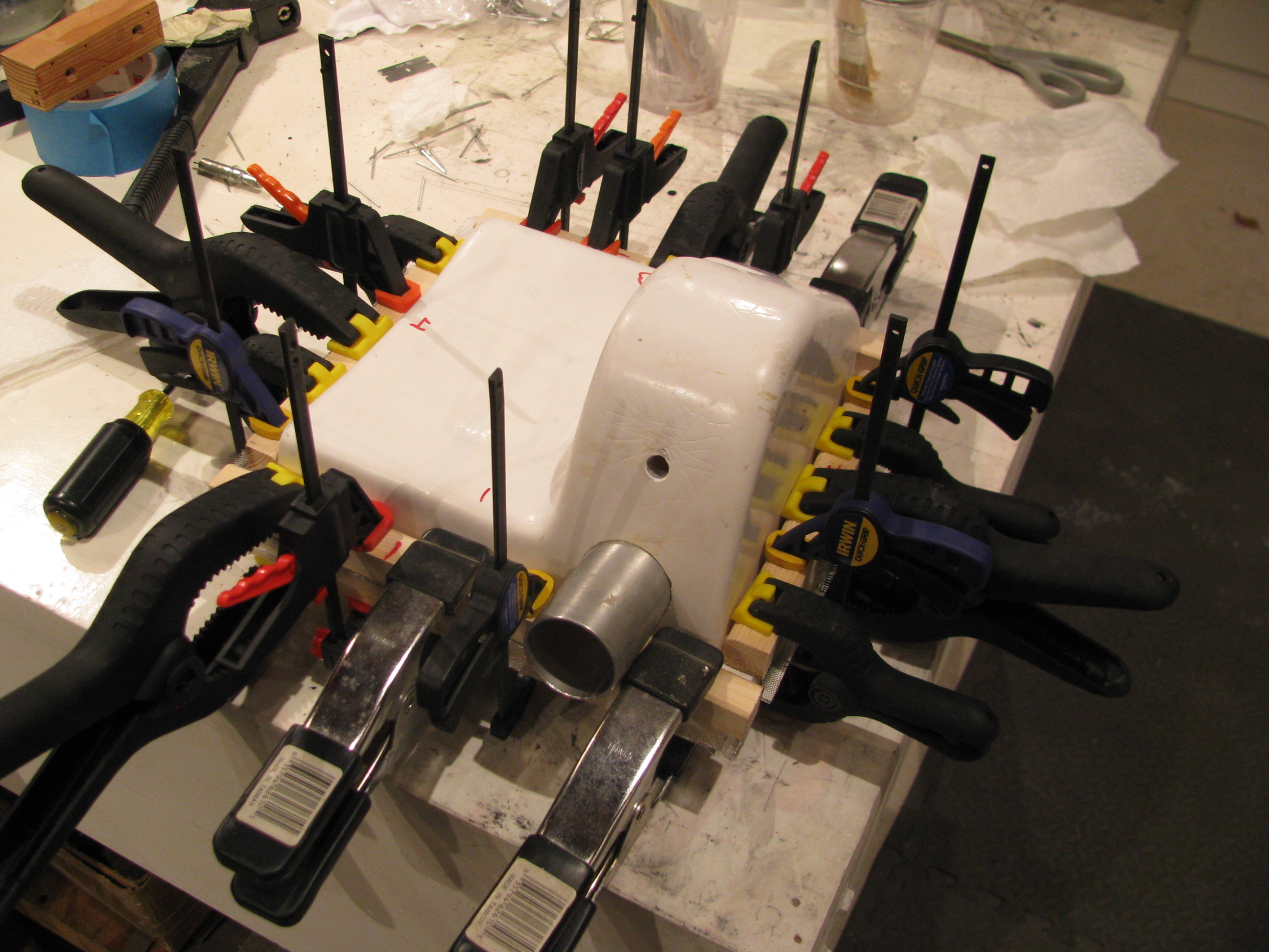
Fiberglassing together tank halves. Tidy up the insides (some stray bits of glass and cloth needed trimming, clean the surfaces with acetone, and bond the sides with a thick mixture of flox and resin.
Check for extrusion out each edge and clamp the hell out of it.
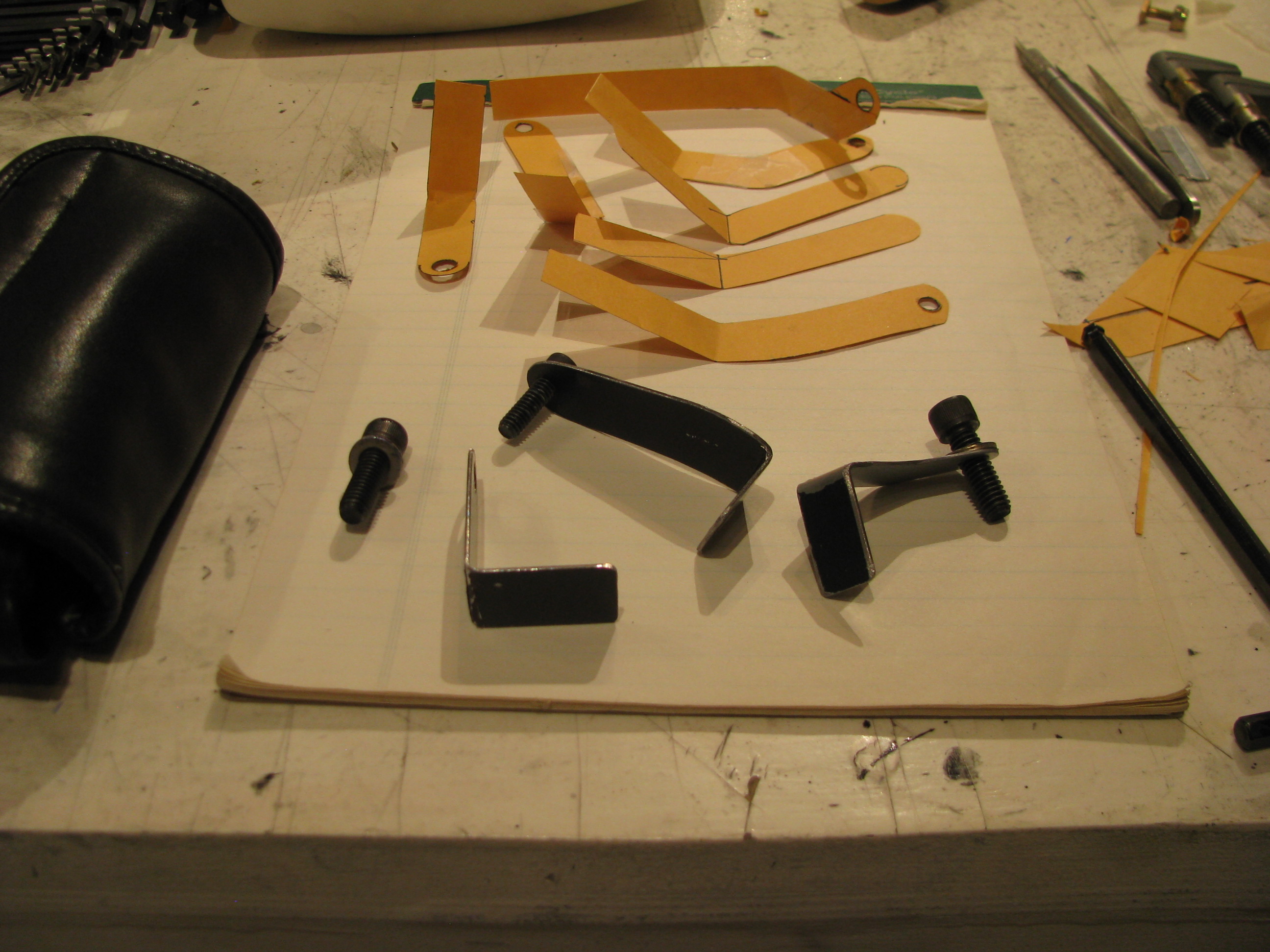
The tank mount brackets. You can see my many trial cardboard templates.
Thankfully I had an old ZVBox case that was 0.048” steel which I could use as a donor since there really isn’t enough steel strapping supplied to make the brackets, especially in the weird shapes you actually need, as opposed to the nice straight ones that BJ shows.
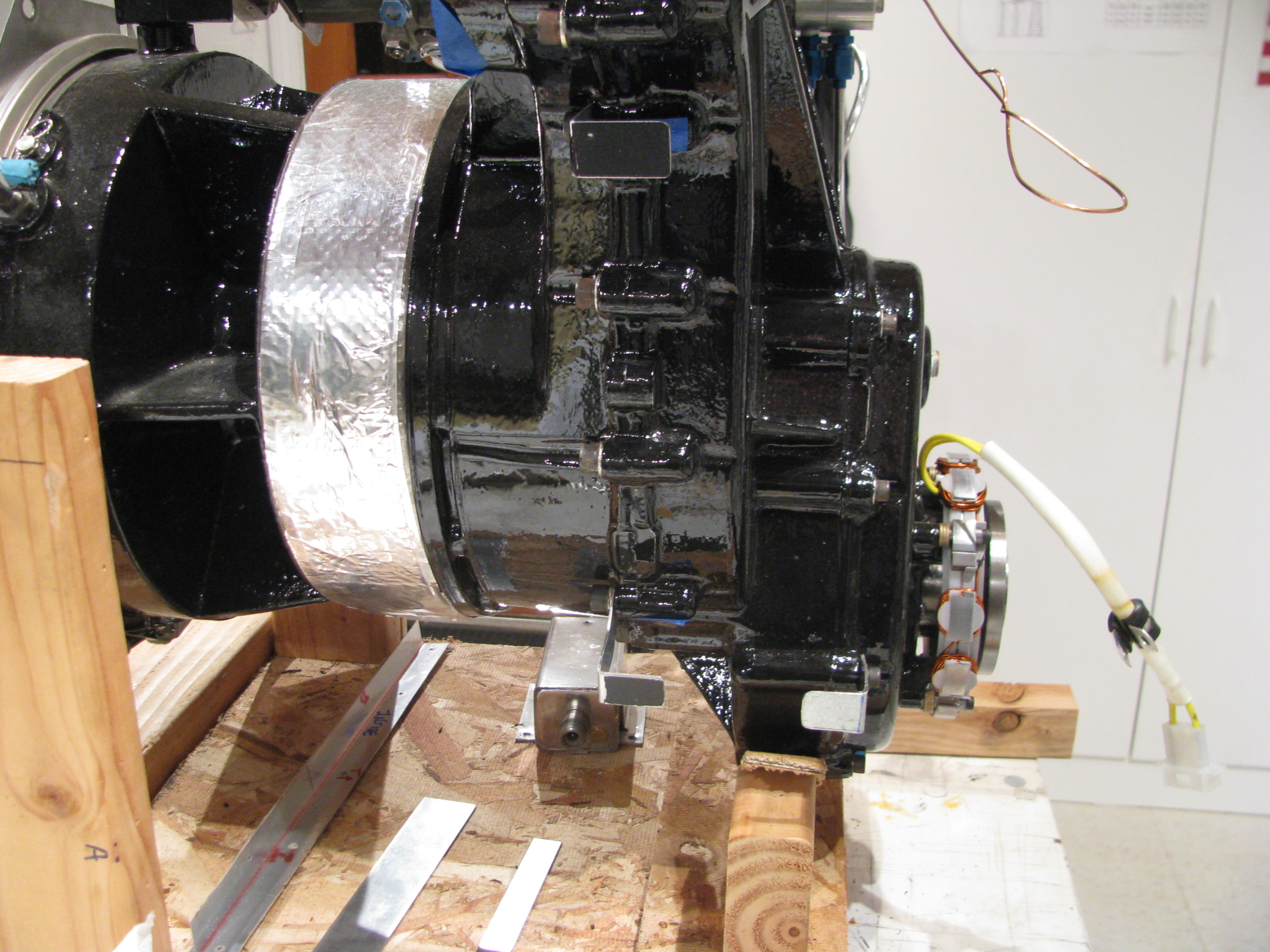
The videos show only two mounting points, top and bottom. I added a third using the one of the lower forward case bolts as the mount point. This takes it from something that could vibrate with some play to being very, very rigid to the engine.
There are a few points in the instructions like this, where it seems a very simple mod can add immensely to the strength/quality. I am sure I’m not the first to do this.
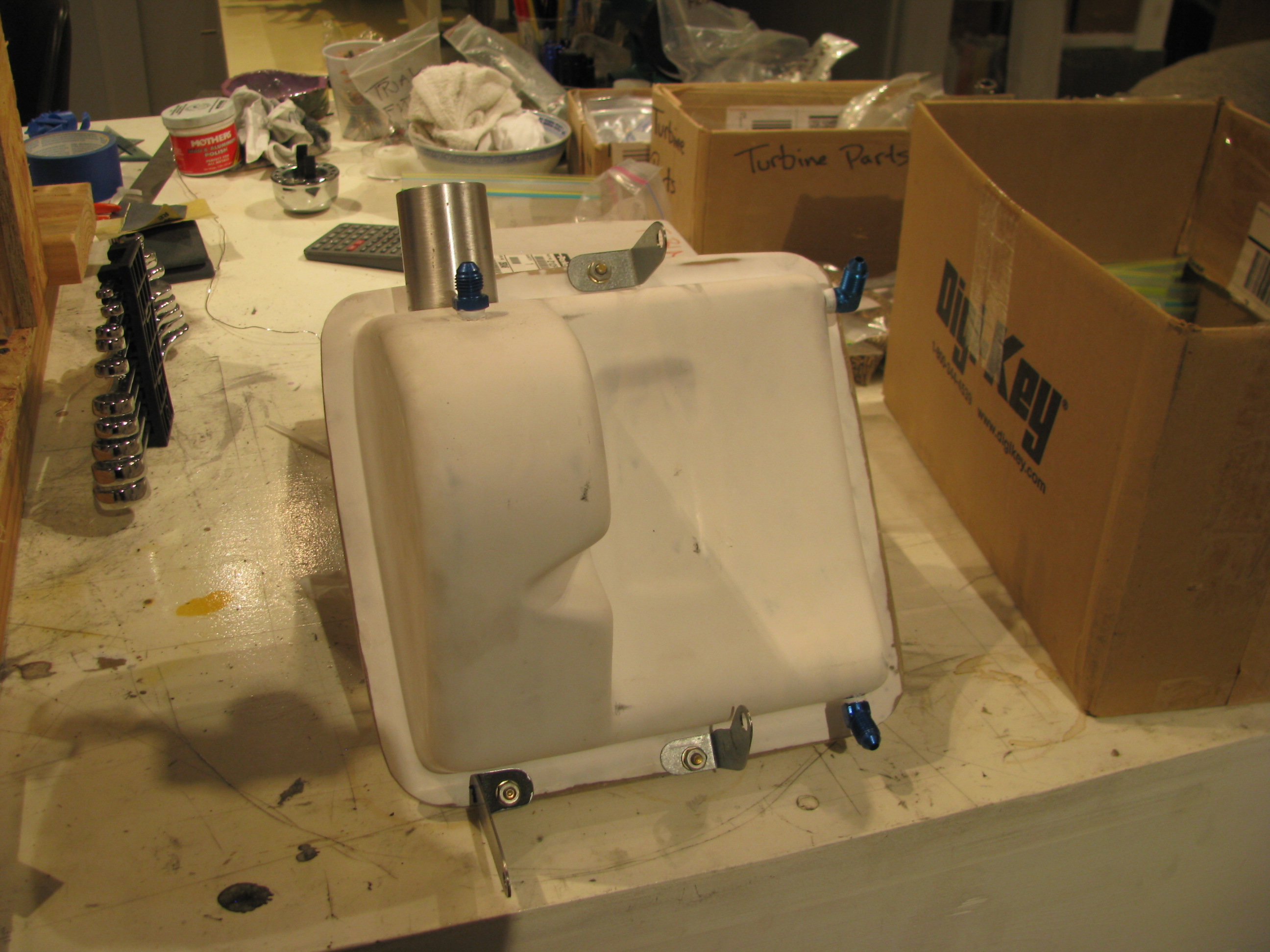
Finished tank with fittings mounted. I glassed the tank in the fall, but only just now finished mounting it this spring. My long winter of distractions, international travel, and business has ended and I plan on making very good progress on the helicopter again.
Turbine Prep
09/29/12 14:13 Filed in: All
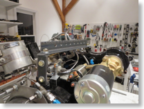
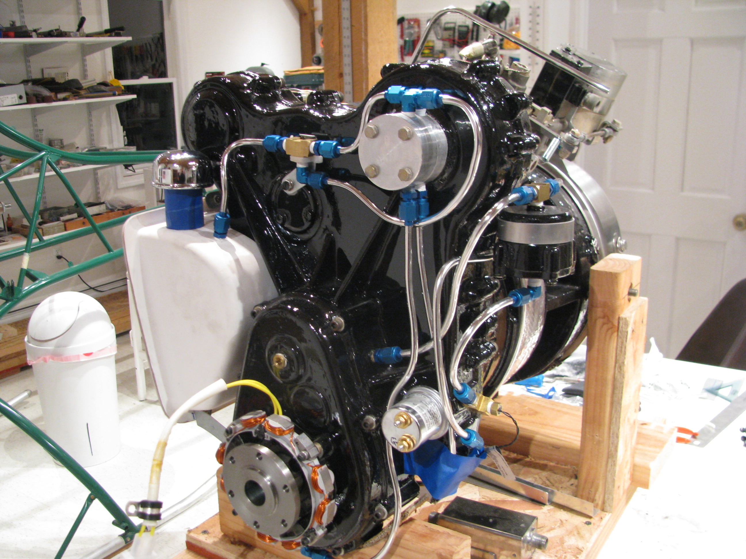
Back to turbine prep. Summer is over. Time for serious building. Adding the numerous fittings and prep for the plumbing. While at Reno I saw N168SK, a Helicycle belonging to James Kent, which was out on static display. Wow! A beautiful machine and represented the breed well.
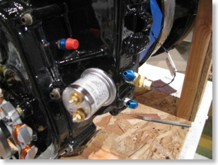
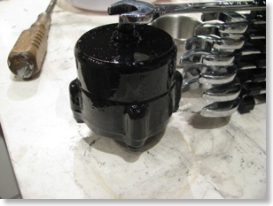
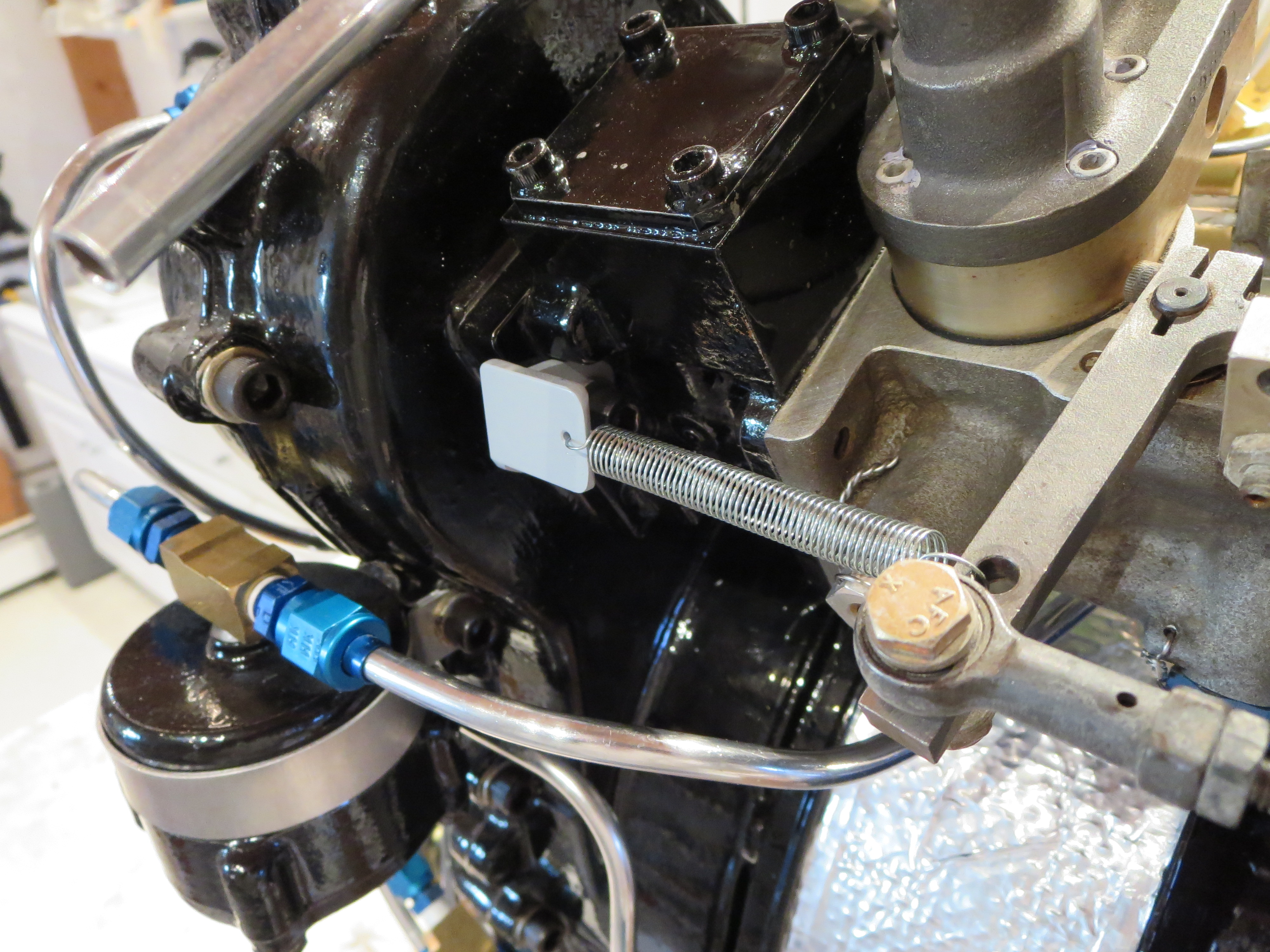
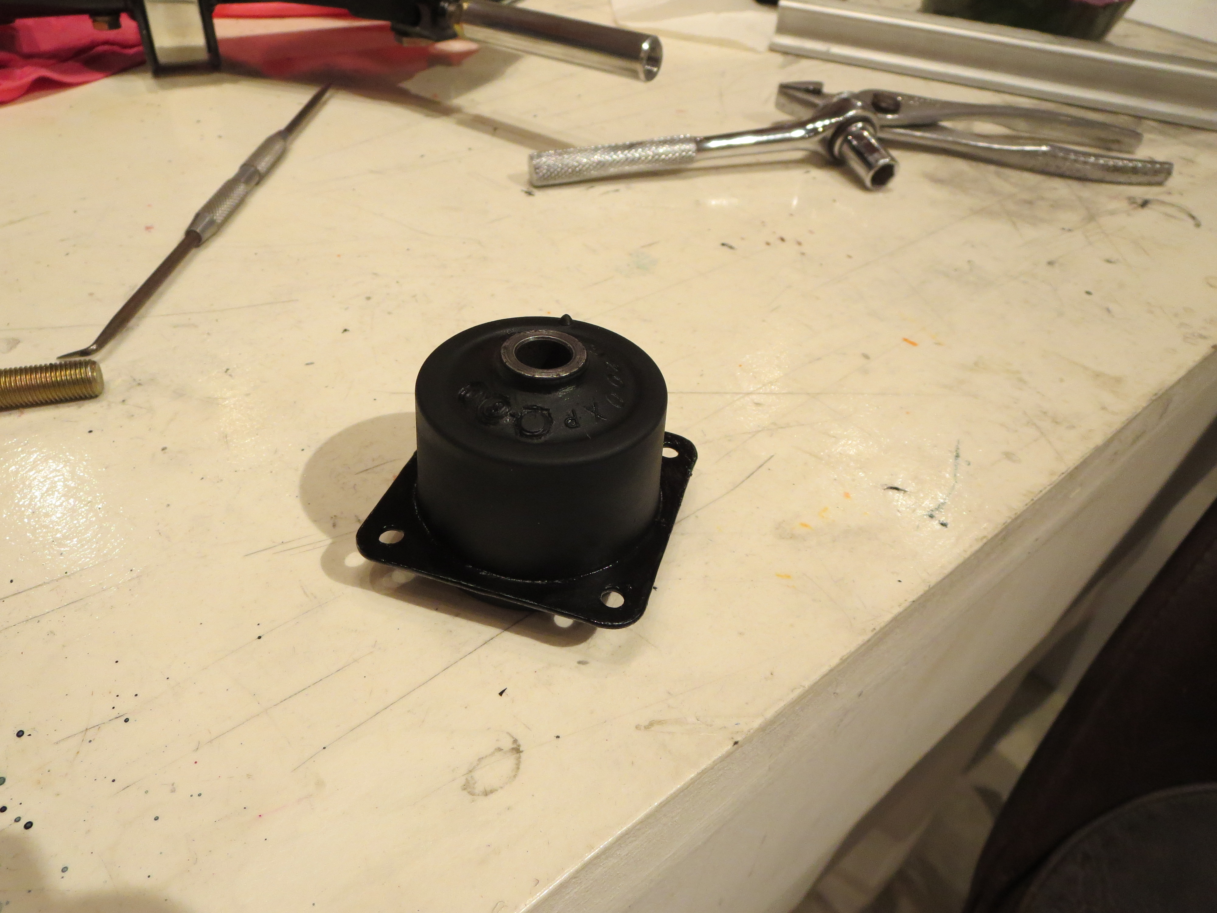
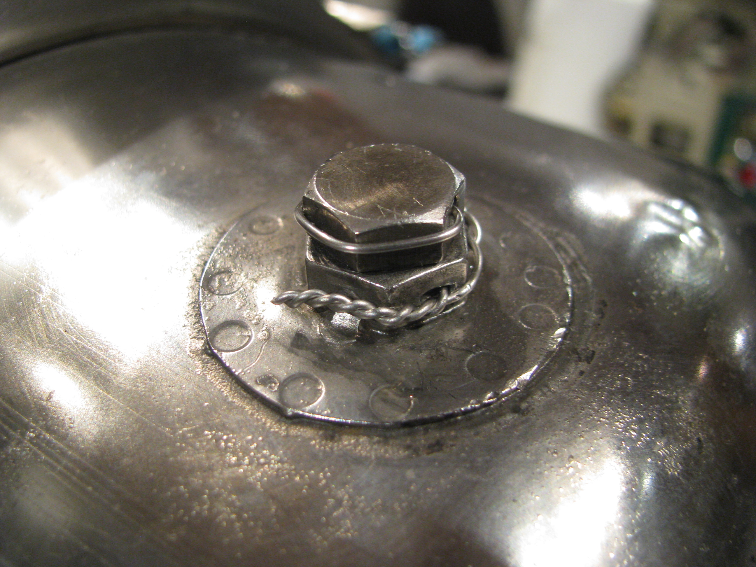
Various plumbing fittings, safety wiring, and painting of the oil filter housing.

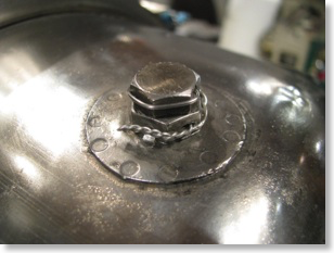
My first oil line. I think I may have “overflared” the ends as a little ridge extruded out between the flare clamp dies which prevents the retainer ring from seating fully. This one is coming back. I practiced on a couple, but probably should have intentionally under and over flared to get a feel for what that looks like, Again, my second helicopter will be perfect.
Takes about 3 minutes to polish the line and makes a huge improvement in appearance.

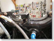
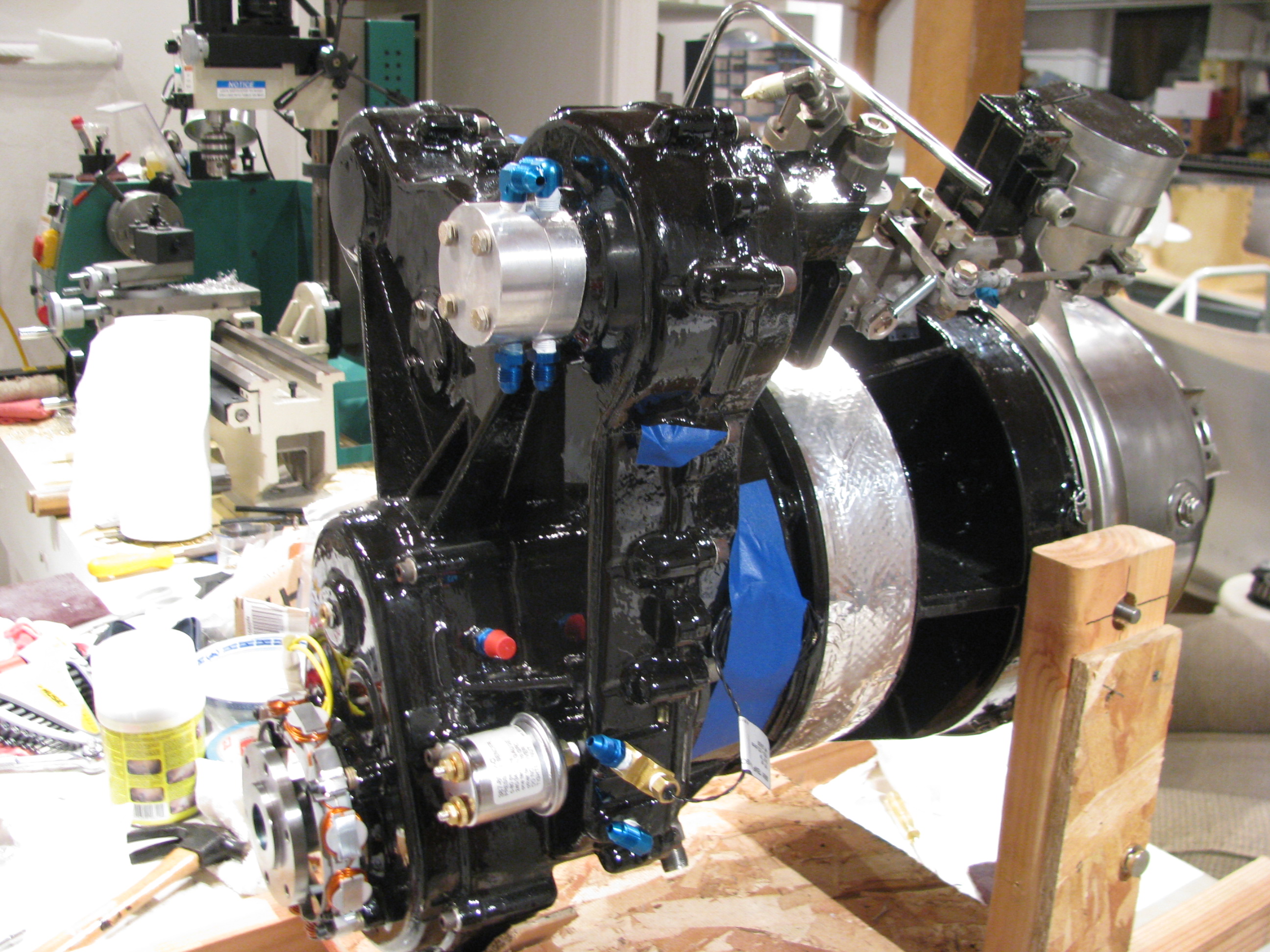
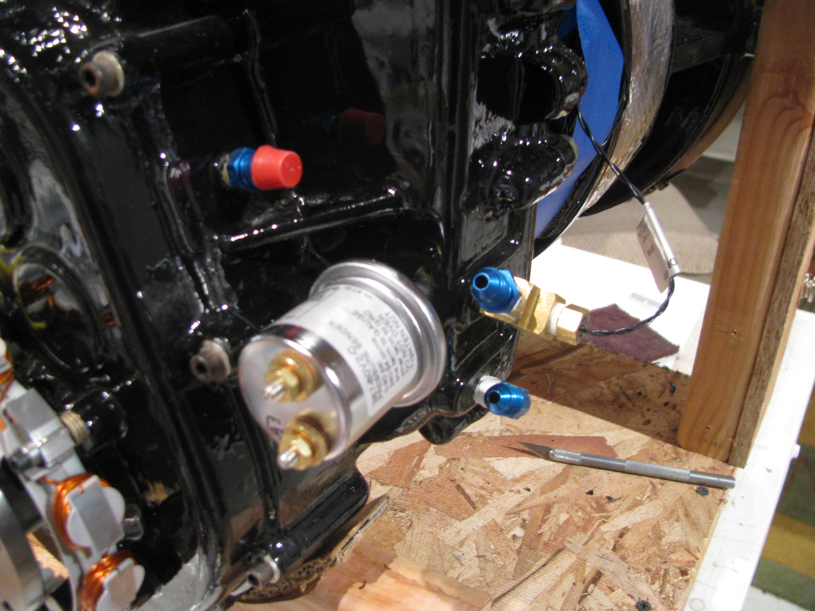
Adding more lines. Engine is tilted up for better access to lower lines.
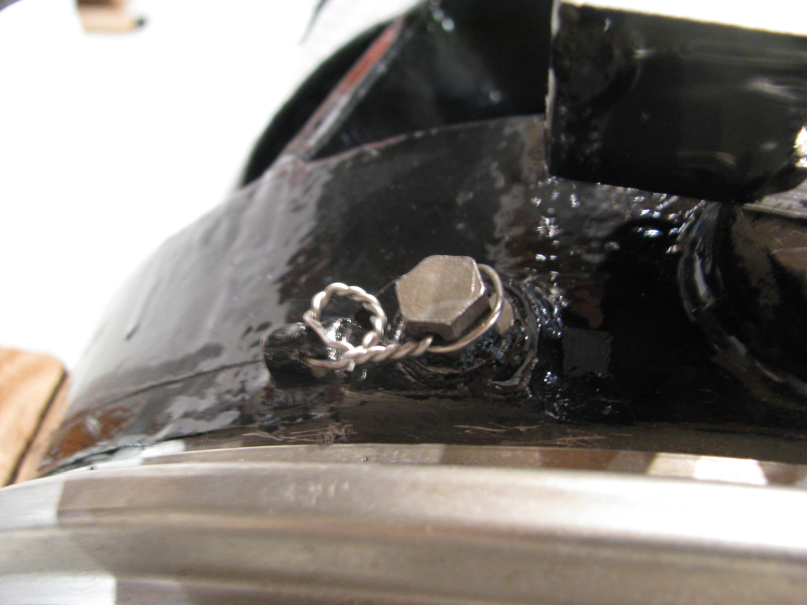
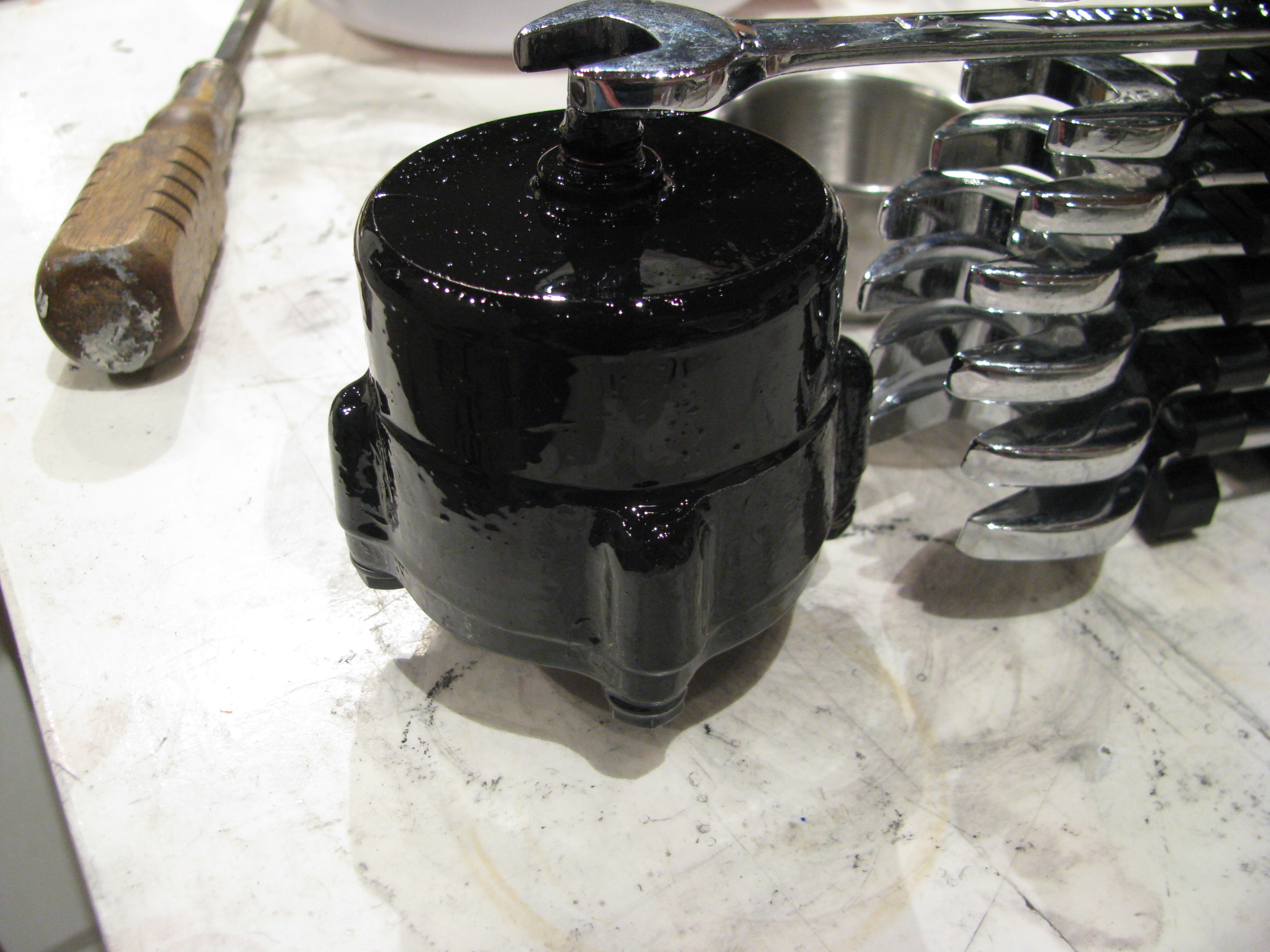
Various plumbing fittings, safety wiring, and painting of the oil filter housing.
My first oil line. I think I may have “overflared” the ends as a little ridge extruded out between the flare clamp dies which prevents the retainer ring from seating fully. This one is coming back. I practiced on a couple, but probably should have intentionally under and over flared to get a feel for what that looks like, Again, my second helicopter will be perfect.
Takes about 3 minutes to polish the line and makes a huge improvement in appearance.
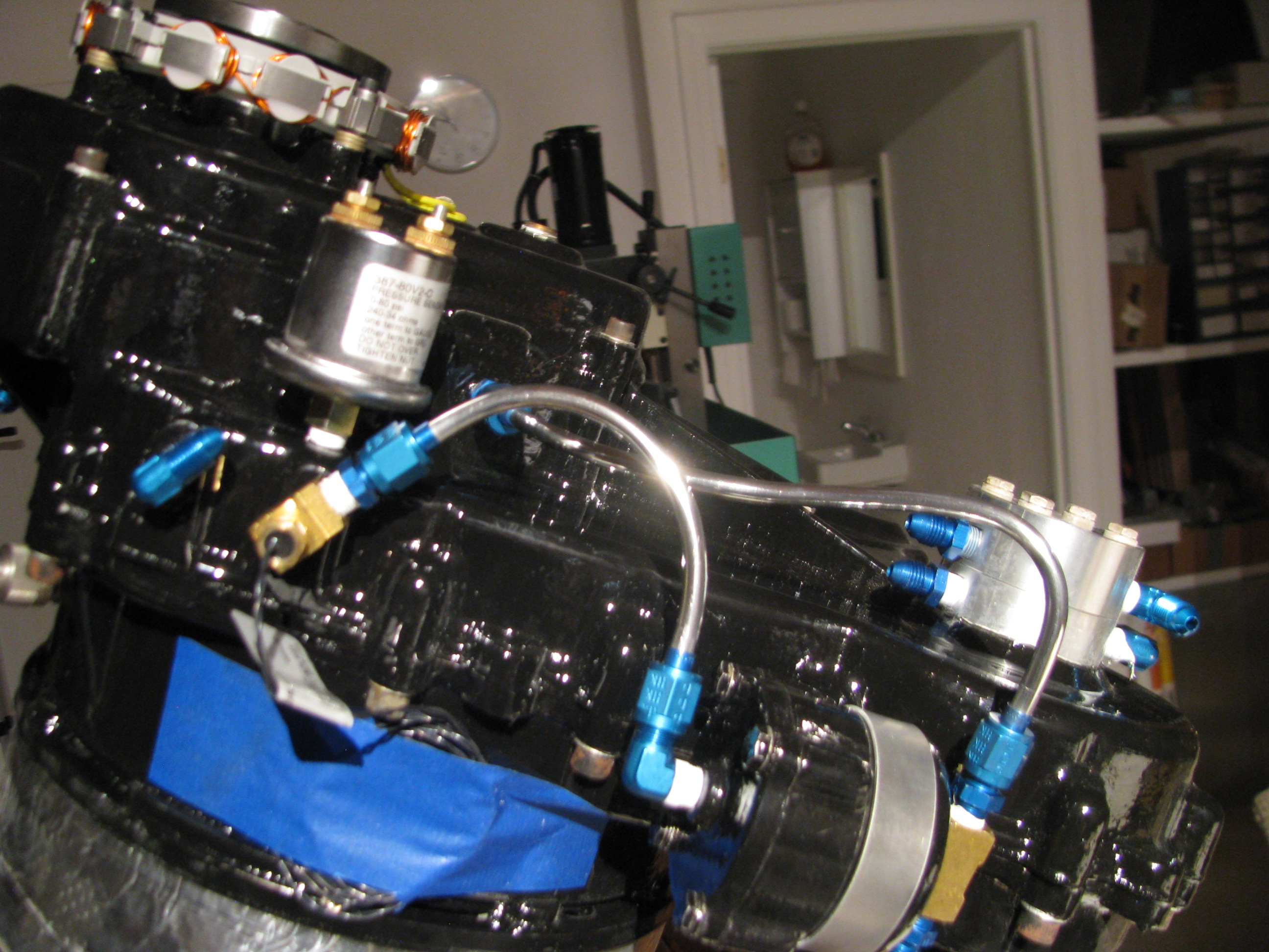
Adding more lines. Engine is tilted up for better access to lower lines.
Bracket Repair
06/08/12 14:12 Filed in: All
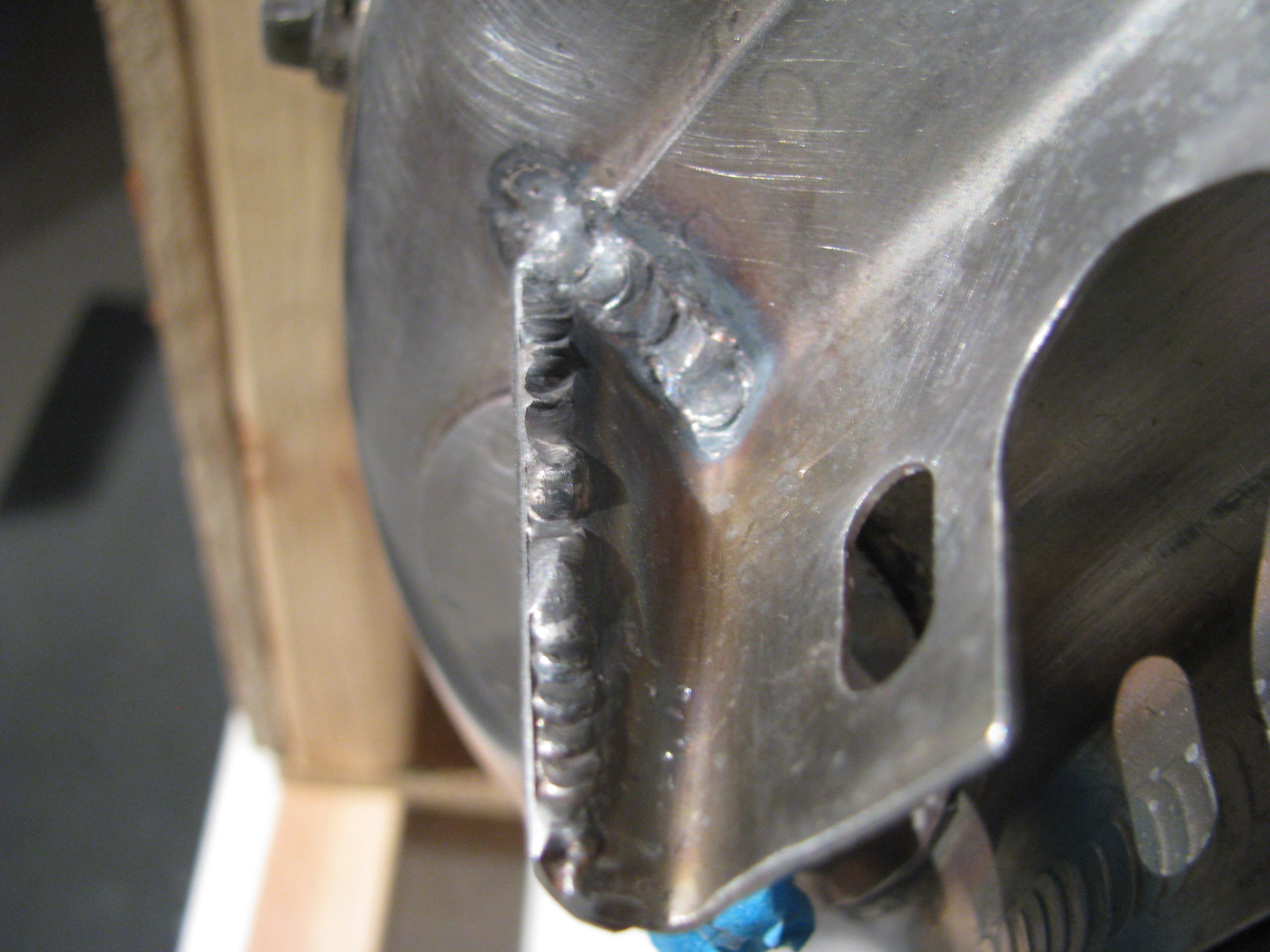
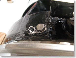
Picked up my turbine from my mechanic. The crack on the manifold bracket was welded with a little doubler to strengthen it. Much stronger and straighter now.
Engine Stand
05/28/12 14:10 Filed in: All
Not much happening here. I built a dolly to carry the turbine out so I can take it to be welded on the fuel manifold bracket.
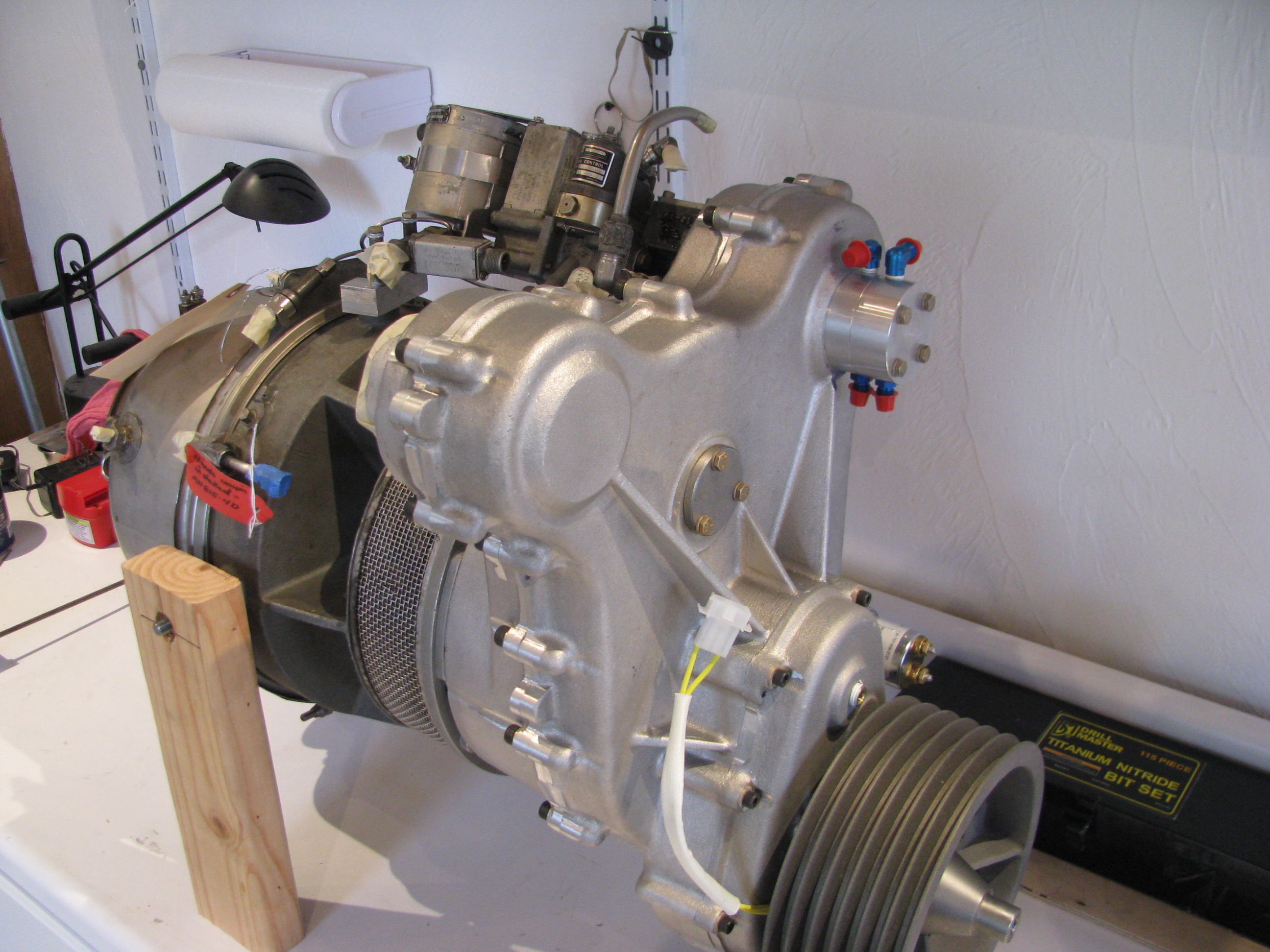
POR15 Engine Painting
05/06/12 14:07 Filed in: All
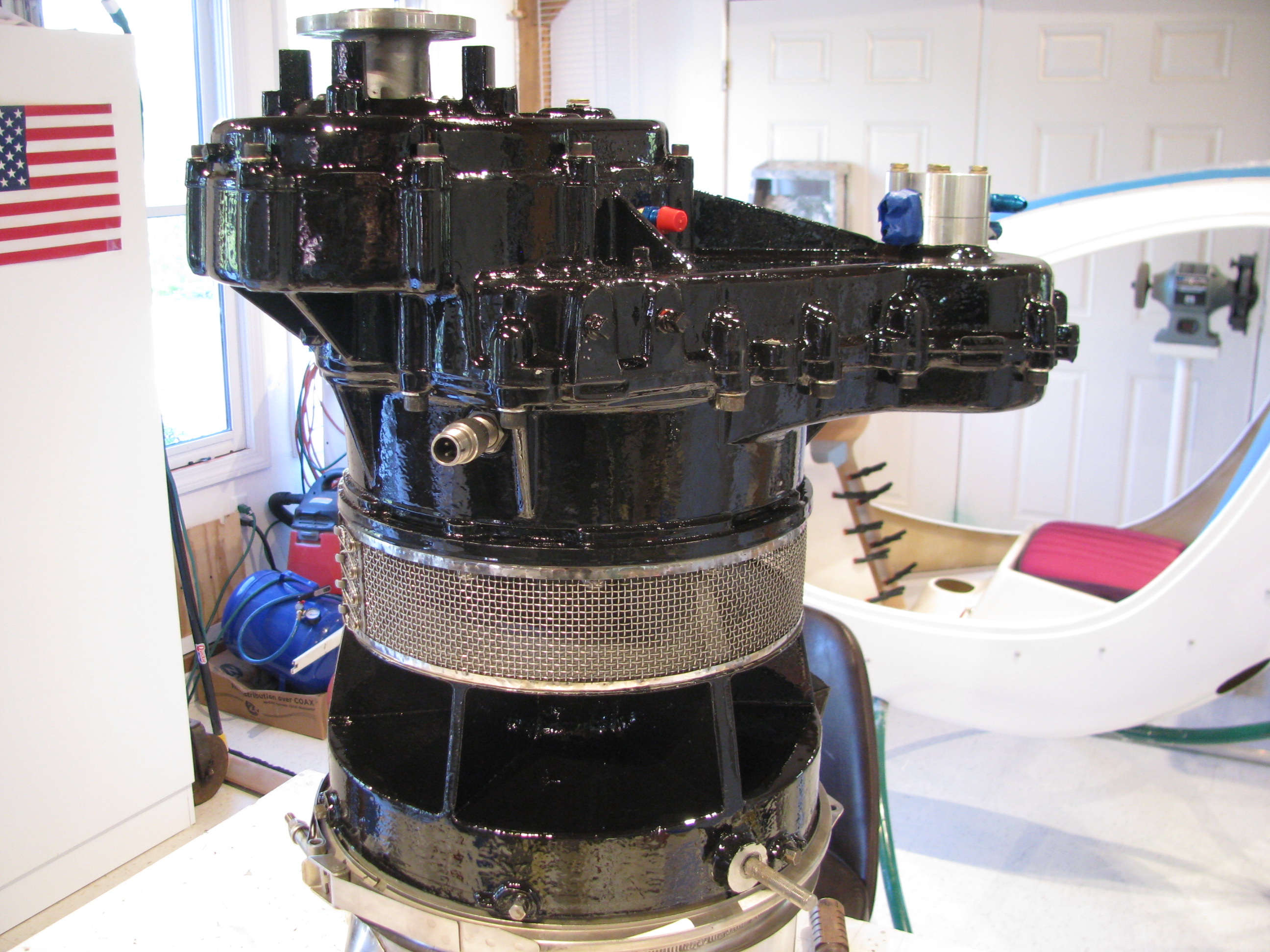
The engine has been painted with POR-15 gloss black. This stuff is really shiny and flows out oh so slowly.
The most time-consuming part was masking all the heads of the allen head bolts. That took forever and then was painful to remove as the POR really grabbed the tape.
I had to touch it up with an artists brush after removing the masking tape. but it’s finally done.
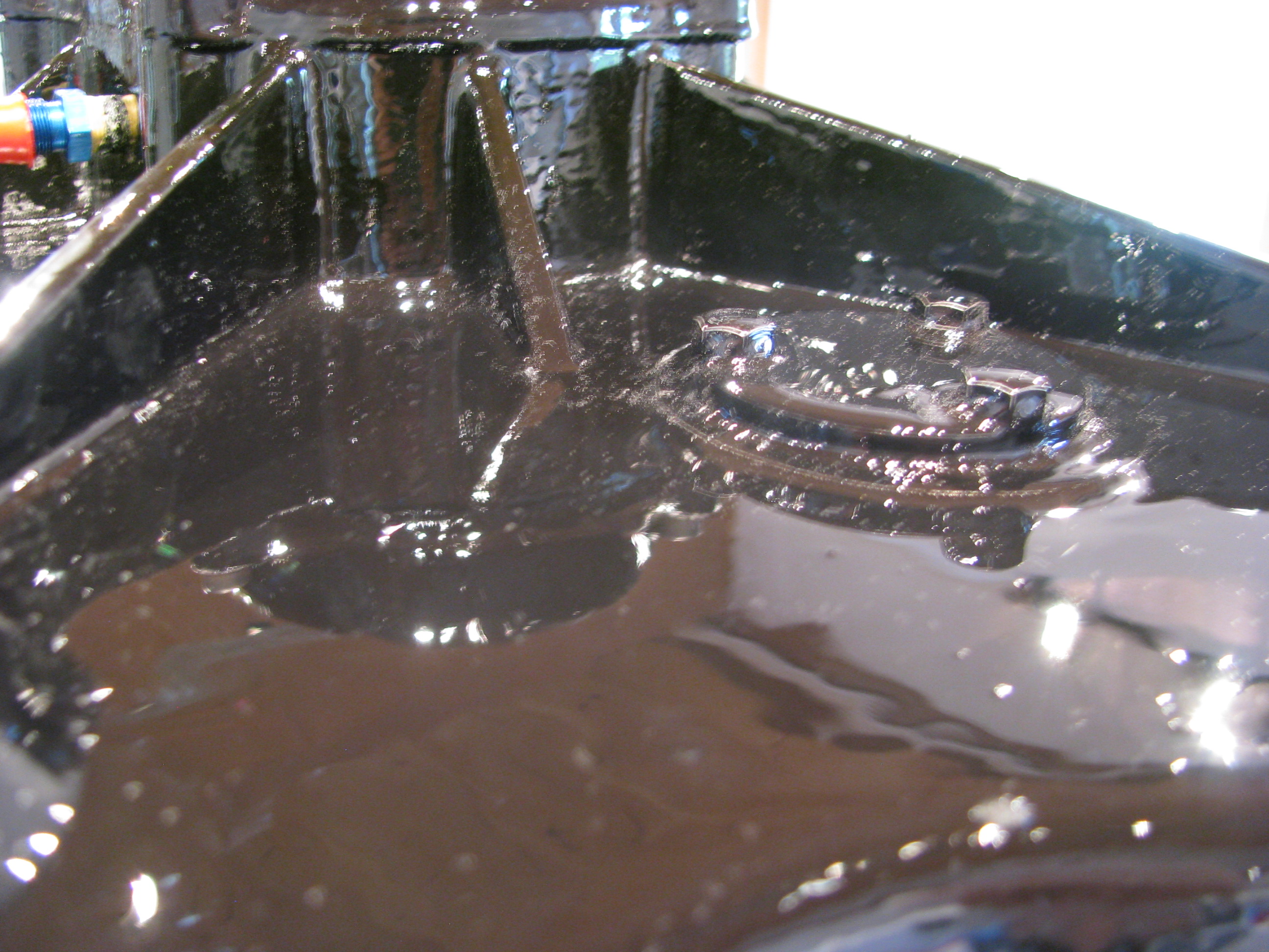
The POR-15 flows out very slowly. I can’t believe this is a brushed-on finish.
Now this is a rough casting, so I was not expecting a show quality finish, and it isn’t, but overall I a pleased with the outcome. The paint flowed out evenly and the brush marks disappeared.
It appears to be a thick, tough finish.
Cracked Manifold Bracket
04/30/12 14:05 Filed in: All
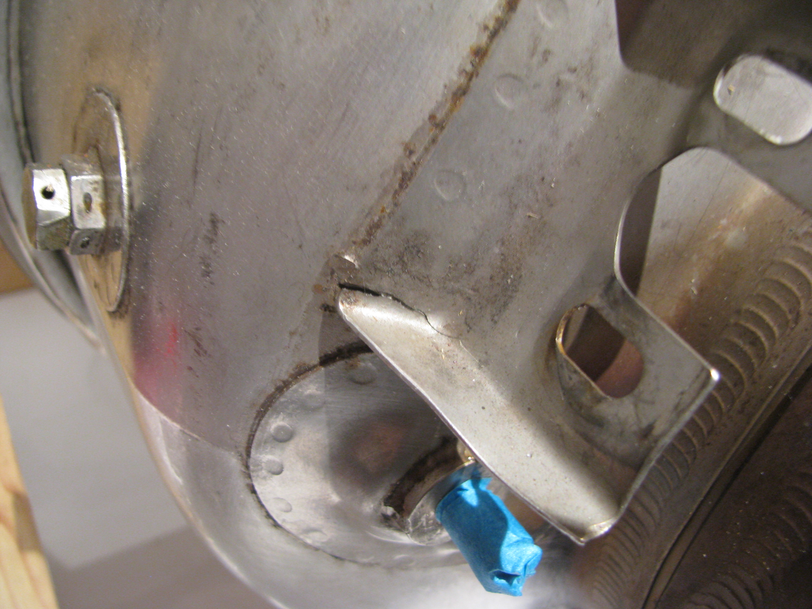
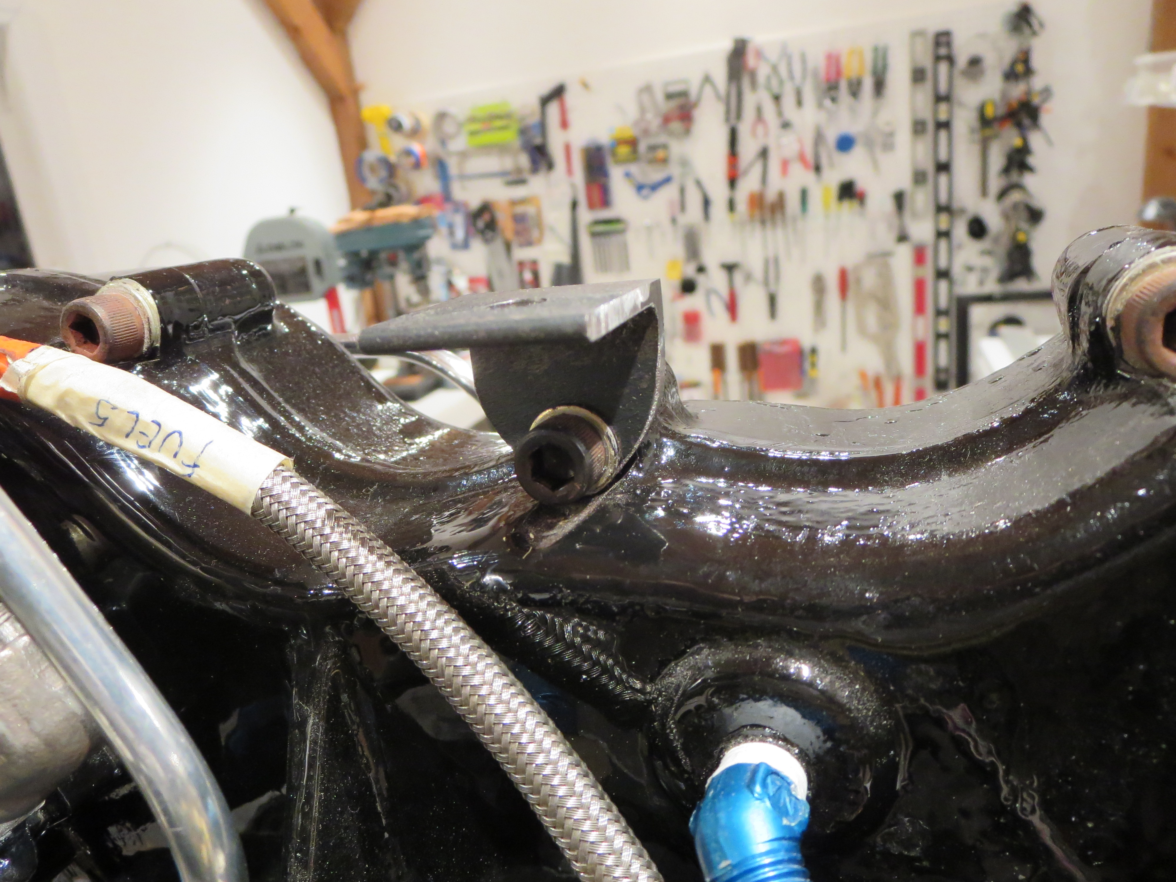
One flaw I noticed was that the bracket on which the fuel distribution manifold is mounted is cracked. You can just see the crack in the bent angle of the bracket. I will have to have this rewelded before the engine goes in. It really wasn’t evident until the manifold was removed, so I can’t really get down on Eagle for this. I will truck the engine over to my airplane mechanics to be repaired before starting re-assembly.
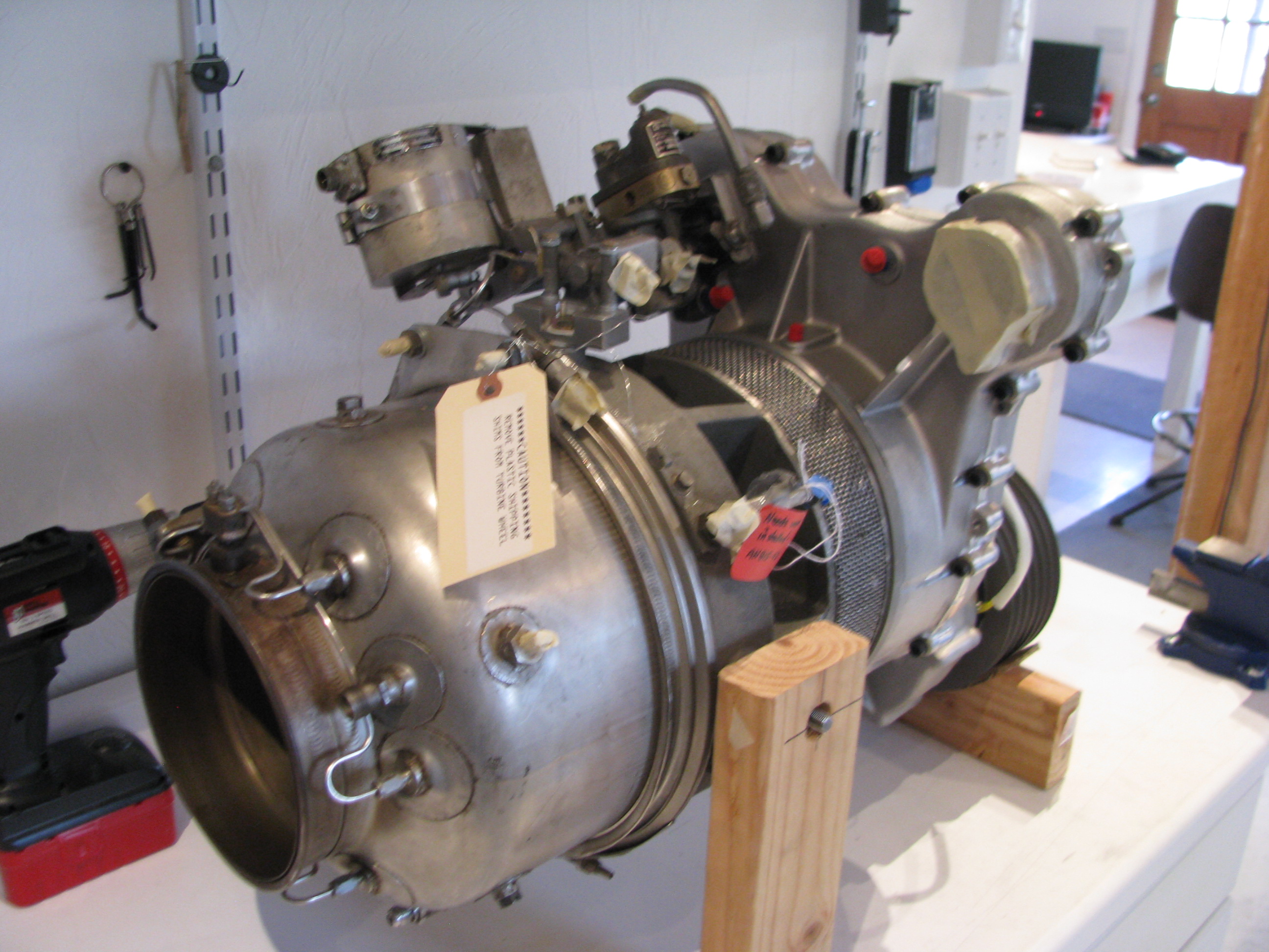
Stripped Turbine
04/08/12 14:00 Filed in: All
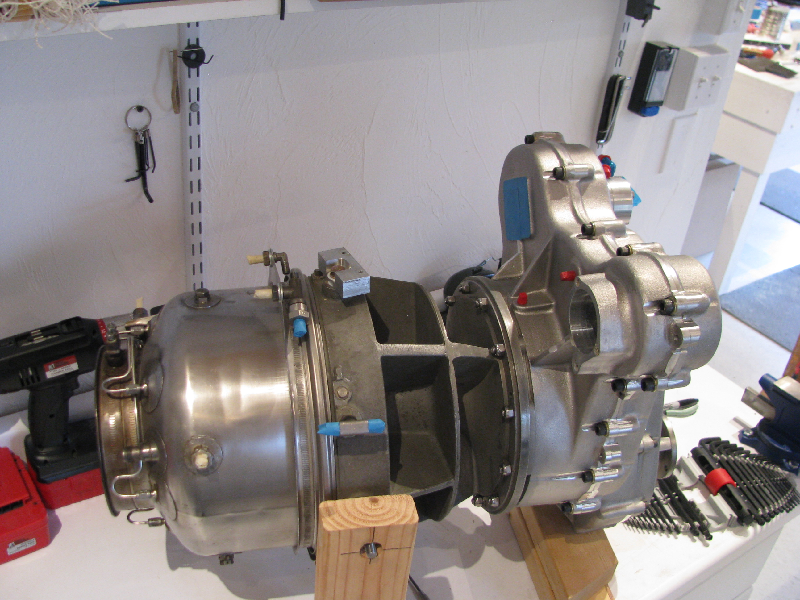
Nearly fully denuded. I am going to remove the fuel injection manifold as there is quite a bit of corrosion in the area where the tailpipe clamp goes. Mainly cosmetic, but it looks pretty bad. It will also allow for more shining up of the burner can. 10 minutes on that top section and it looks OK.
I’ve ordered some black POR-15 to paint everything but the burner can. I would have used clear, but that center section is so discolored that there is no way I could get it looking good.
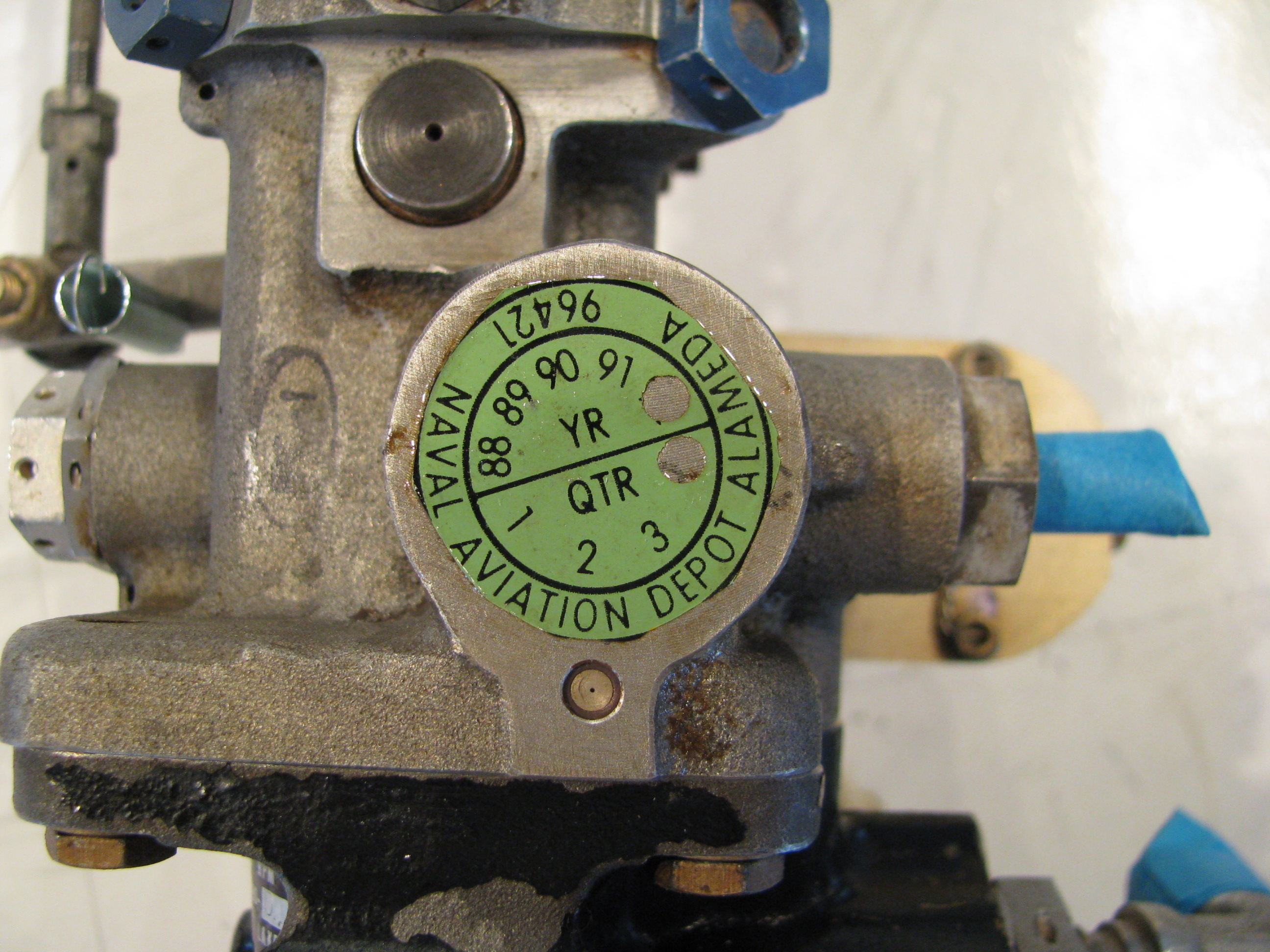
A clue as to the past life of this turbine.
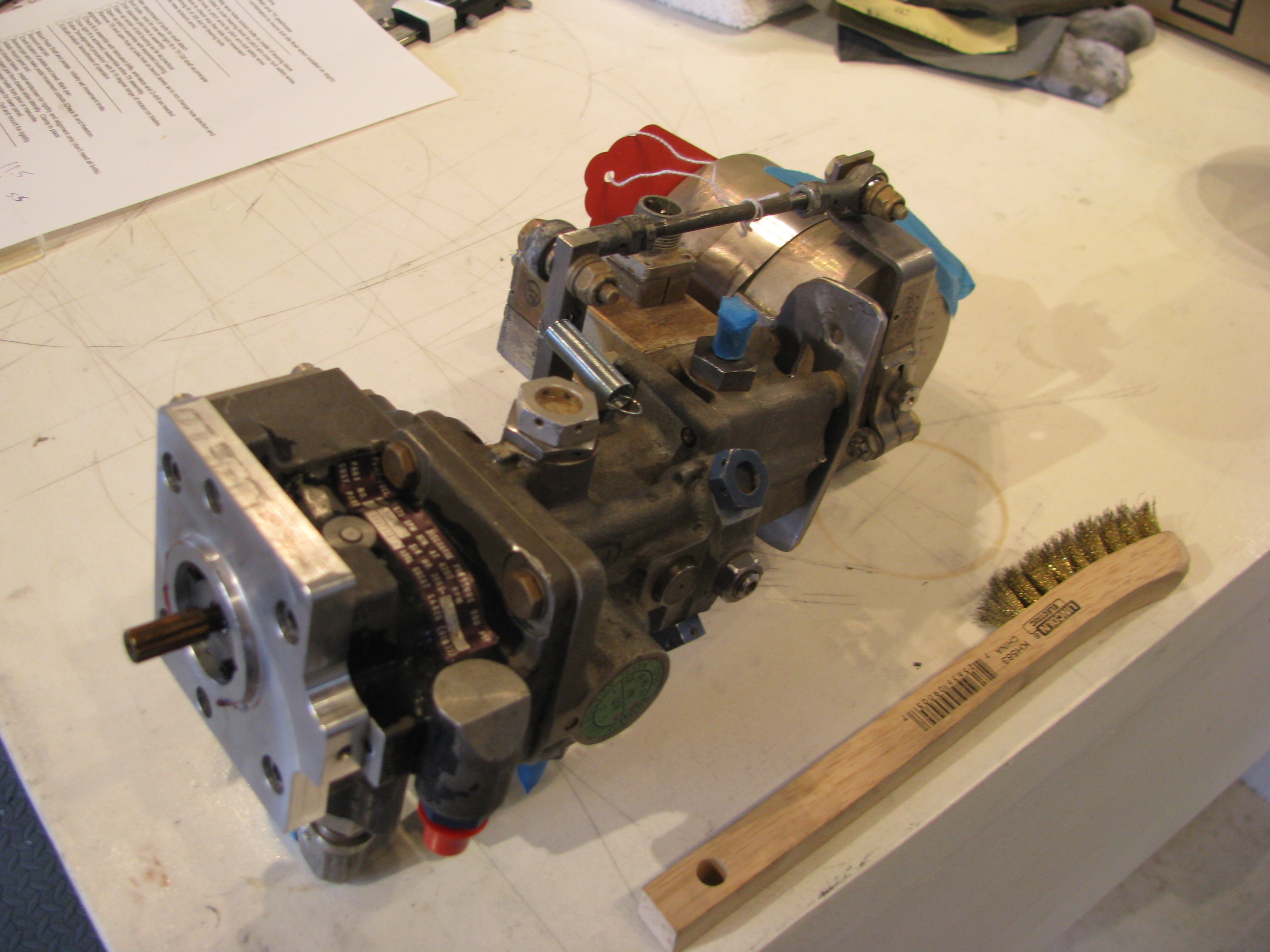
This is the fuel pump/control unit. That arm on the top is the infamous “delicate” throttle control arm. It is kind wimpy looking, but not tragically so. The surprising part is that the full travel from stop to stop is only about half an inch.
Though it is looks pretty tired, I am going to resist the temptation to take it apart to clean and resurface it. I’m quite sure that I would do more harm than good. It’ll just get cleaned and brushed off as an assembled unit, then reinstalled.
Speaking of more harm than good; BJ makes a point of having you make tick marks on the pulley and the mounting flange in the front of the gearbox to maintain alignment prior to removal. I did not realize that the conical center section is a piece separate from the pulley. I made my tick mark on the pulley, but when I pulled it off the shaft, the centering cone dropped out to the floor. I stared at it for 15 minutes to see if there was any hint of which position it was oriented in (1 of 6) by virtue of any witness marks on the mating surfaces, but could not. I will have to figure out where BJ was measuring when he said they were indexed to 0.003 to 0.005 of runout and remeasure to establish the orientation. Poop. This is my first mistake in a while caused by just not watching the videos closely enough.
Turbine Install Start
03/31/12 13:49 Filed in: All
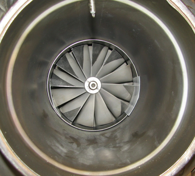
The Helicycle is powered by a Solar T62 turbine engine. It’s one of the primary attractions of this helicopter design. The T62 was designed as a ground power unit for the military for electrical generators and is used as the APU on a number of aircraft, including the CH47 Chinook.
In the Helicycle it is derated from its designed power output level of 160HP down to 90HP for reliability and longevity. Plenty of margin. Eagle R&D buys them surplus and refurbishes them including a teardown and dynamic balance.
As part of my effort to get multiple threads of effort going, I uncrated the engine and will begin tearing it apart in preparation for painting and mounting. You can see that I’ve started by removing the starter and a number of the fuel lines. Lots of pictures have been taken as each piece comes off and all the parts marked.