
Switch Labels
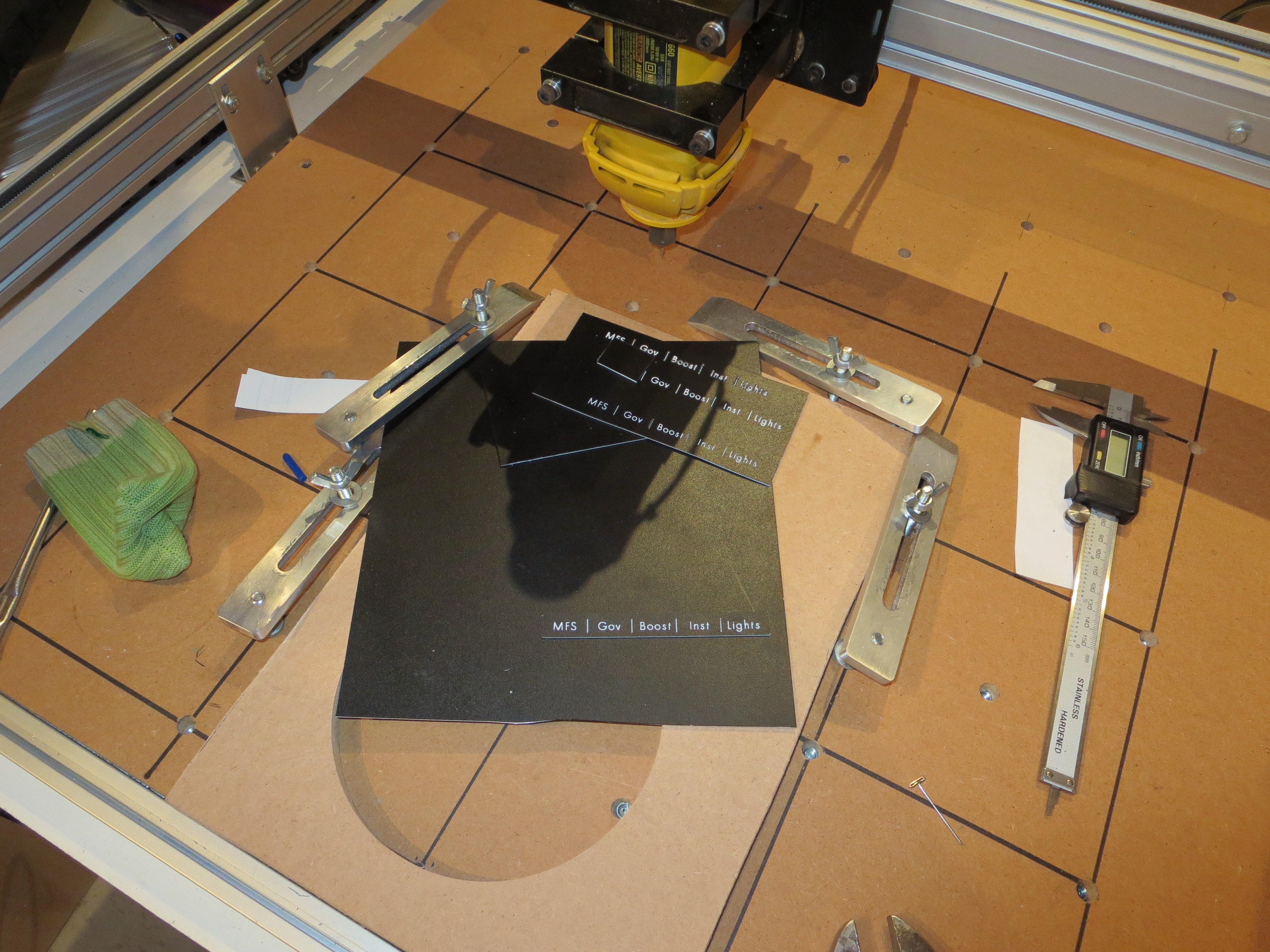
Paint the white sheets with a couple of heavy-ish coats of satin black, then route the labels with a very fine point engraving bit. It took a couple of tries to get the right bit and the correct depth, but I am quite satisfied with the results.

Since I have the detailed CAD for the panels I can easily come up with shapes that surround the entire switch area and are held in place by the switches. These are just test pieces, but I think I will go with this approach.
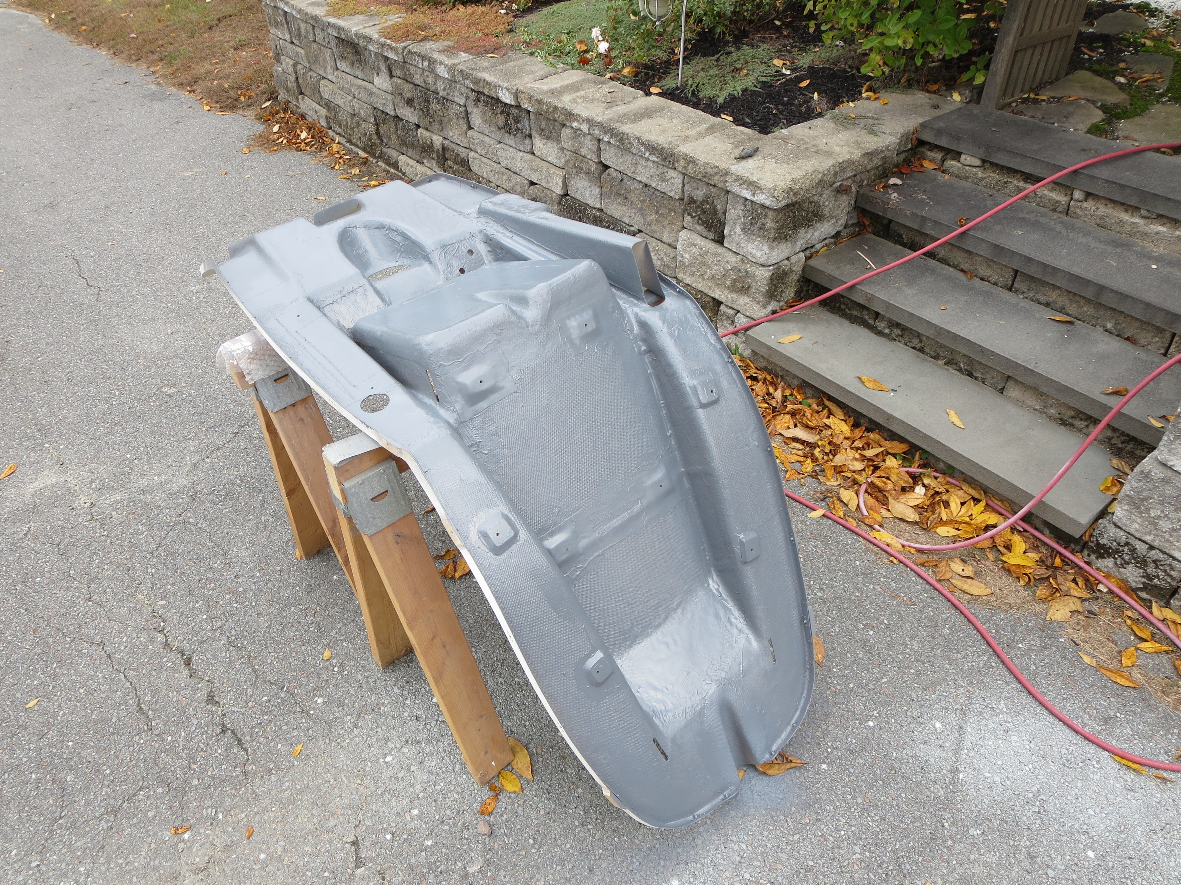
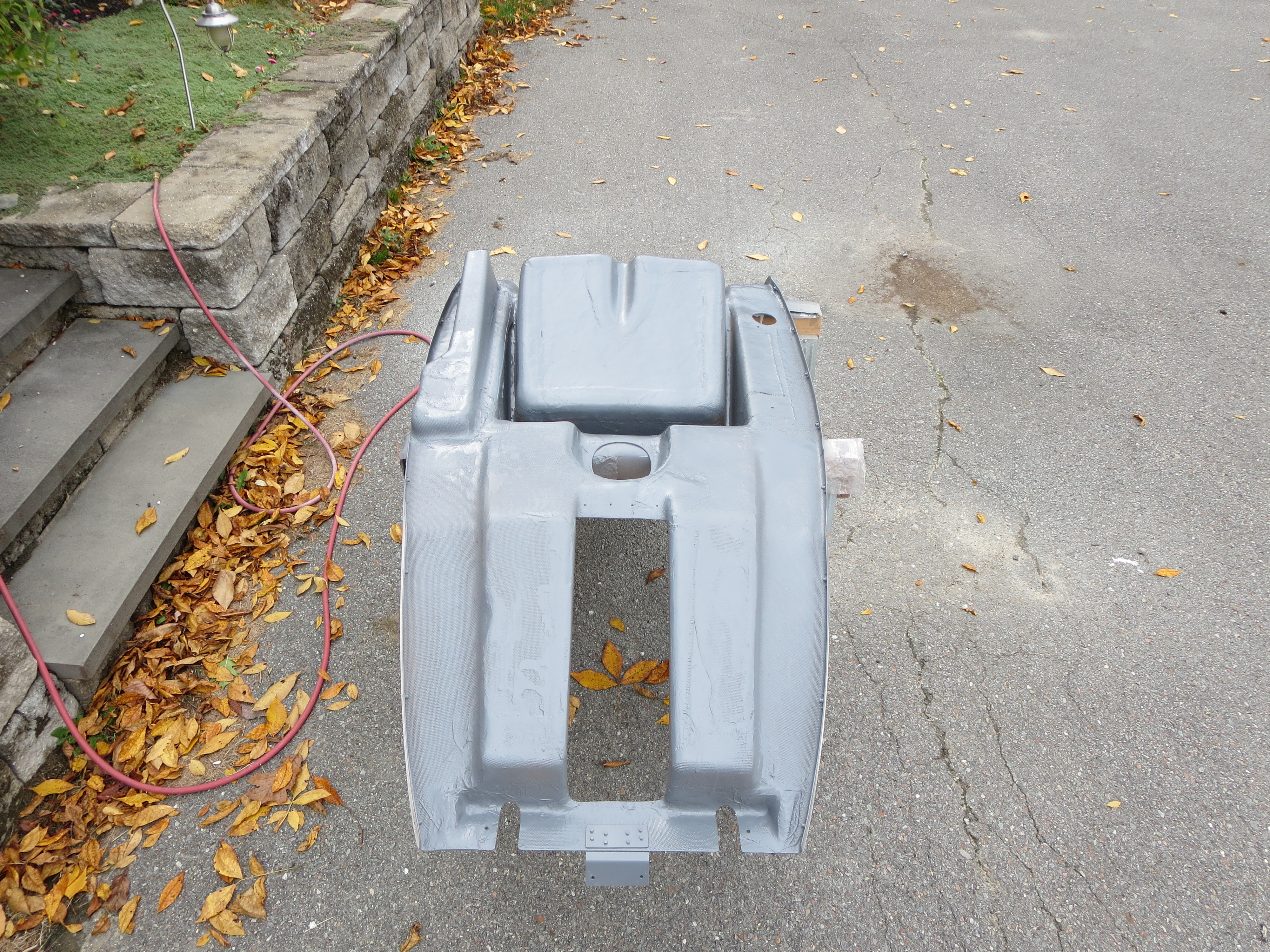
Cabin Interior painting
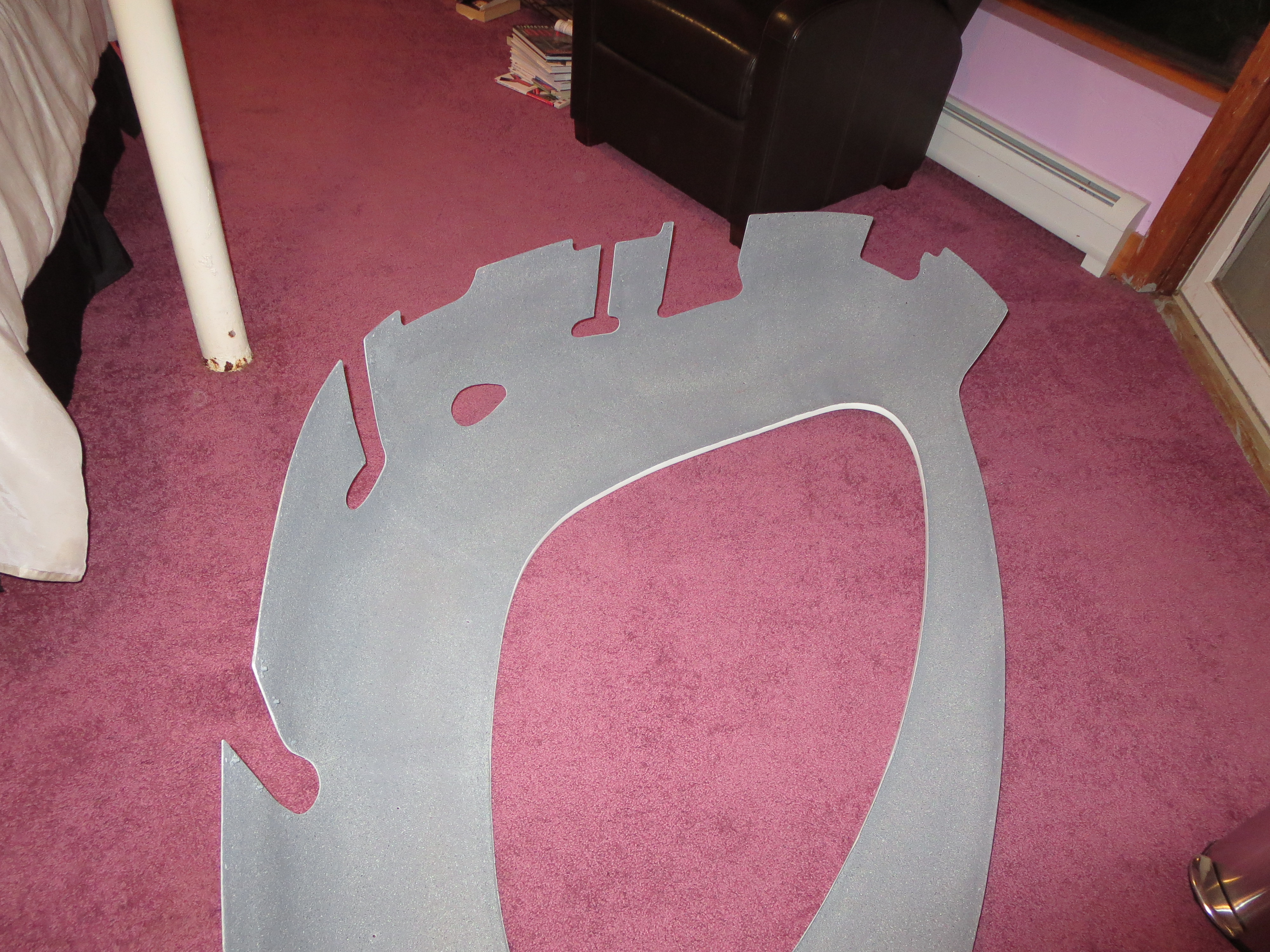
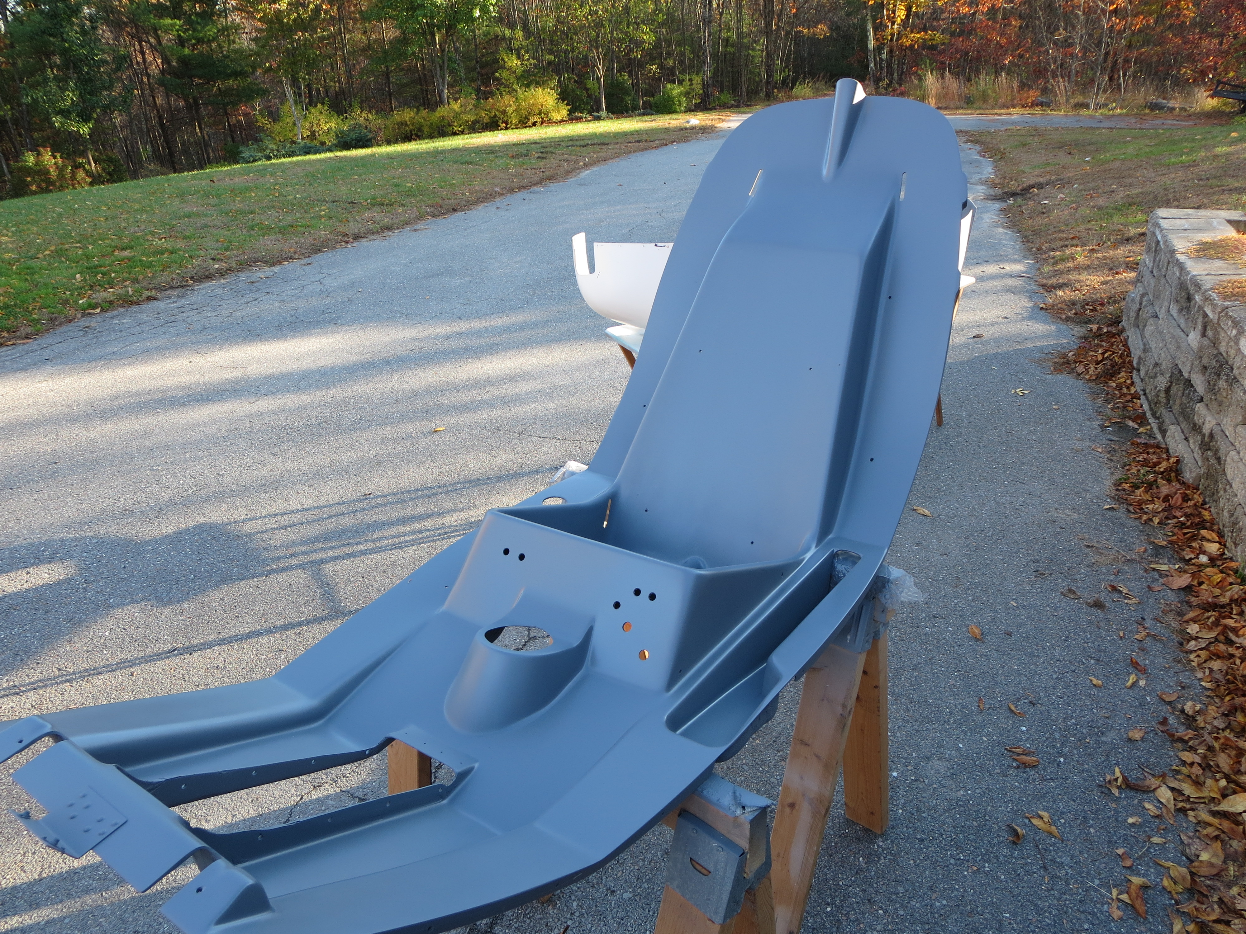
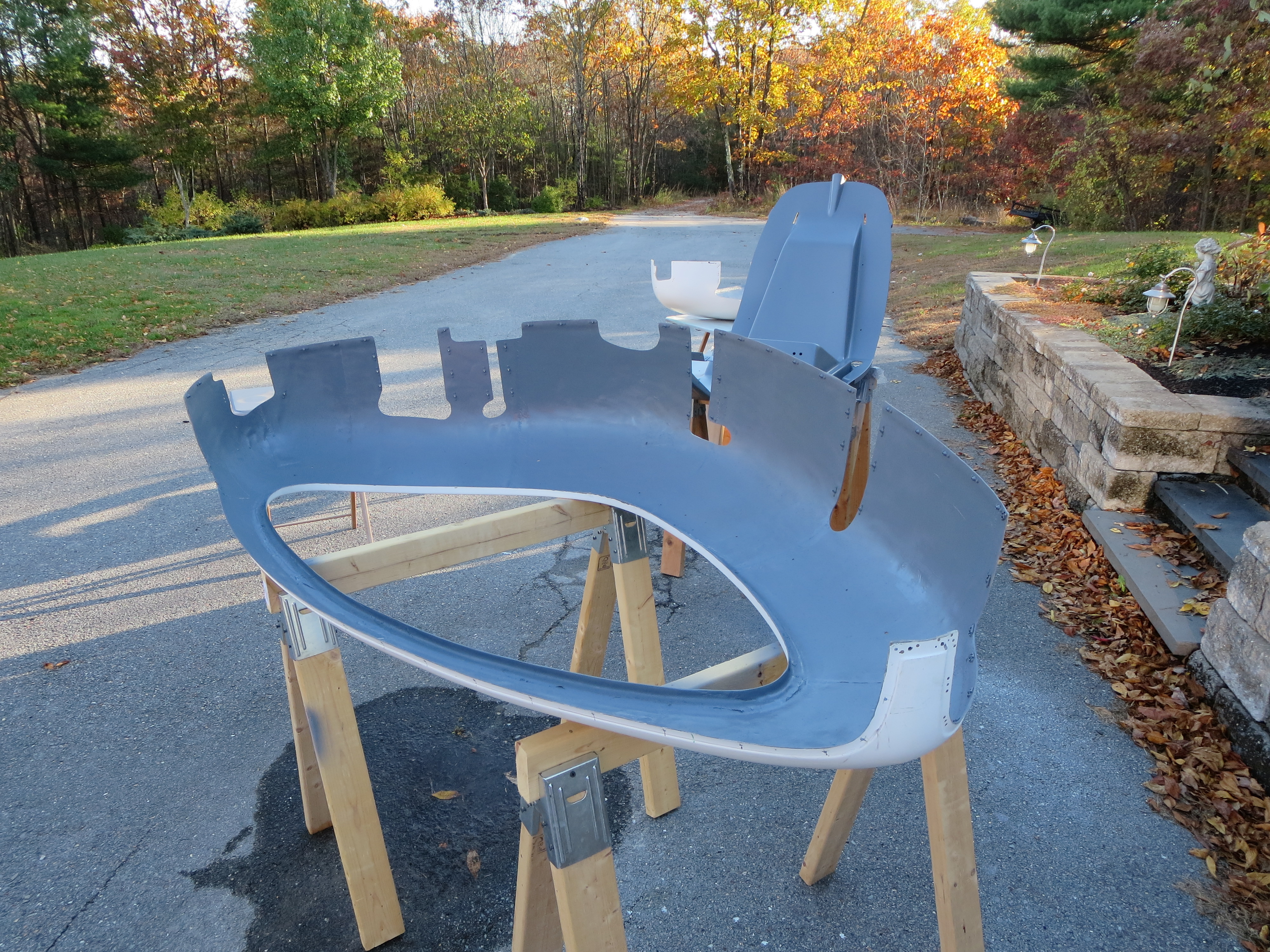
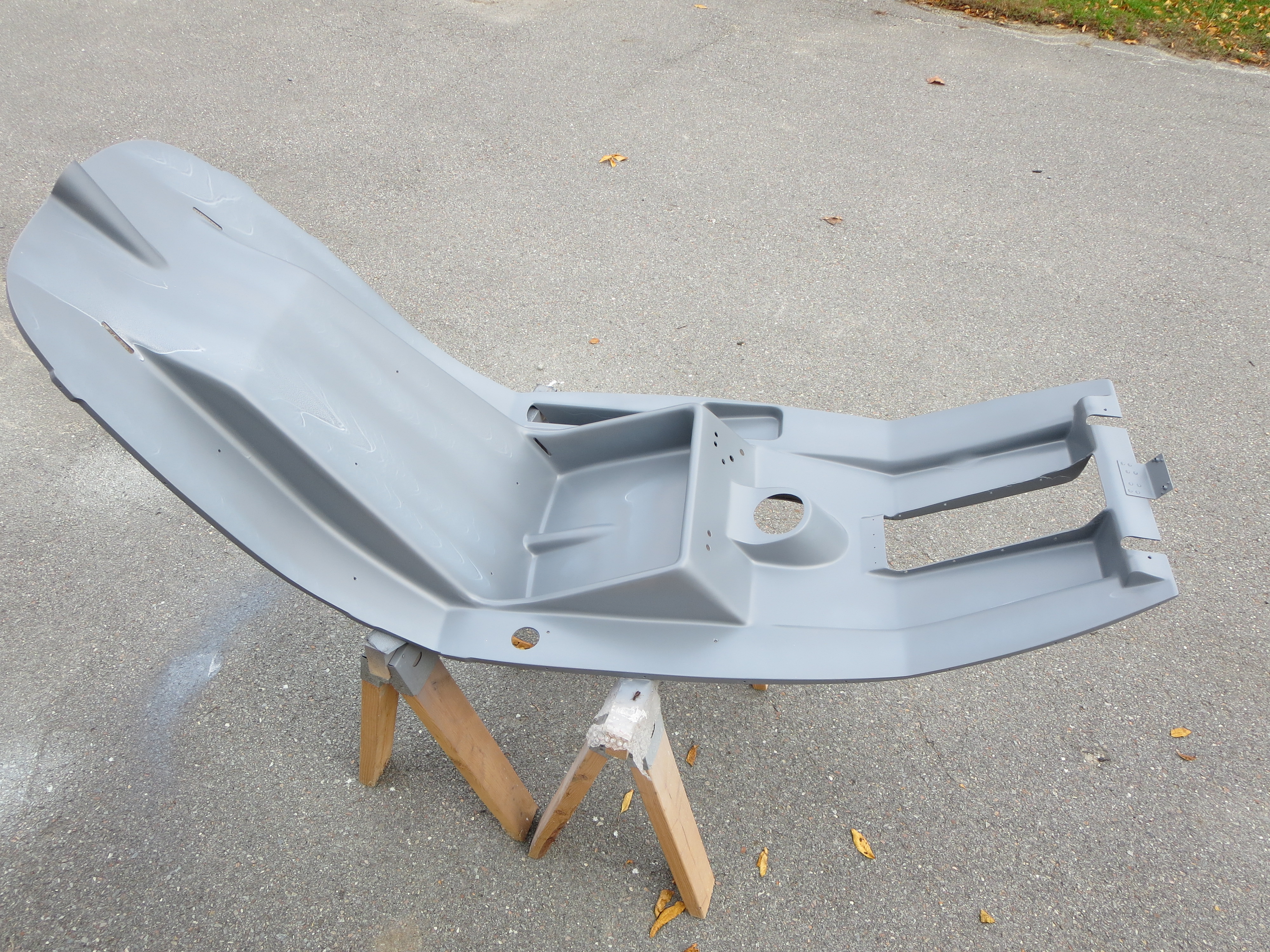
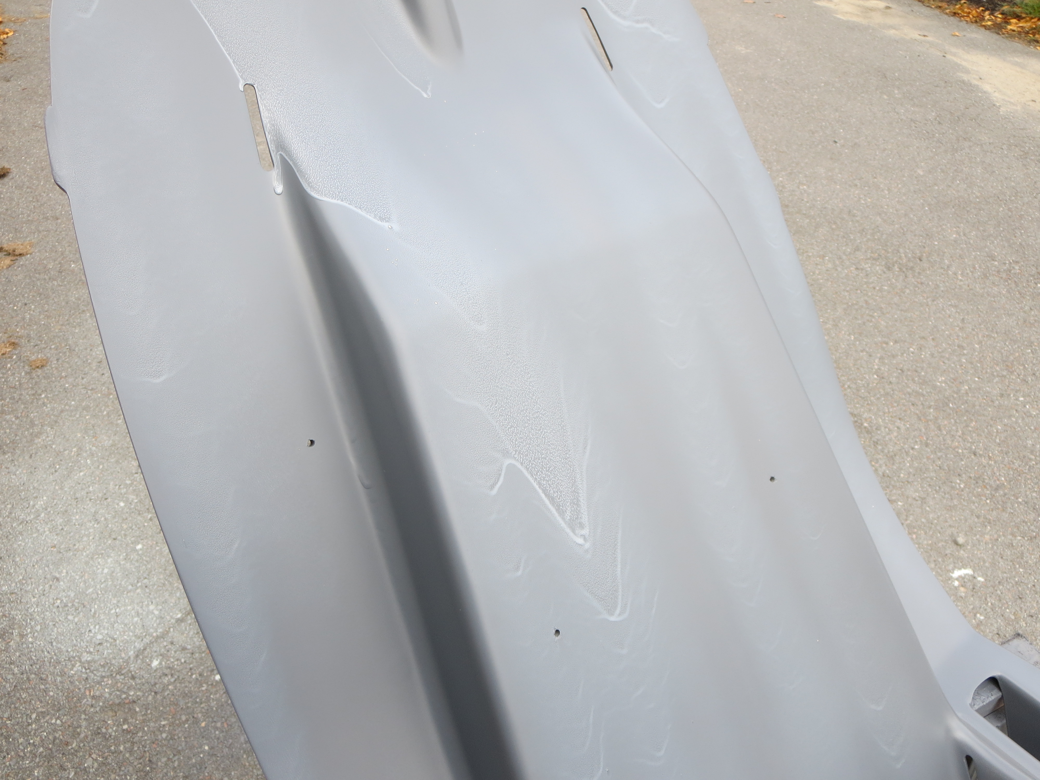
I had, at one point, considered lining the cabin interior with a fabric, but quickly dismissed it as weighty and labor intensive for limited gain in looks. To keep it simple and light, I lightly sanded it to remove the high-stranding fiberglass artifacts, then primed with the epoxy grey. I did not bother to fill the weave, or anything like that.
I wanted a finish that was light colored, but not reflective. The ideal solution was a stone finish spray paint. This is very similar to "spatter paint" that used to be popular as trunk paint for automobiles. I used Rustoleum "Simply Stone" granite finish. To me it looks nothing like granite, but for this application it looks pretty good.

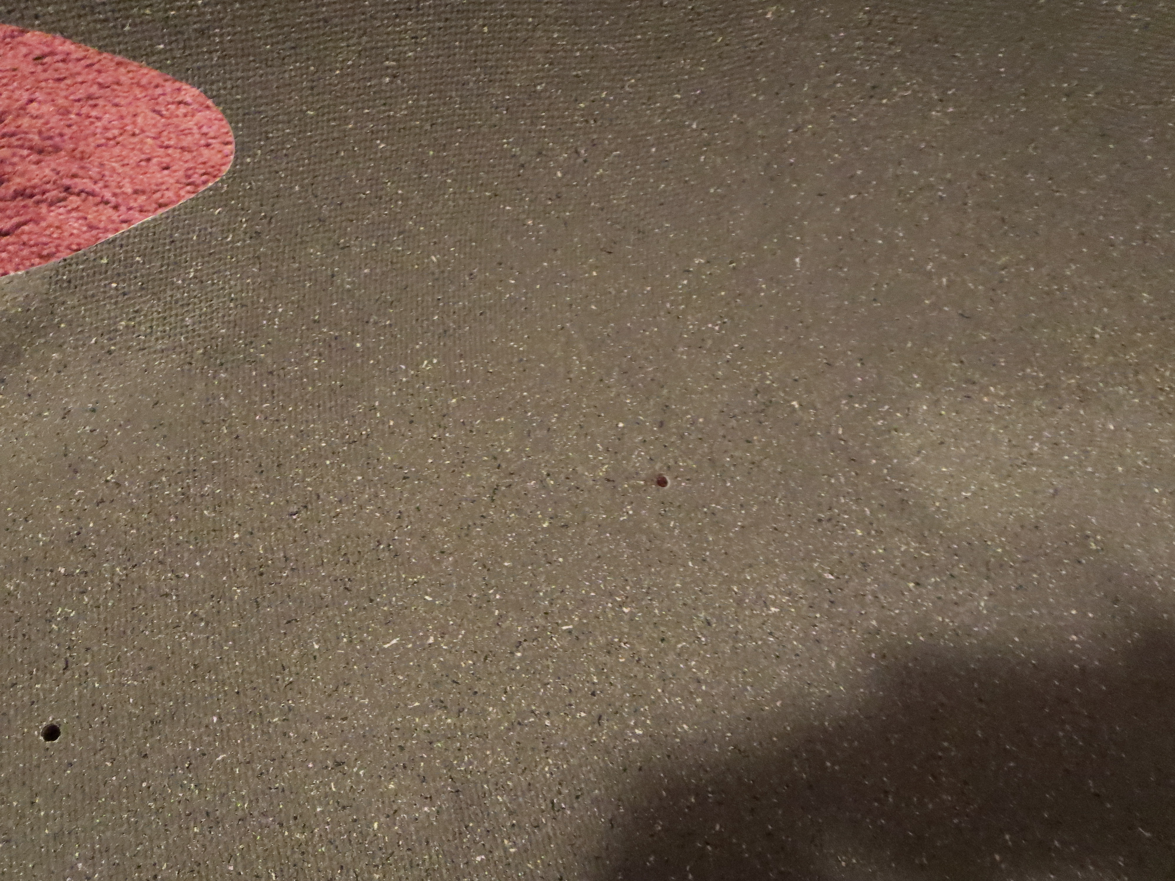
The best part is that it really masks the open weave of the rough interior of the fiberglass. I highly recommend this stuff as simple and easy for this application.
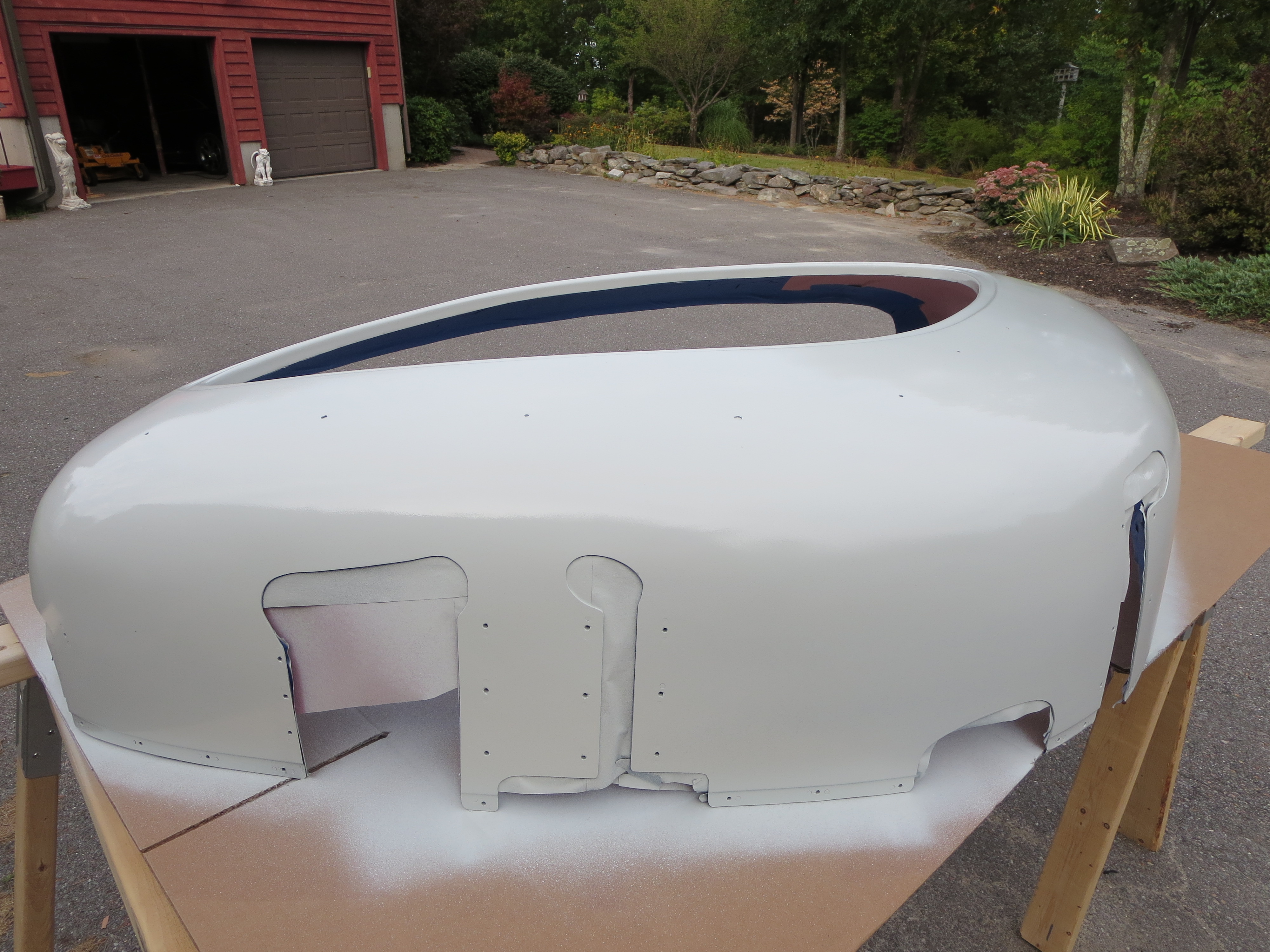
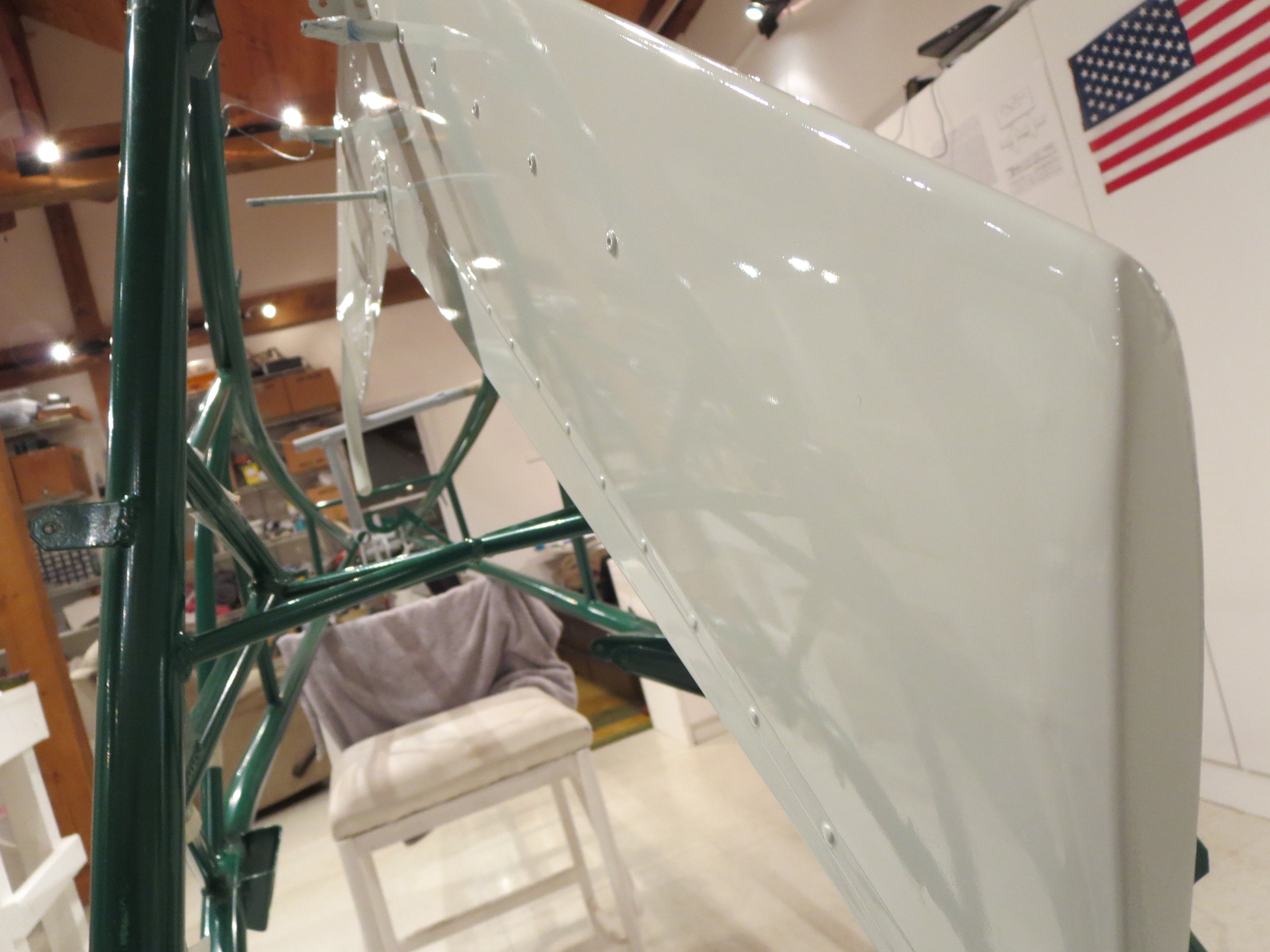
Cabin Exterior Painting
And thus begins the sad story of my cabin painting…
I have primed a bunch of stuff with only one real problem (see my SP priming entry), then I painted my fins and seat pan. The fins came out super-nice as did the seat pan. I was feeling like there were a bunch of pansies out there on the web, saying that painting was so hard and such an art form. If you read some folks descriptions it sounds like some god-like skills are needed. All of my things came out well enough that I was thinking there was not much to it. How wrong I was.
To make it easy for myself I had chosen a single-stage 2-part polyurethane paint for the cabin. The color is plain white, just to avoid any of the shading issues I read so much about.
When I painted the fins I was impressed with how nicely the urethane paint "flowed-out", and leveled itself, creating a glass smooth surface. So I jumped in to the cabin exterior using the skills and techniques I thought were developed at this point. The surfaces were primed, wet-sanded, masked and cleaned well. No problems. I used the same gun that I used for the fins.
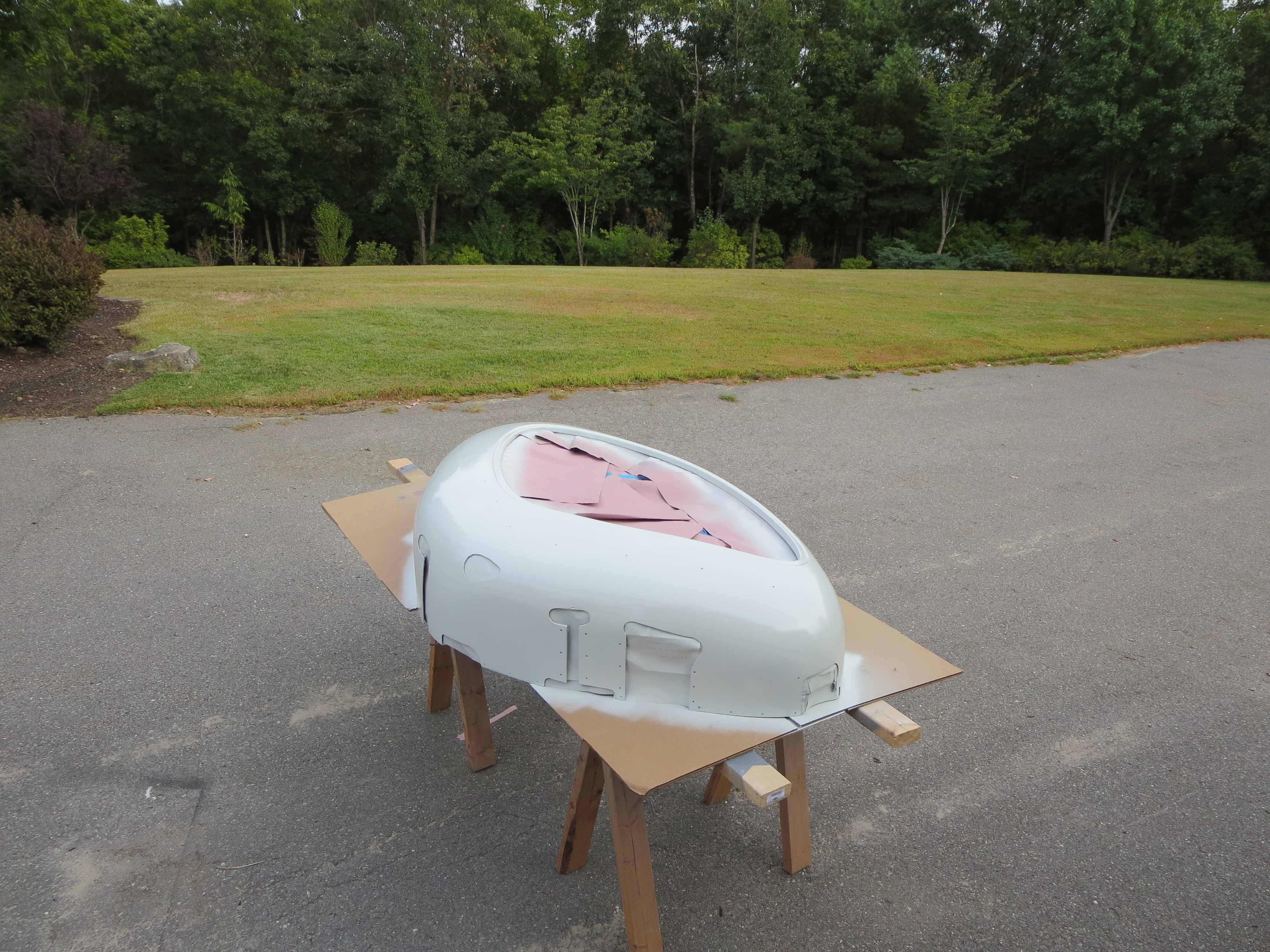
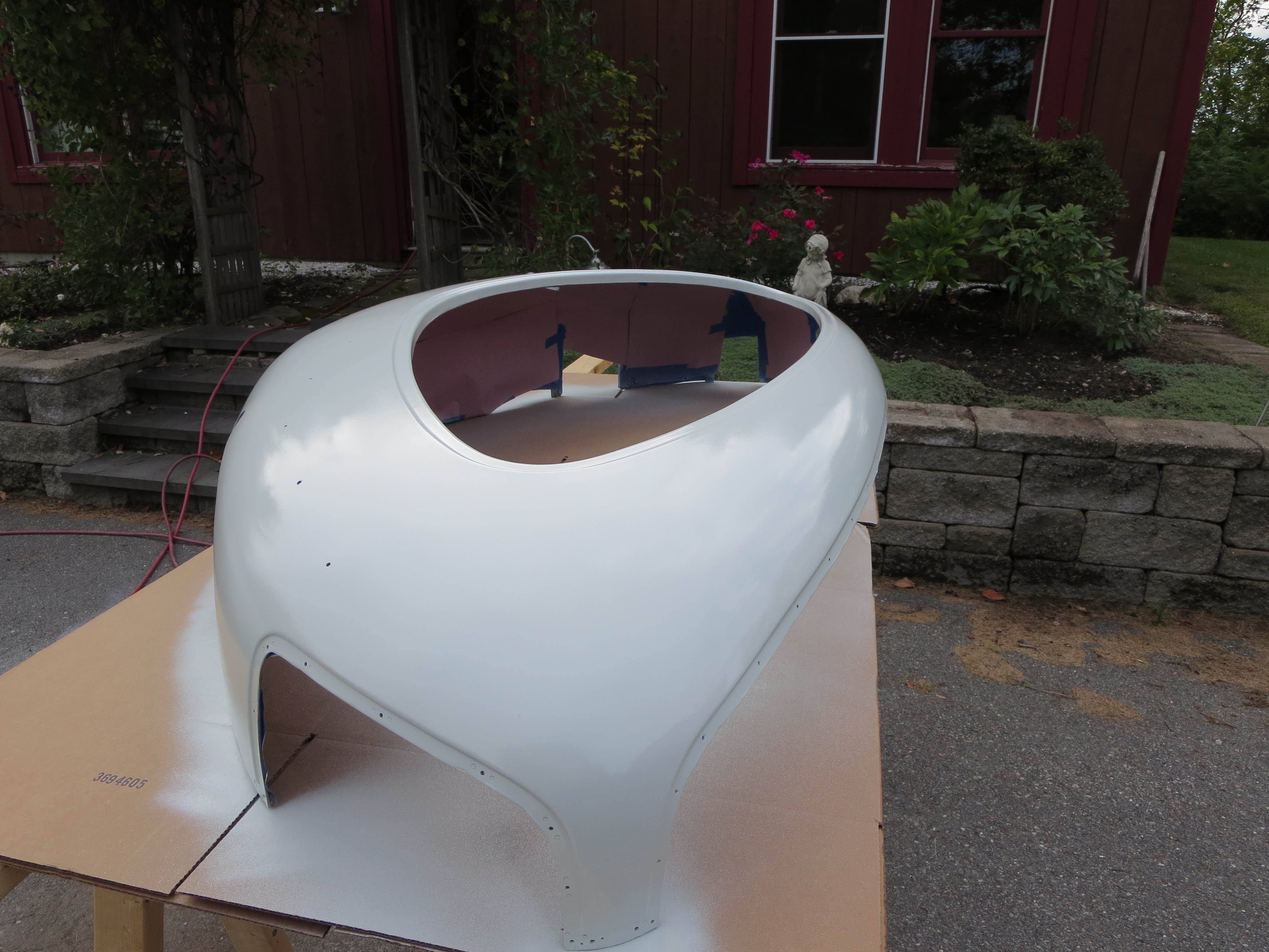
The first coat went on fairly light. It was mid-morning and the temps were in the 70's and the humidity was relatively low outside. There wasn't as much "flow-out" on the first coat as I would have liked, but it was a light first coat. I expected the second coat to flow out better.
Between coats there must have been something in the gun that I had missed during the previous cleaning that broke off and clogged one of the output holes on the nozzle. No problem, I had another of the exact same gun in the shop. I would just swap the paint, set the new gun exactly as I had the first and carry on. This was my mistake. I made a couple of test swipes on my practice piece that is always outside when I am painting. It was a little grainy, but basically OK - or so I thought. I figured it would flow out in a minute or two.
Coupled with that was the fact that is was later in the day, the sun was now out brightly, and the humidity was even lower than before. After I laid down the next coat (on both cabin half exteriors) I noticed that it was not flowing out as I had experienced in the past. OK. Not good. I increased the flow a tad to try to increase the quantity So it would flow better and "fill-in" the grain. What I learned later was that I should have lowered the pressure as what I was experiencing was dry-spray, not a flow problem. Too much air was effectively drying the paint on the way out of the gun causing a graininess. Nuts. Even though my second gun looked exactly the same and was the same model, the second gun was a newer gun and was very different internally (I learned later).
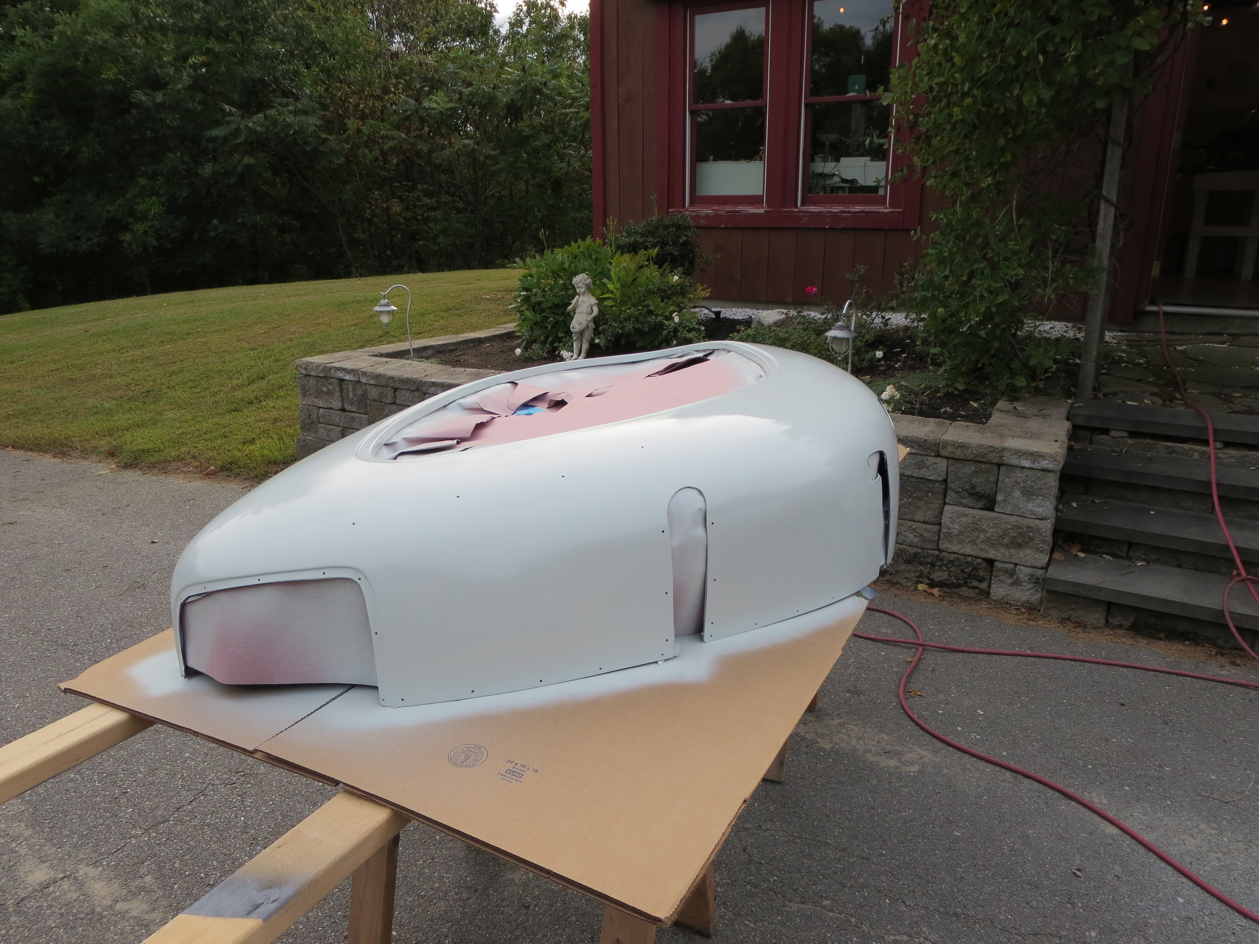
Decision time; Stop or continue? In that few seconds I decided to lay down as much paint as I had and sand it smooth later. It was either that, or stop, let it dry, sand it all off, reprime, and re-paint. Other factors at work were the fact that this was probably one of the last days I was going to get with a good temperature and warm enough outdoors to paint.
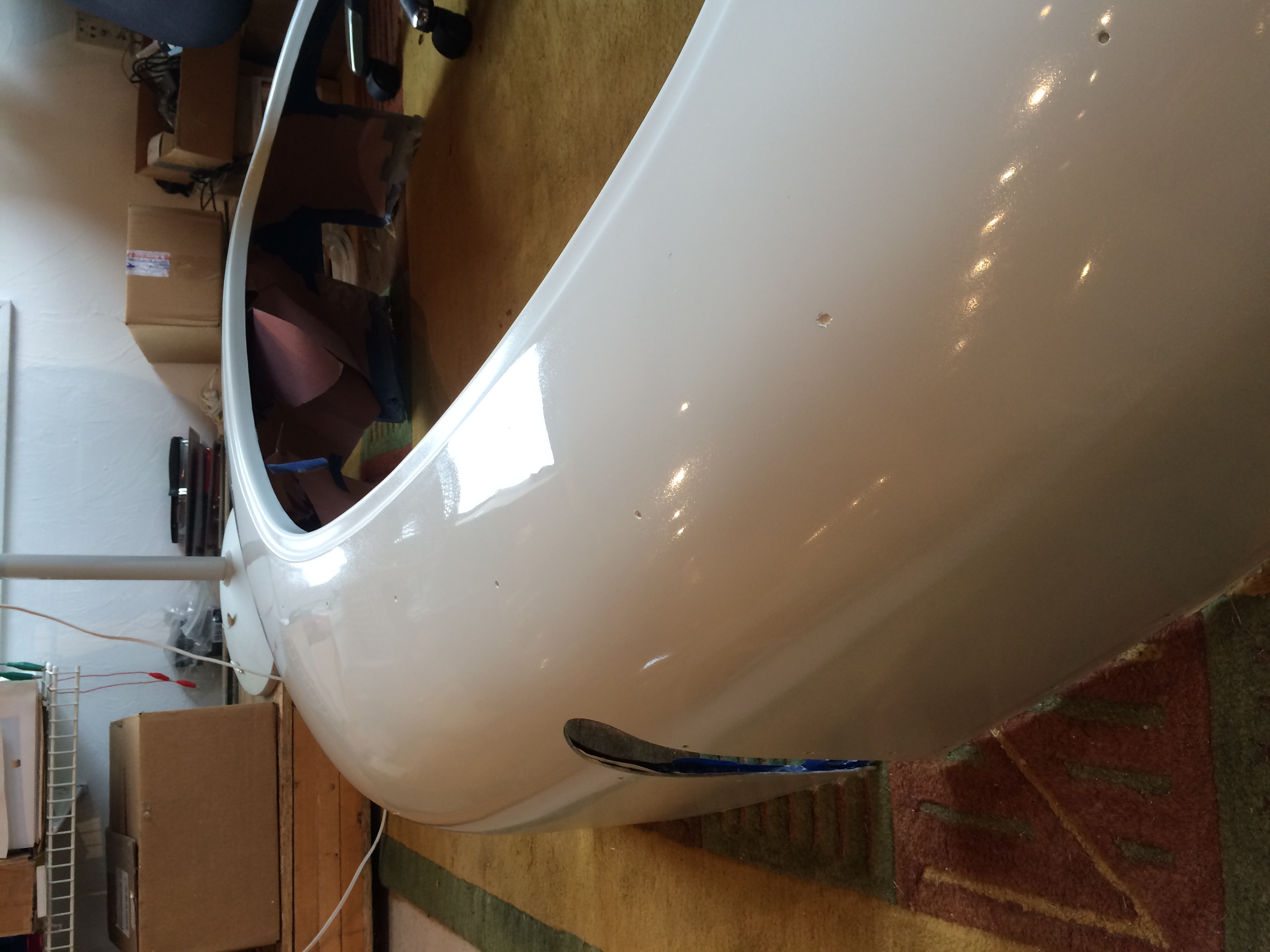
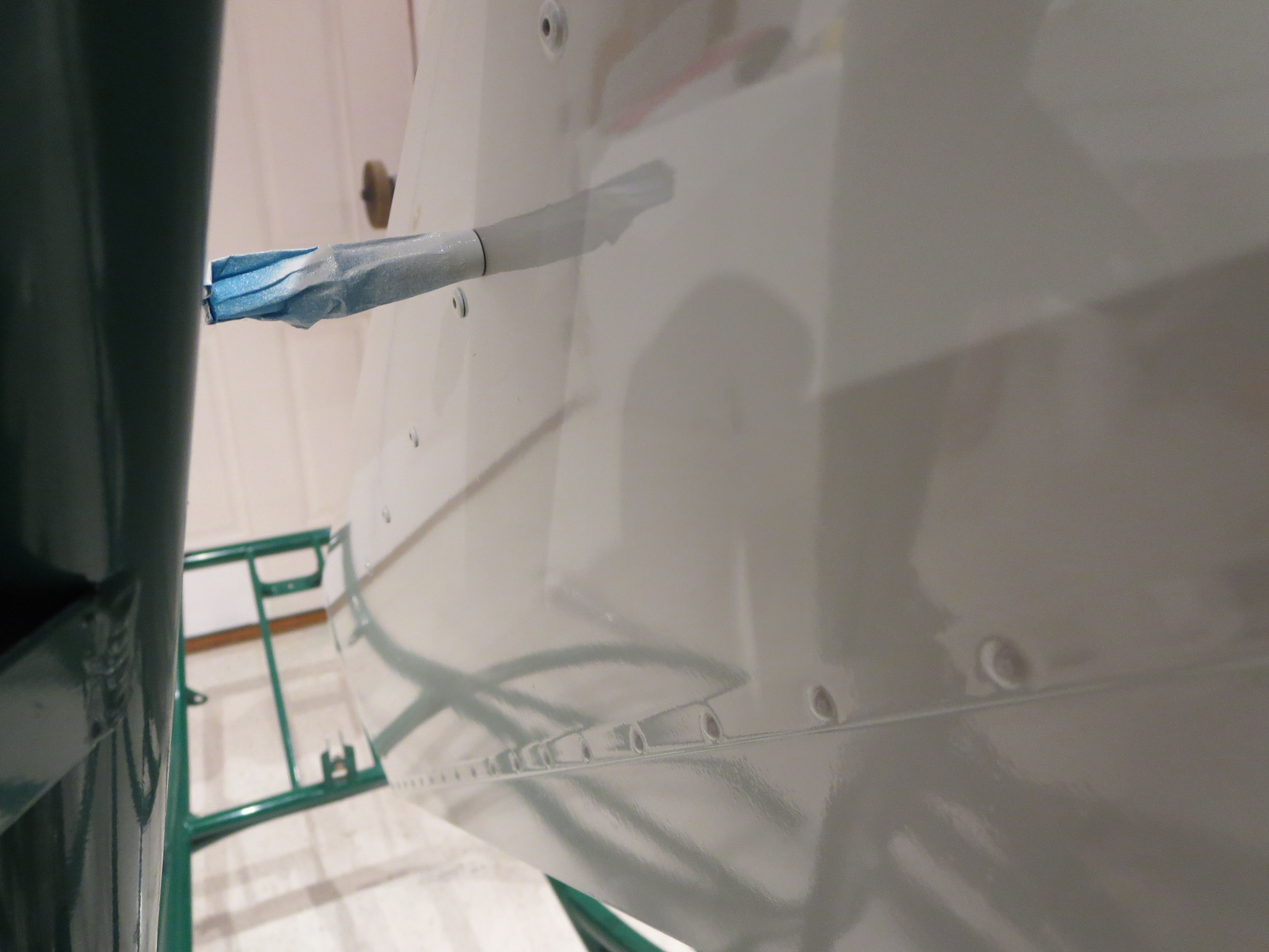
So there I was - I had two cabin halves with the surface texture of table salt. It really looked bad. Time to start sanding. I hoped that I had laid down enough paint so that I would not thin it too much.
The next two weeks of evenings were spent with a spray bottle of water, sandpaper and dual-action orbital polisher. Start with 500 grit (yes 500 grit for real), wet sand, then work to 800, 1000, 1200, 1500, and then 2000. Follow that with a multiple passes of the polisher with an aggressive cutting compound. Wipe it all off, look at it with a bright light and repeat, starting with the coarse grit on up. Repeat. Repeat. Repeat.
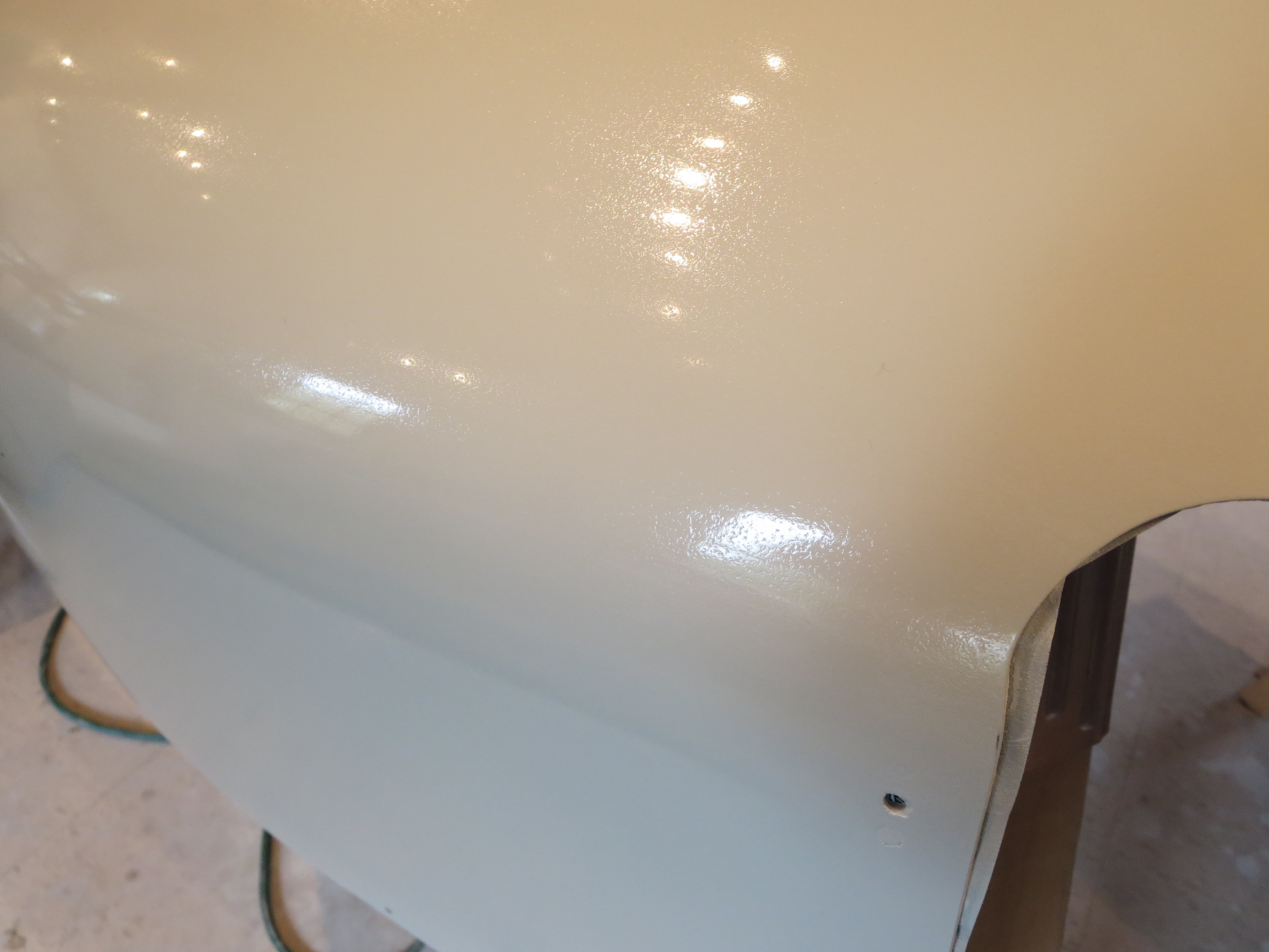
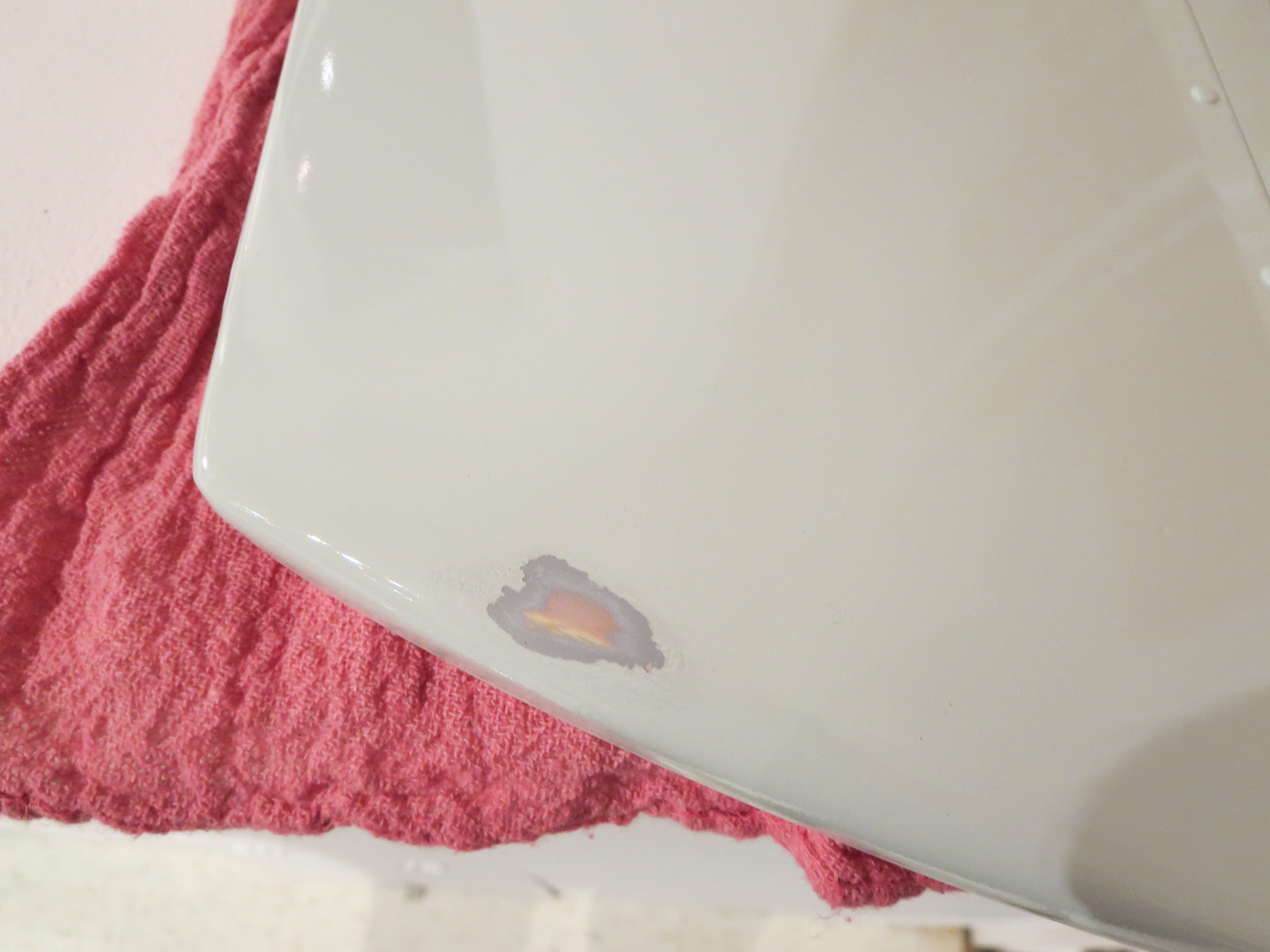
I learned an awful lot about how paint behaves. First or all, it is very possible to work with paint. If it was just some light orange peel, I am confident that I could have smoothed it out nicely, with labor, of course, but not too bad. The problem with my situation was depth. If you think of the surface in profile as a jagged series of little sawtooth mountains, it is easy to sand off the "peaks". However, once you have created "plateaus", you have a much larger surface area, the ever growing plateaus, to sand to work in to the "valleys". Initial progress is fast and noticeable, then it slows way down.
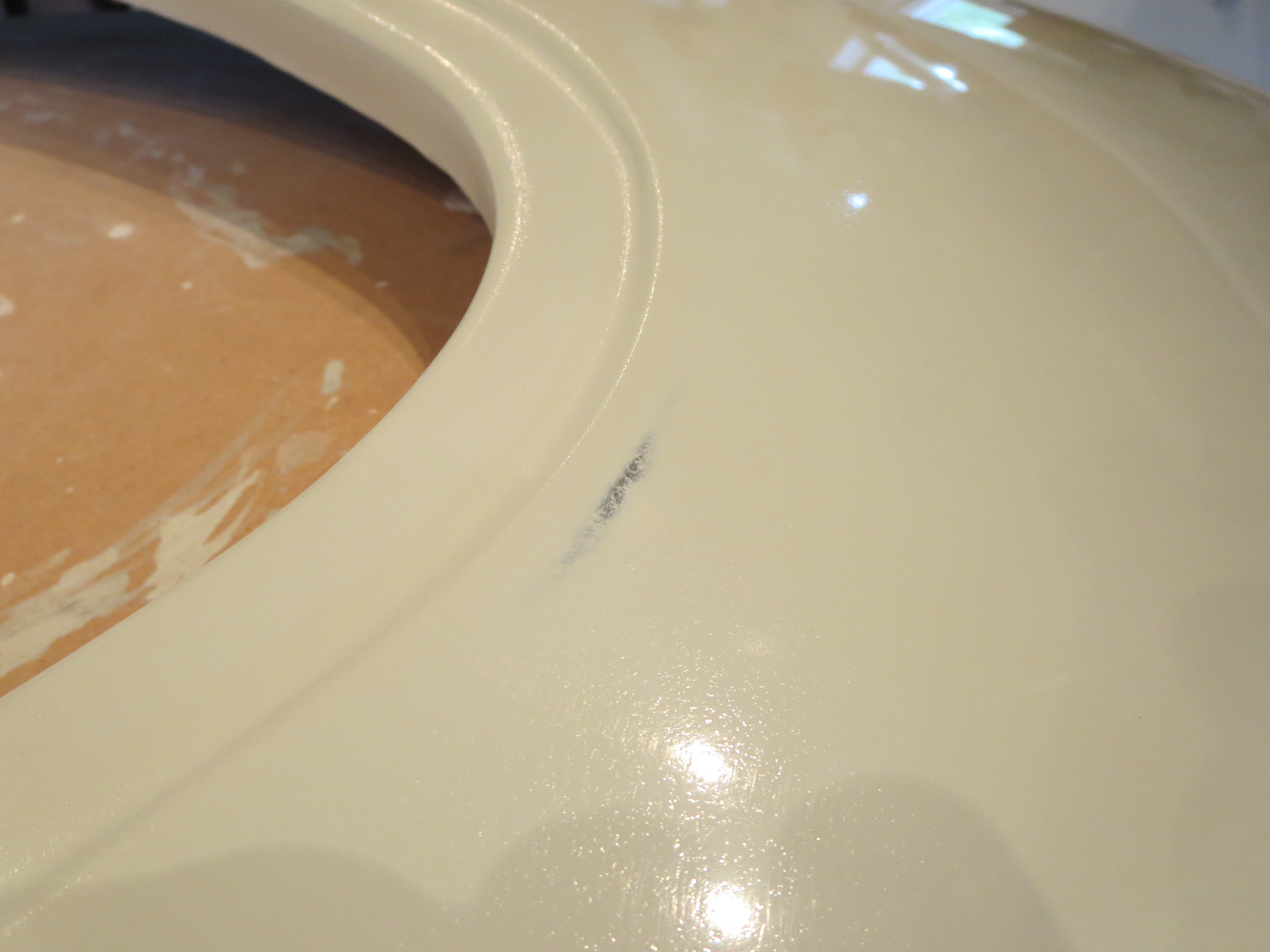
Coupled with that is that once you get close to the bottom of the valleys, the paint is getting very, very thin. There are couple of spots that thinned through. I am pretty sure that someday I will repaint the cabin, but I am not looking forward to it.
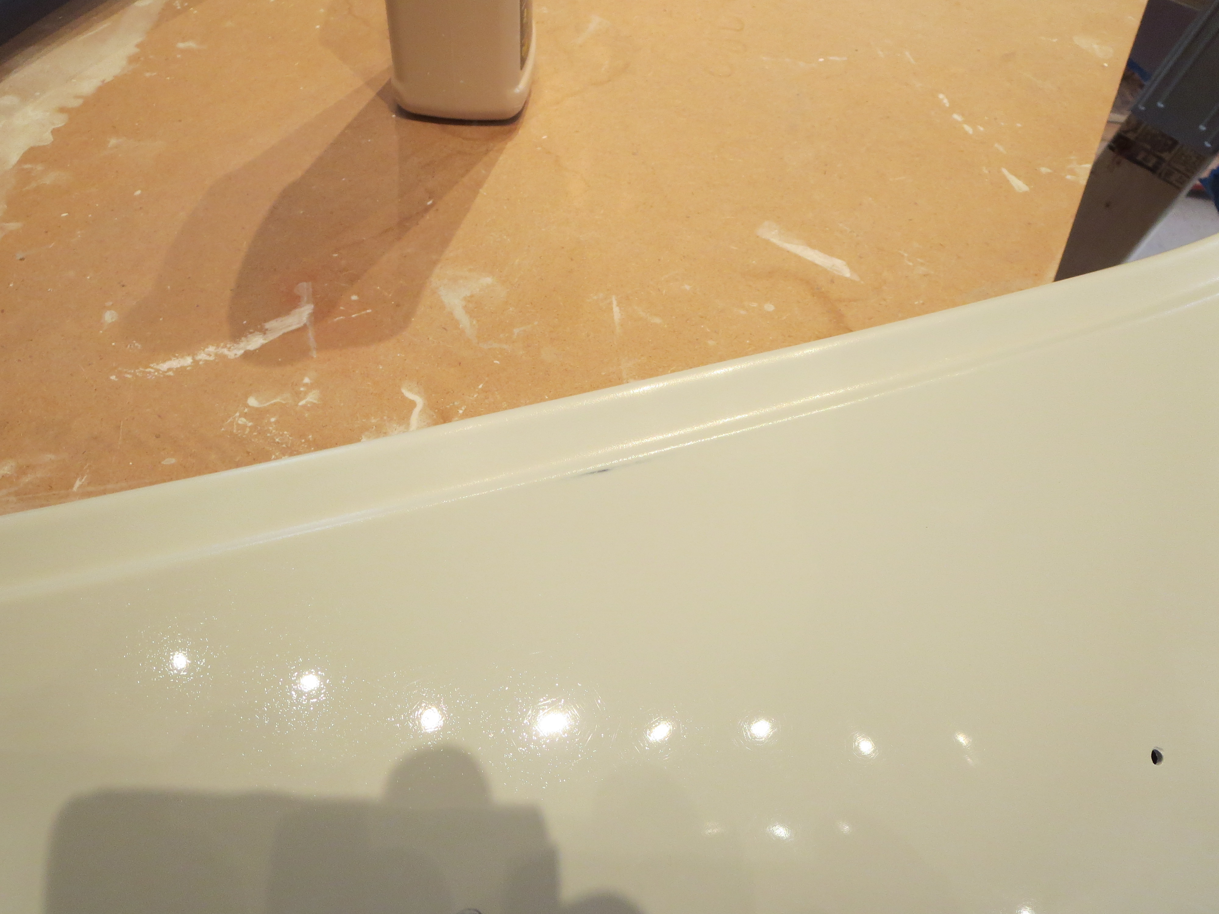
After all that, I got it to the 10-foot stage, From 10 feet away it looks OK. Closer and you start to notice the problems. I thinned it too much in 4 places. The lip around the door was impossible to smooth. I am at the point where I could spend 3 or 4 times longer than I have and it might improve, but it will never be perfect. I have decided to call the effort, continue on, and if it really bothers me down the line I will repaint the bird when it is down some winter. This is a learning experience. My next helicopter will be perfect.
Final Pan and Pod Painting
This has been an incredibly busy summer. Unfortunately little of it has had to do with helicopter building; trips to Asia, Europe, India and Mexico for work, and buying a house in Virginia have consumed all of my time and energy.
When I have had time to allocate to the helicopter, I wanted to get some of the cabin pieces completed so that over the coming winter things could be mounted permanently.
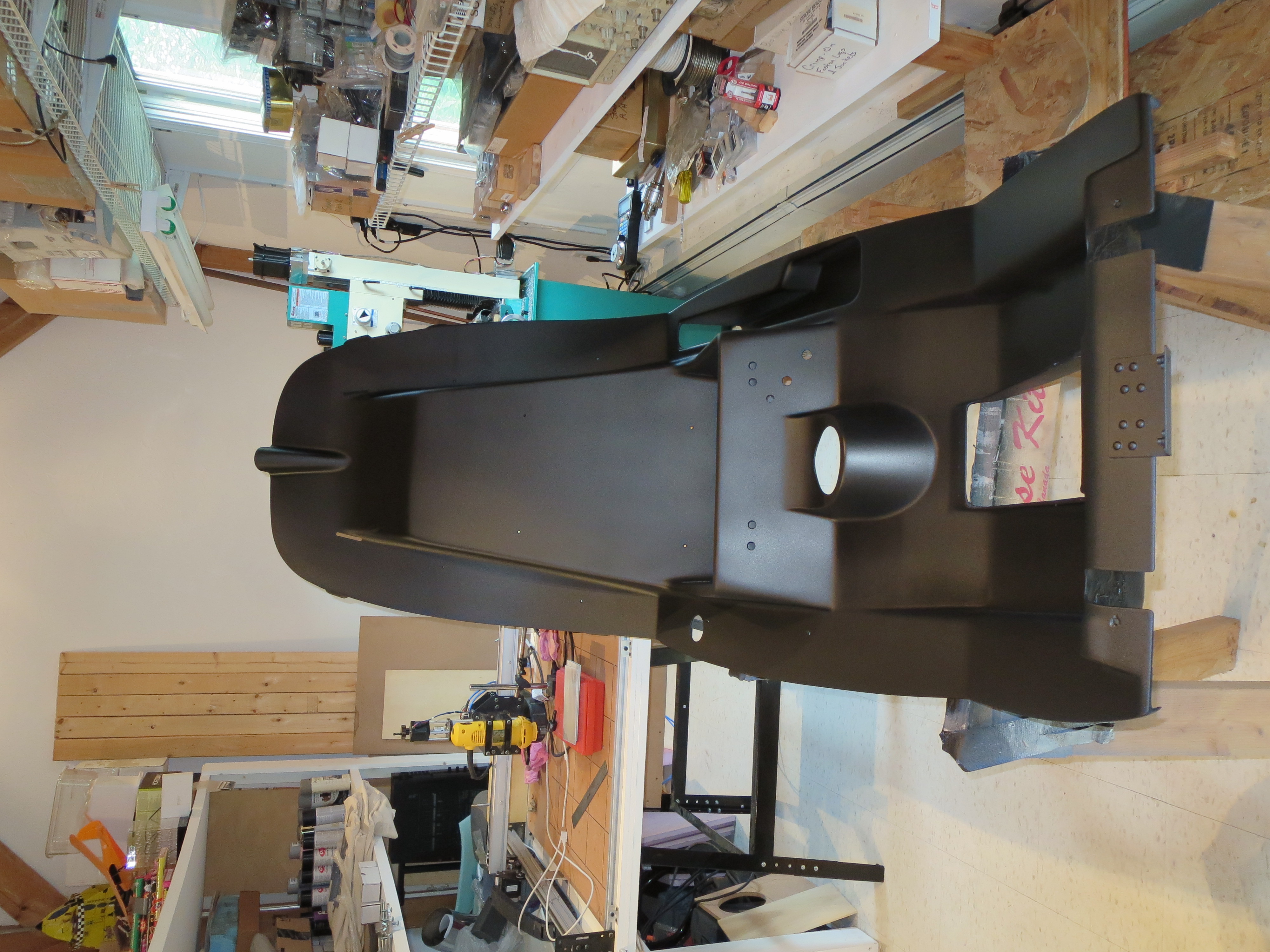
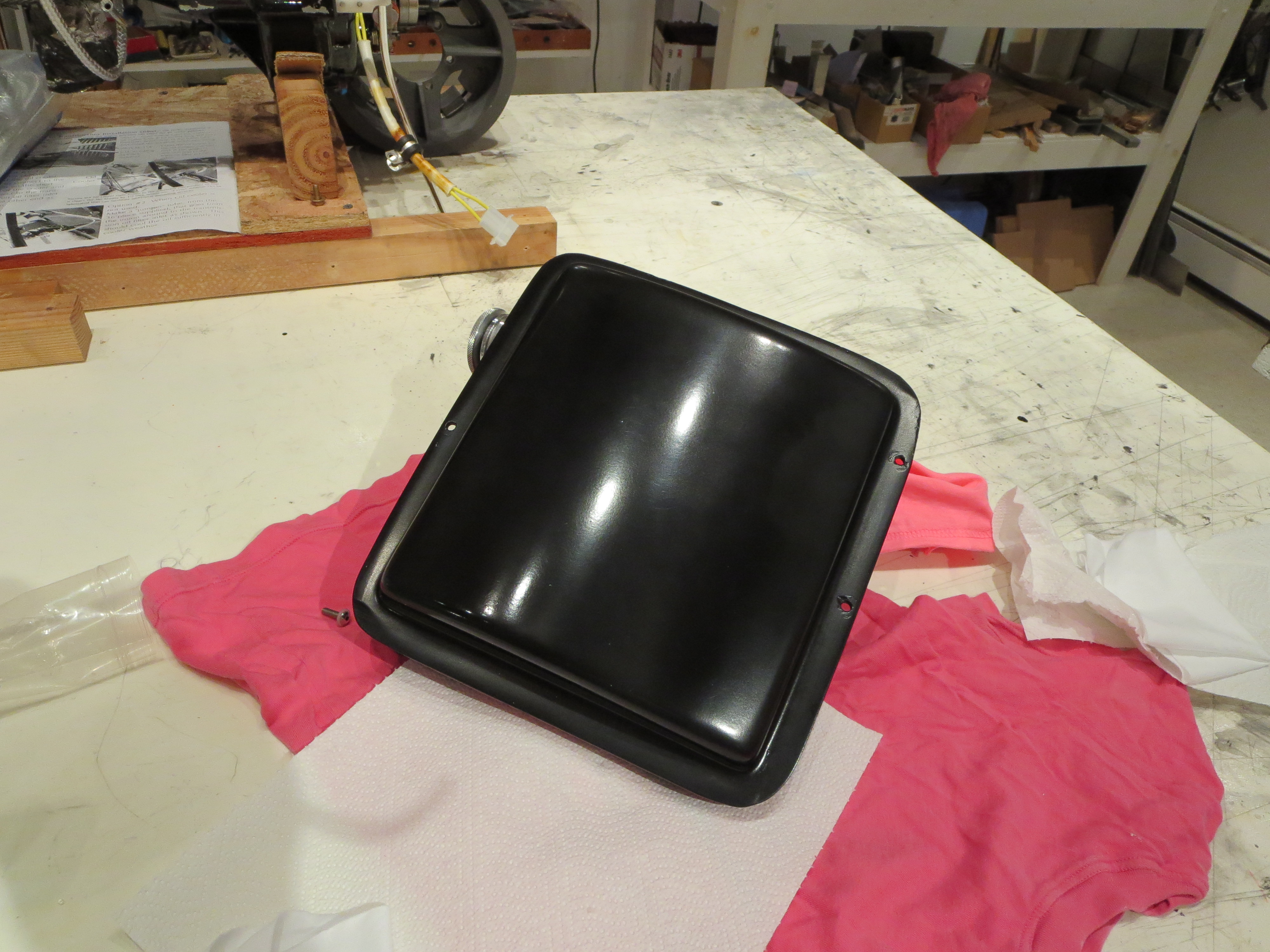
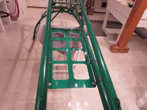
I started the final painting with the seat pan. The finish selected is satin "Rat Rod Black". This is a flat black with a little bit of texture. The intention is that there be no unwanted reflections on the canopy.
After my priming problems I was a little wary, but the Rat Rod Black went on beautifully. I have found that textured paints are forgiving and relatively easy to apply.
I a quite satisfied with the results on the pan. The pod and panels were painted with the same stuff and they also came out nicely and as expected.
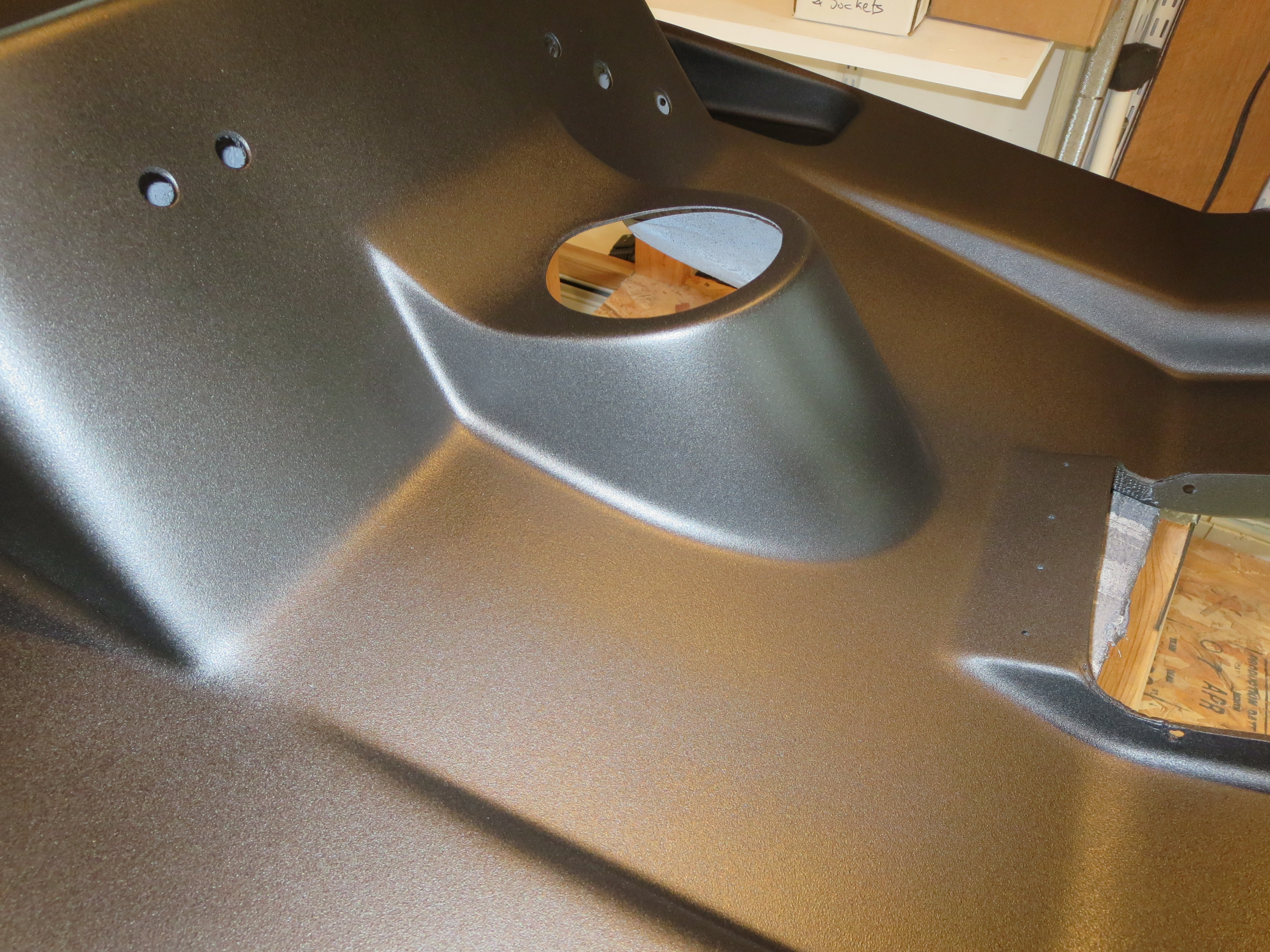
Doesn't that look nice? Very satisfying. The pod was a little more challenging because of the curves and undercuts, but it too came out well. Overall, I am very satisfied with these pieces.
CNC Mill
I did not want to spend a lifetime converting the machine, nor did I want to spend more than about $3500. This machine is substantial enough to cut up to maybe 1/2" aluminum. Parts and plans are readily available. I procured all the bits and pieces, and budgeted 3 weekends for the conversion. It took about three times that long as there is a lot of fiddling to get things dialed in perfectly.
The conversion deserves its own page, which can be found here: CNC_MILL.
CNC Routed Parts
Fundamentally it lacks the stiffness for super-high accuracy or extremely clean cuts. It is belt driven and belts stretch. If you grab the carriage and wiggle it, you can move it back and forth maybe 10-15 mils. I have braced the metal frame, but fundamentally it is limited by that design compromise.
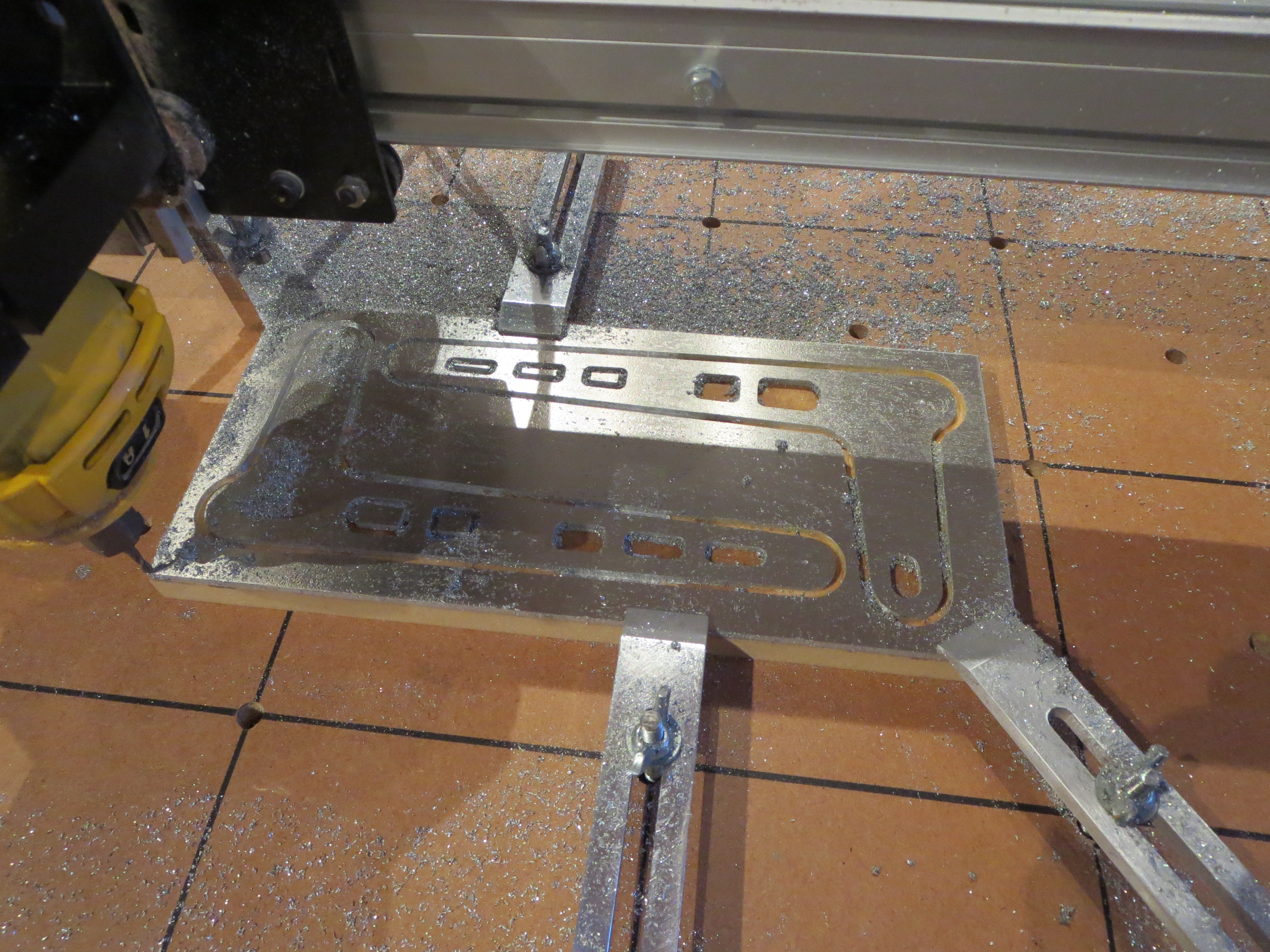
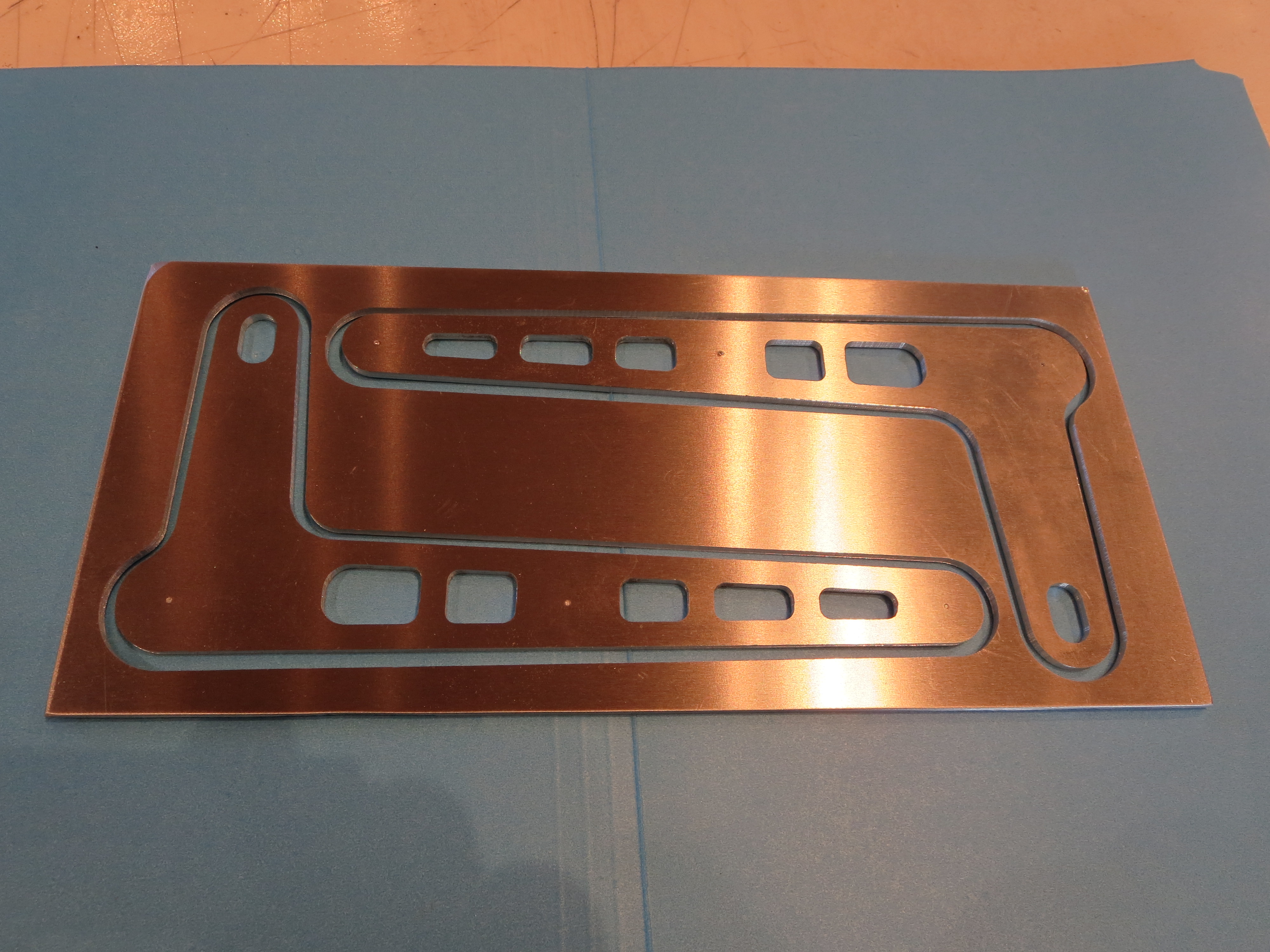
Still, for some sorts of things it is fine. I have just cut a new set of tail rotor control scissors. They are cut just as accurately as the hand cut ones I did earlier. The two pieces are nearly an exact match. The holes are drilled on the drill press as routing those holes would be insufficient accuracy. The routed slots for the steel bushings ARE at least as accurate as the hand cut ones.
I am satisfied with the results. Perhaps I will later try a new TR walking beam for pedal attach, The pieces I can fabricate are certainly straight, and light.
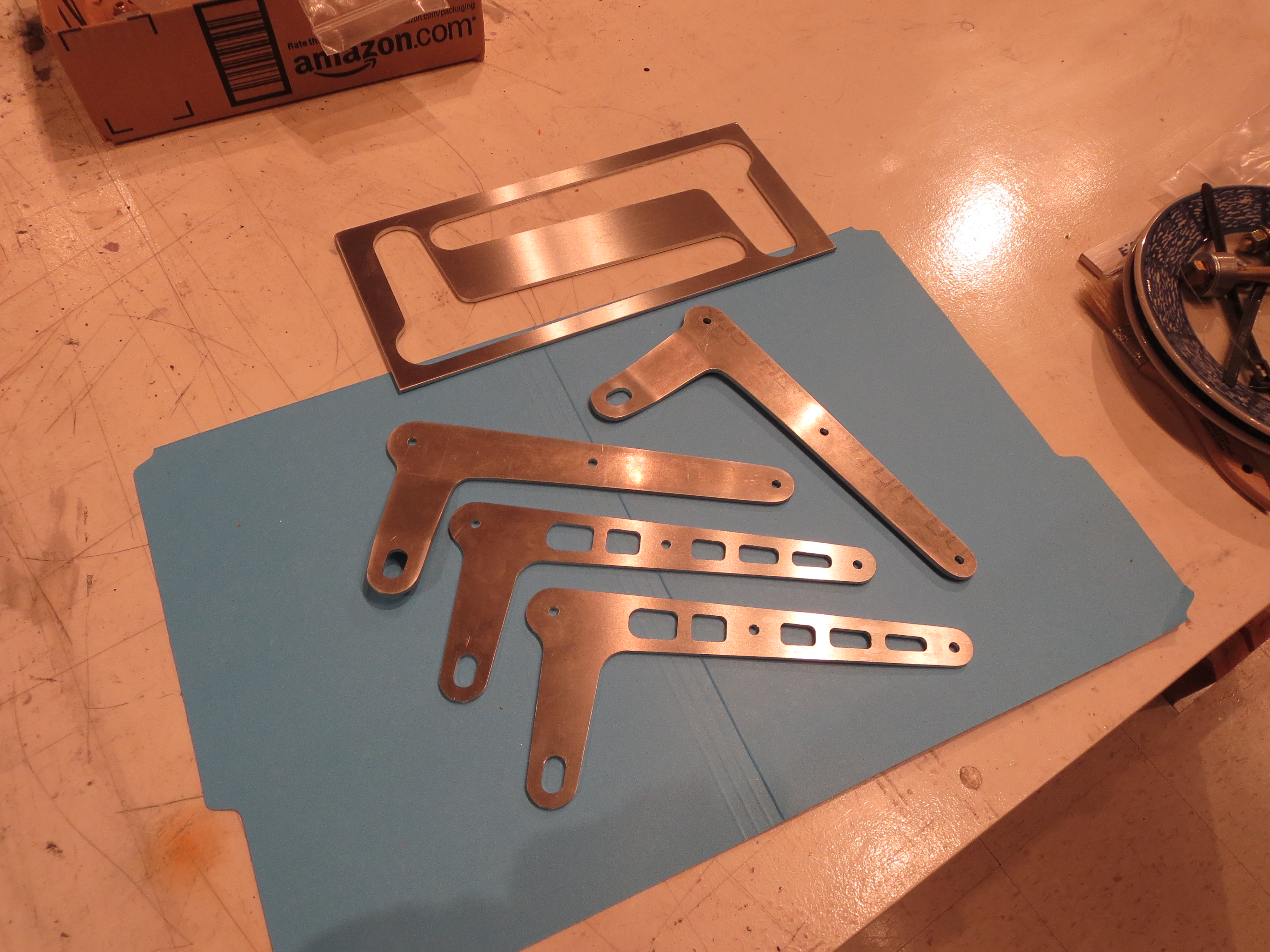
Old and new compared.
Rotor Tach
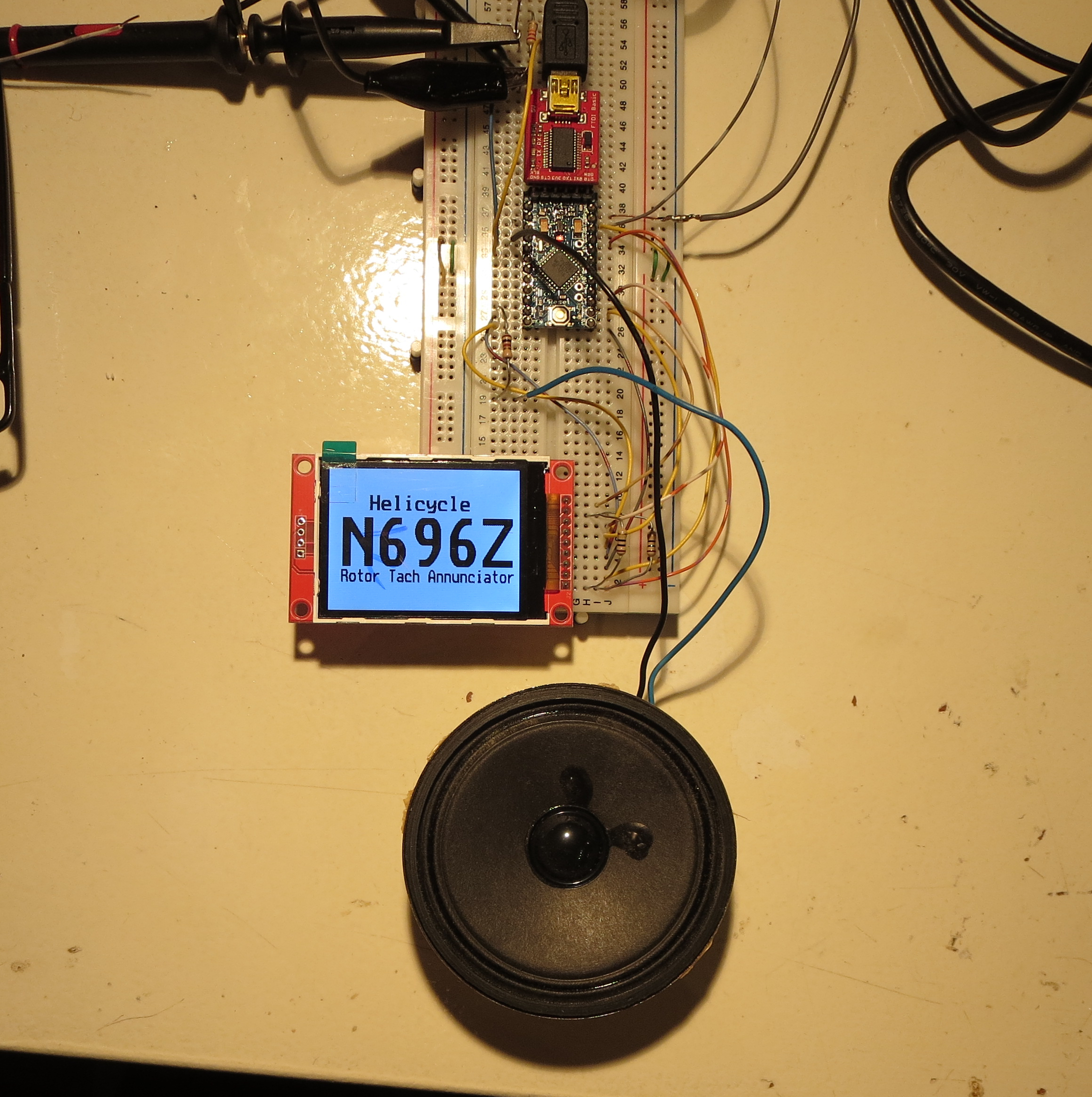
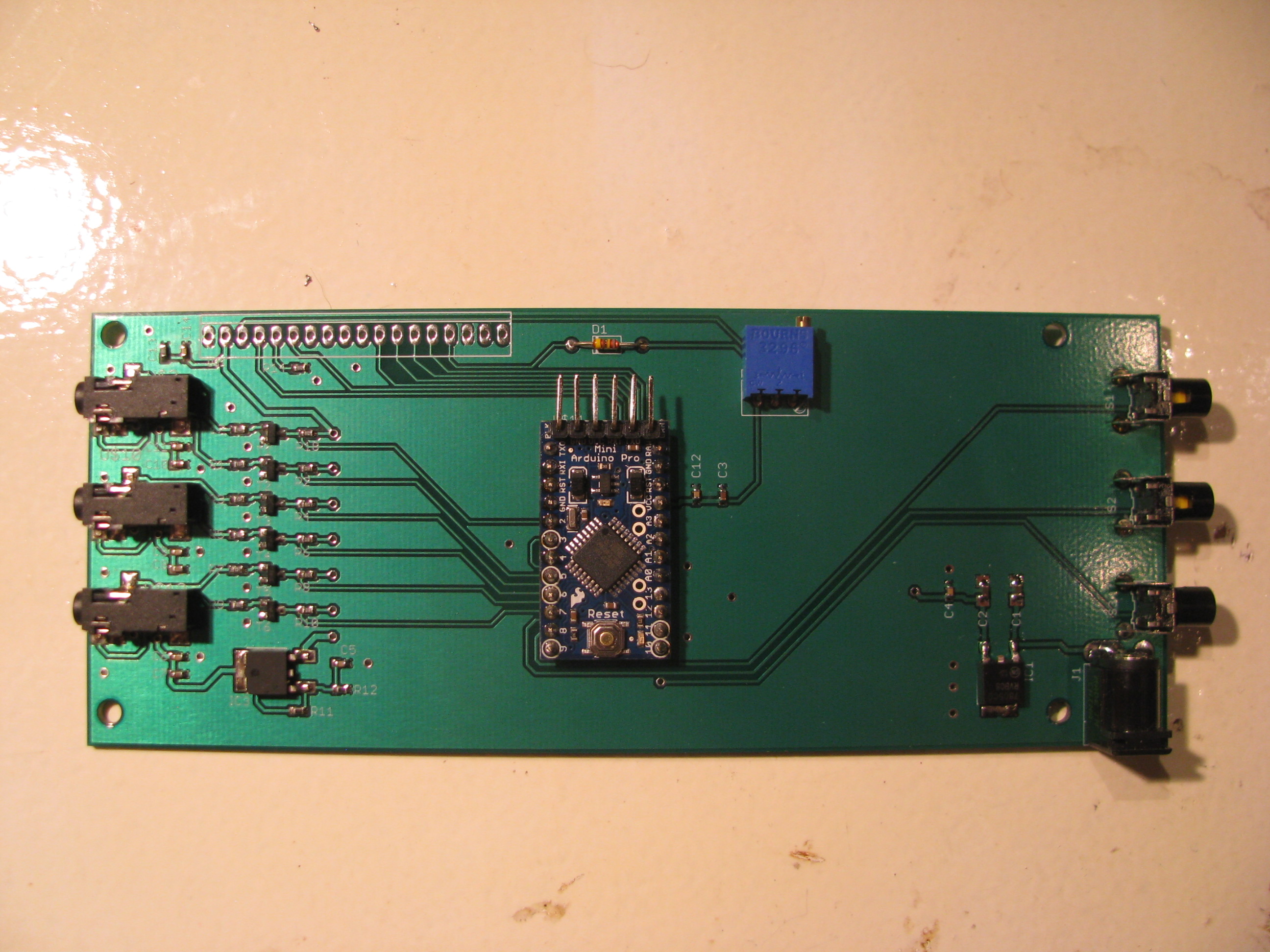
I built this little display item. It is based on a 2" display from eBay and an Arduino processor. There will need to be some conditioning to amplify the incoming signal and to make sure the analog tach is not affected. On the bench I use an audio tone generator to mimic the signal form the sensor.
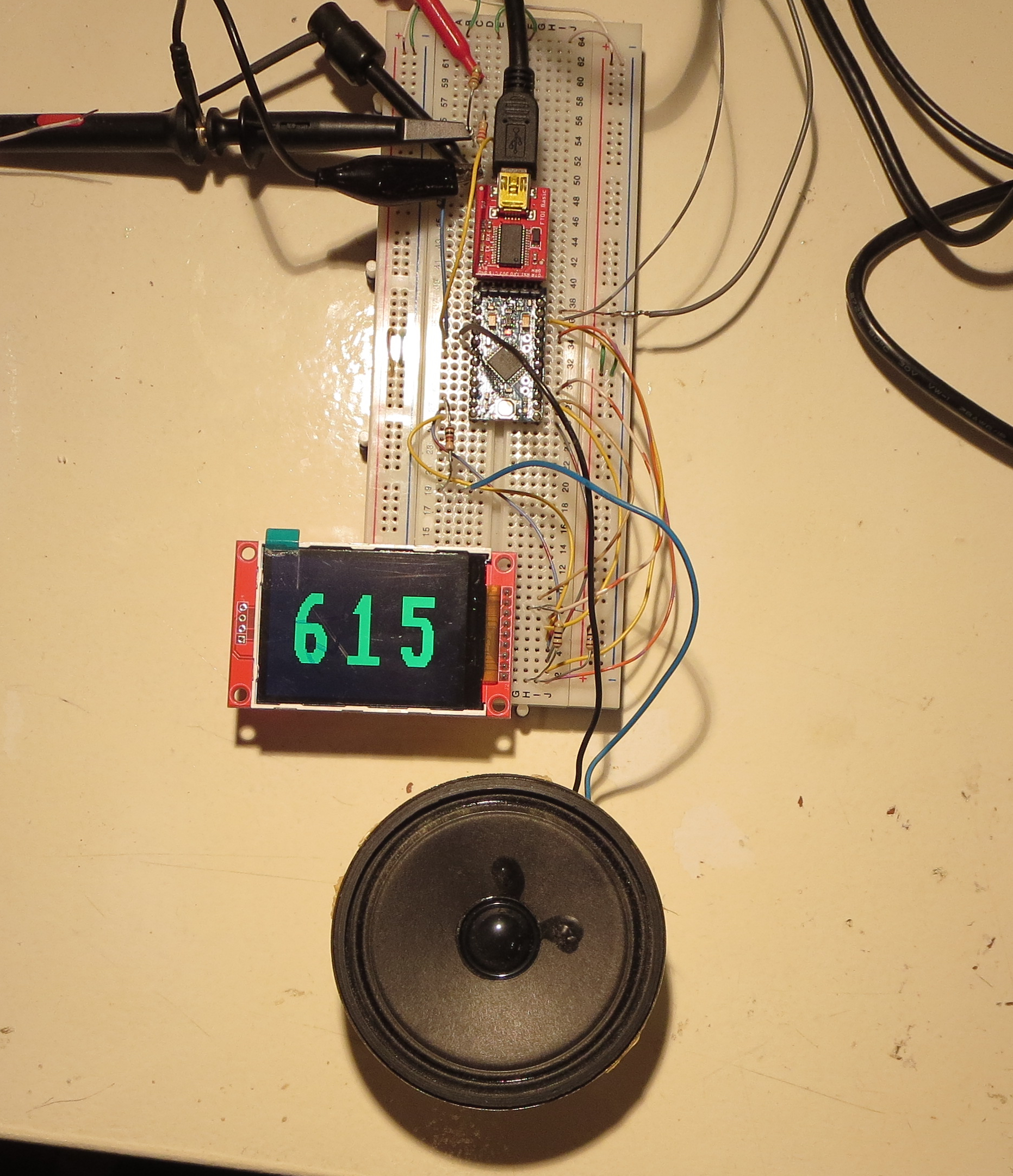
If the rotor is in the range of 610 to 620 the RPM is displayed in green.

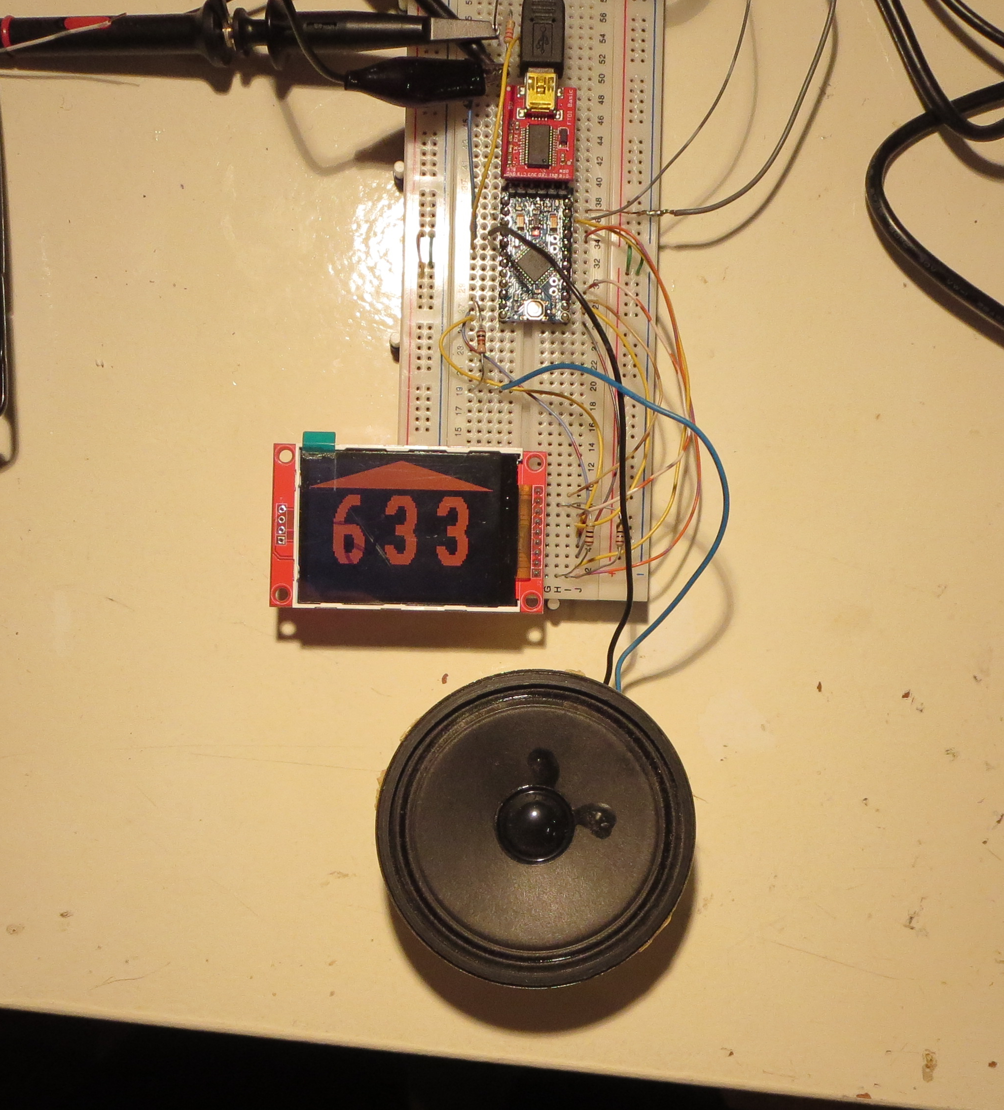
When in the range of 605 to 610 the RPM is yellow with a downward pointing arrow and a tone. Between 620 and 625 the RPM is also yellow with a higher pitched tone. Above 625 the reading is red with a red up arrow and a higher pulsing tone. Similarly below 605 it is also red with a red down arrow and a pulsing low pitch tone.
This is designed to be easy and very quick to read with an attention getting audio tone mixing in to the headset feed. I plan on mounting it on the top of the pod as it is critical to interpret this quickly during autorotations. In the final incarnation this will be packaged well and be brighter. The display shown here is a tired old one I have beaten and abused and use for development where I may actually damage it.
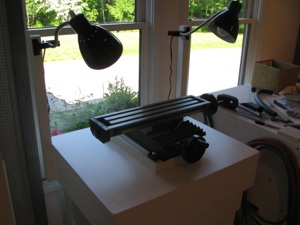
Jack Table
The engine went on the floor and I modified the cradle so I could just hoist it straight up and out.
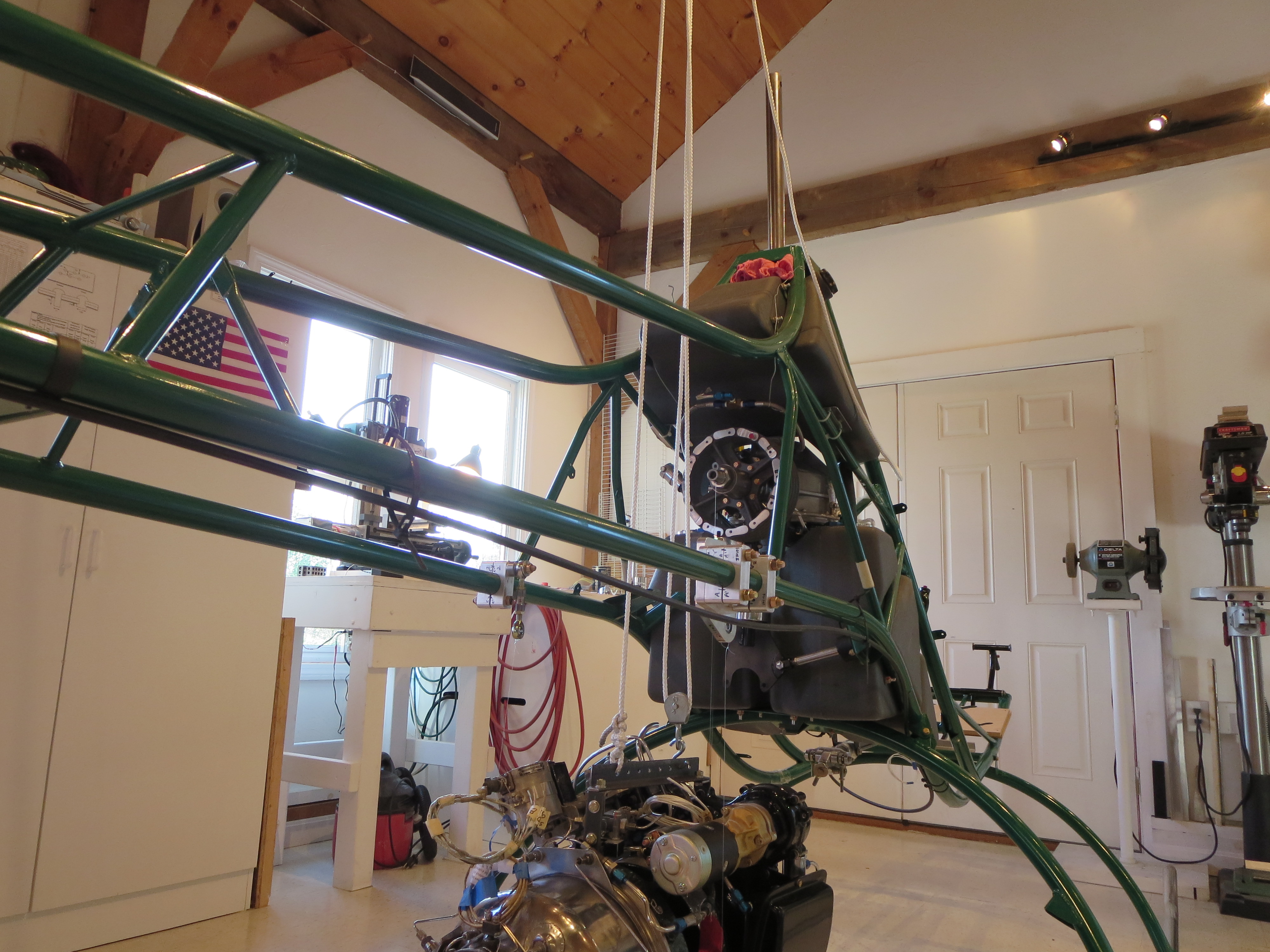
Then I tried lifting the engine with my pulley system. Two problems; 1) The rope was quite stretchy. I can't imagine trying to position the engine precisely with this system., and 2) Seeing the engine dangling from a few thin strands was too nerve-wracking. That's 10-15K worth of turbine swinging on some home-depot rope.
It probably would have been fine, but between the swinging and the tough precision thing I knew I wanted to do something different.
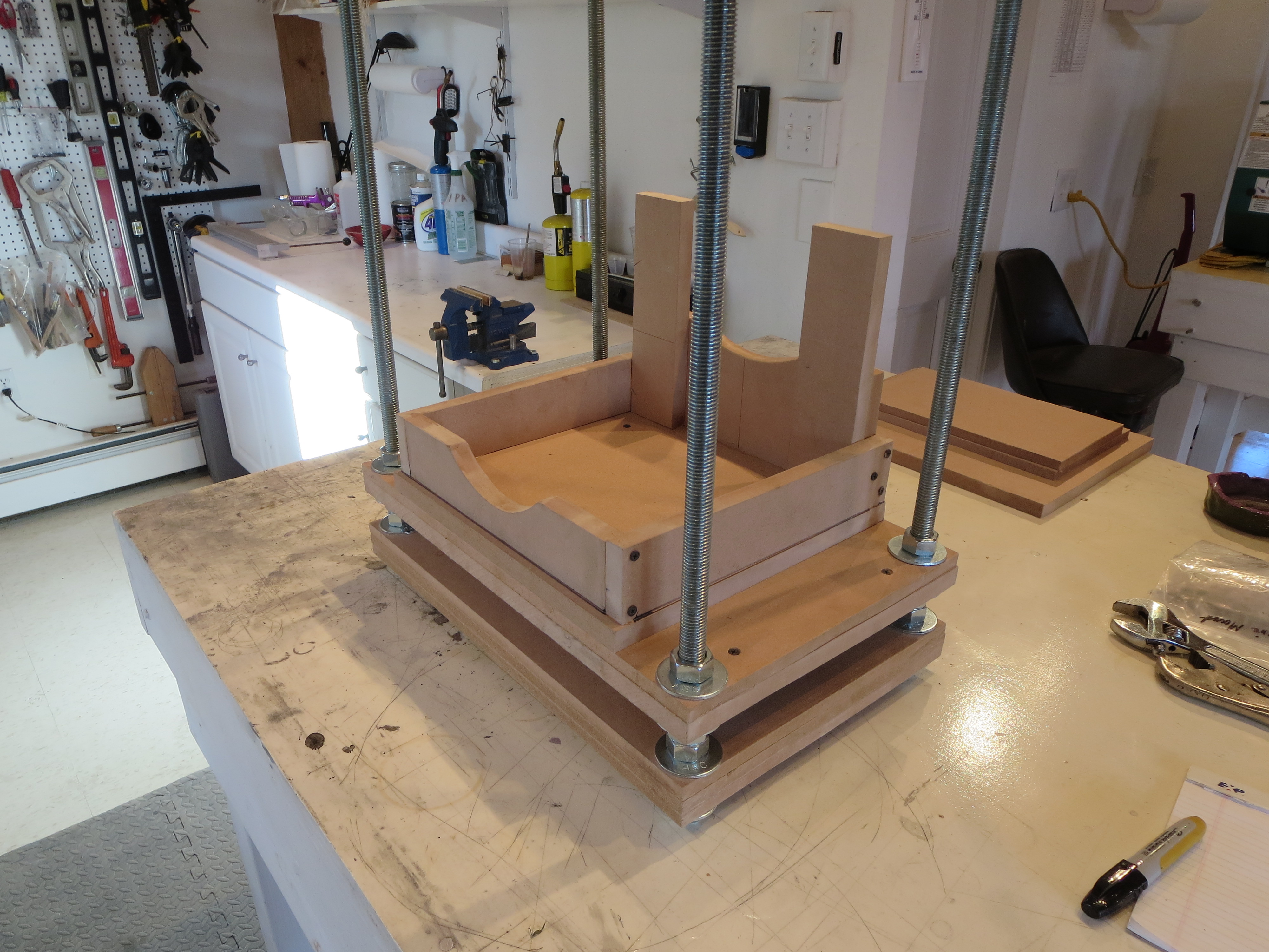
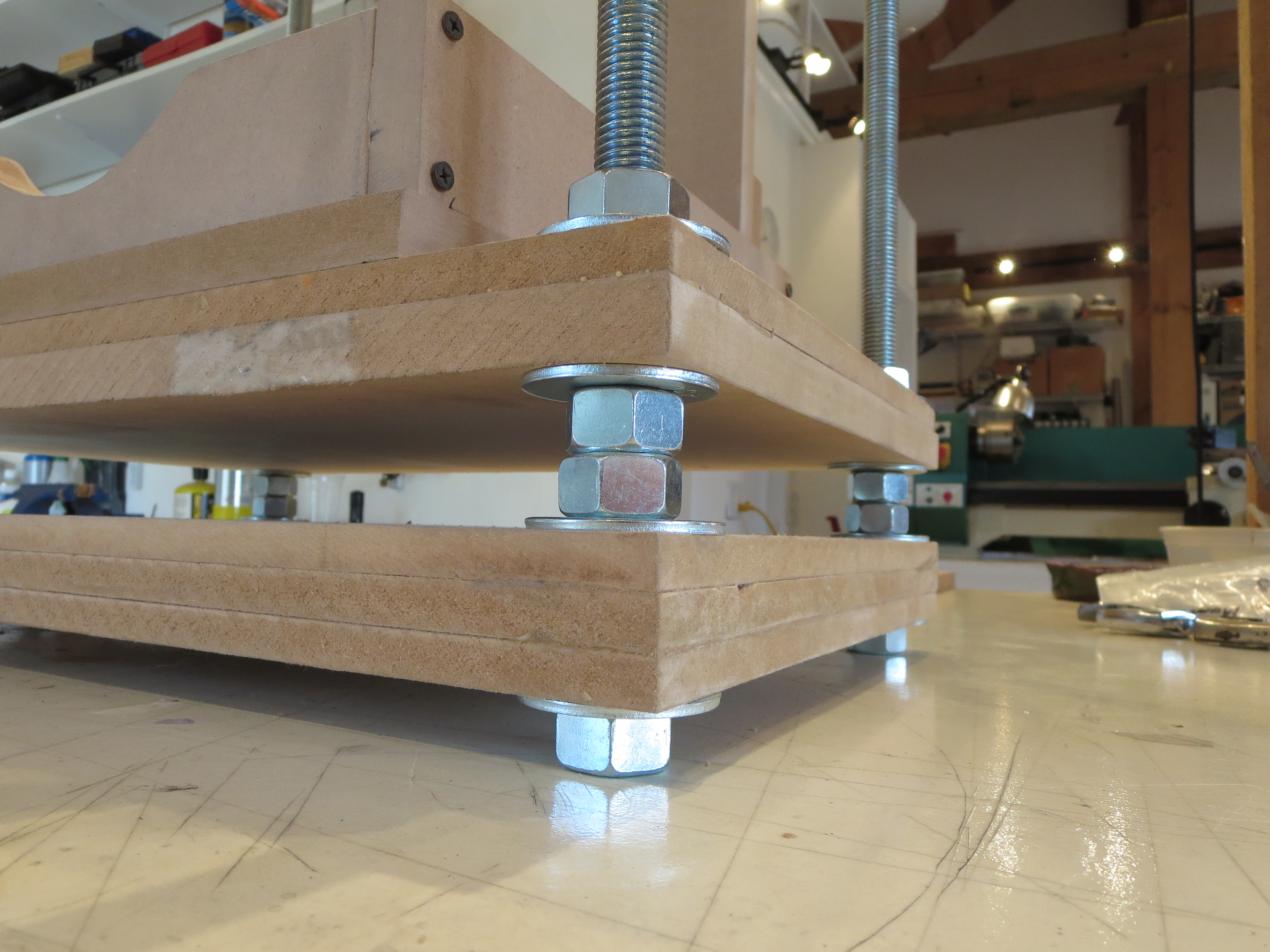
So I went to Home Depot and picked up some 3/4" threaded rod,washers, and nuts. 3/4" is certainly way overkill for the engine's weight, it's more for the stiffness so I don't need much more structure to keep the torsion and twist under control. I had a ton of MDF pieces left over from my CNC router project.
I made a new cradle for the turbine and added another thick interim layer to keep the whole thing stiff.
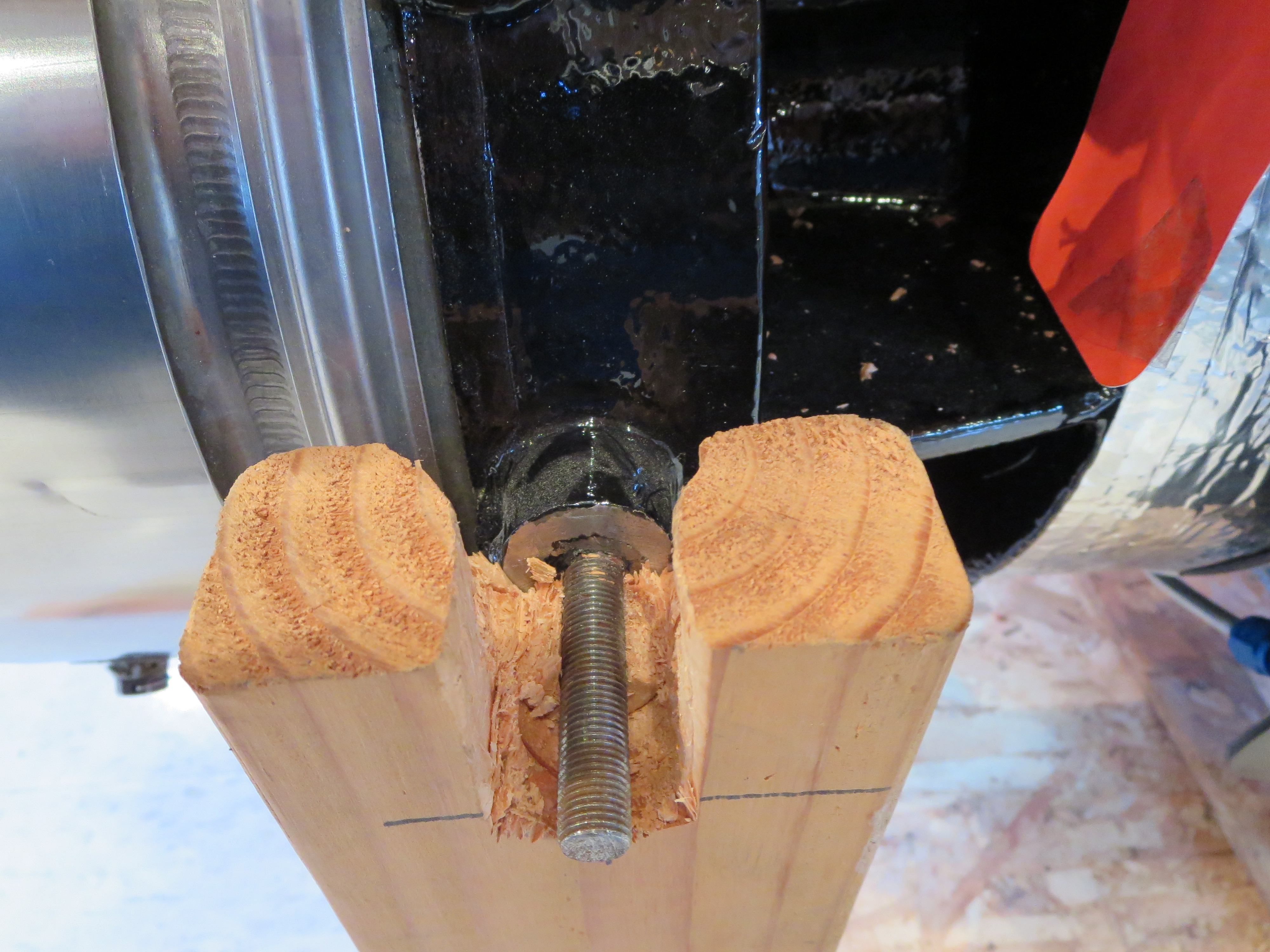
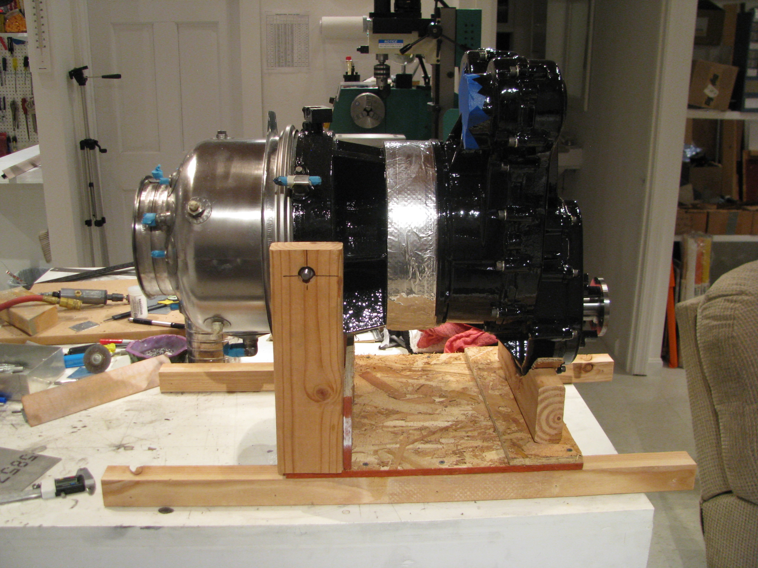
The idea is to transfer the turbine over to this jacking table and use the nuts to incrementally raise the engine up. Should be very safe and allow for very precise positioning.
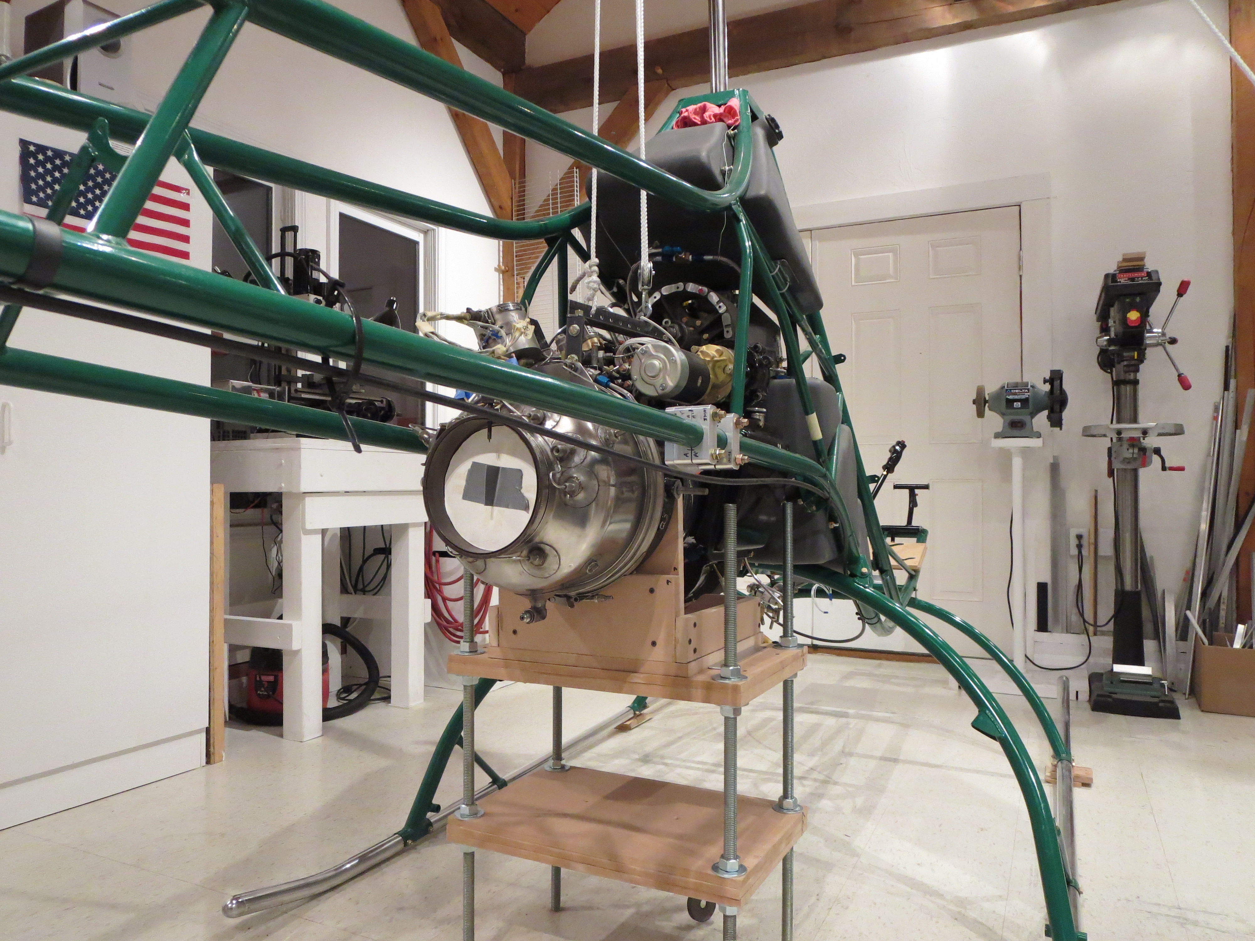
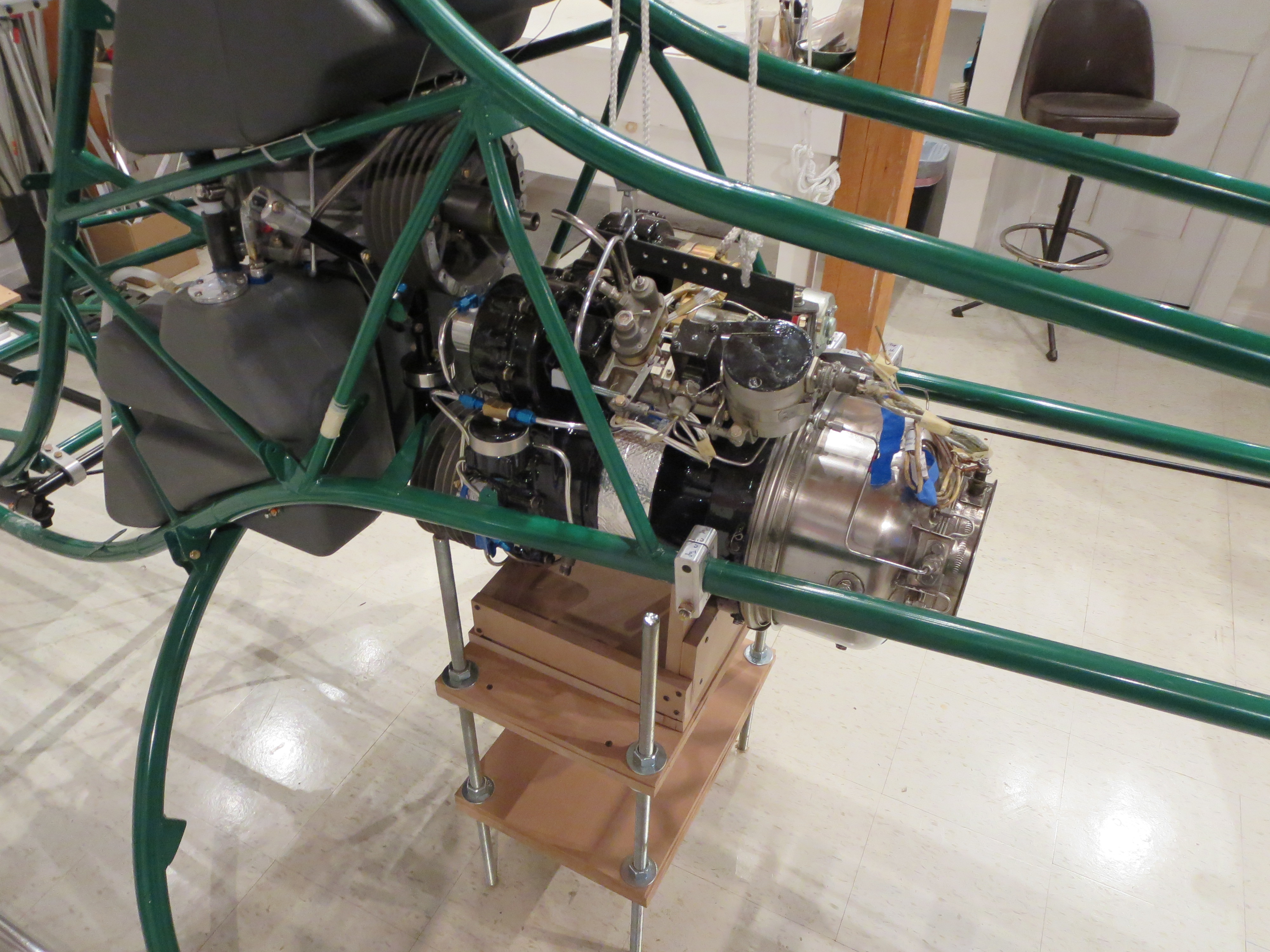
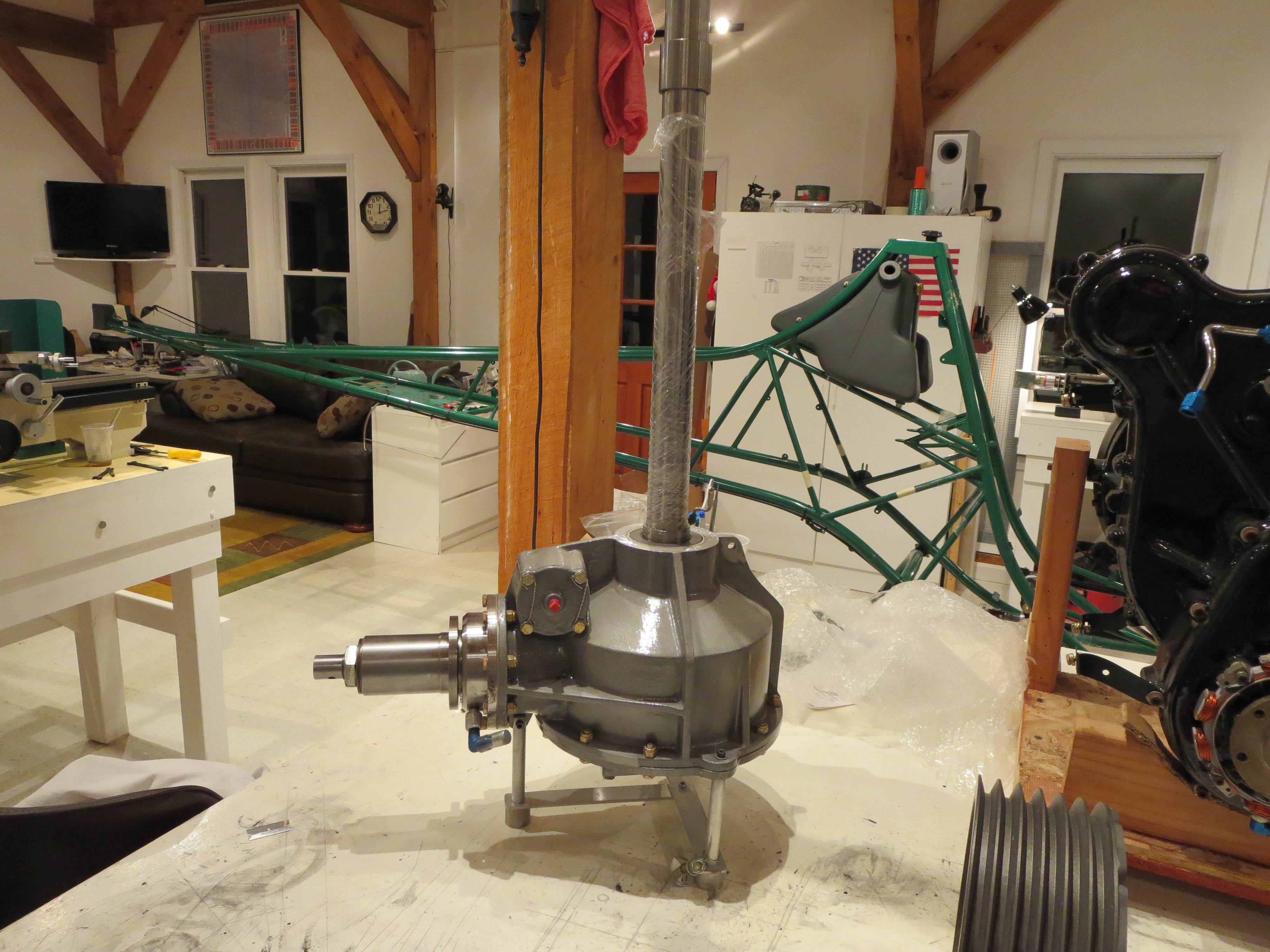
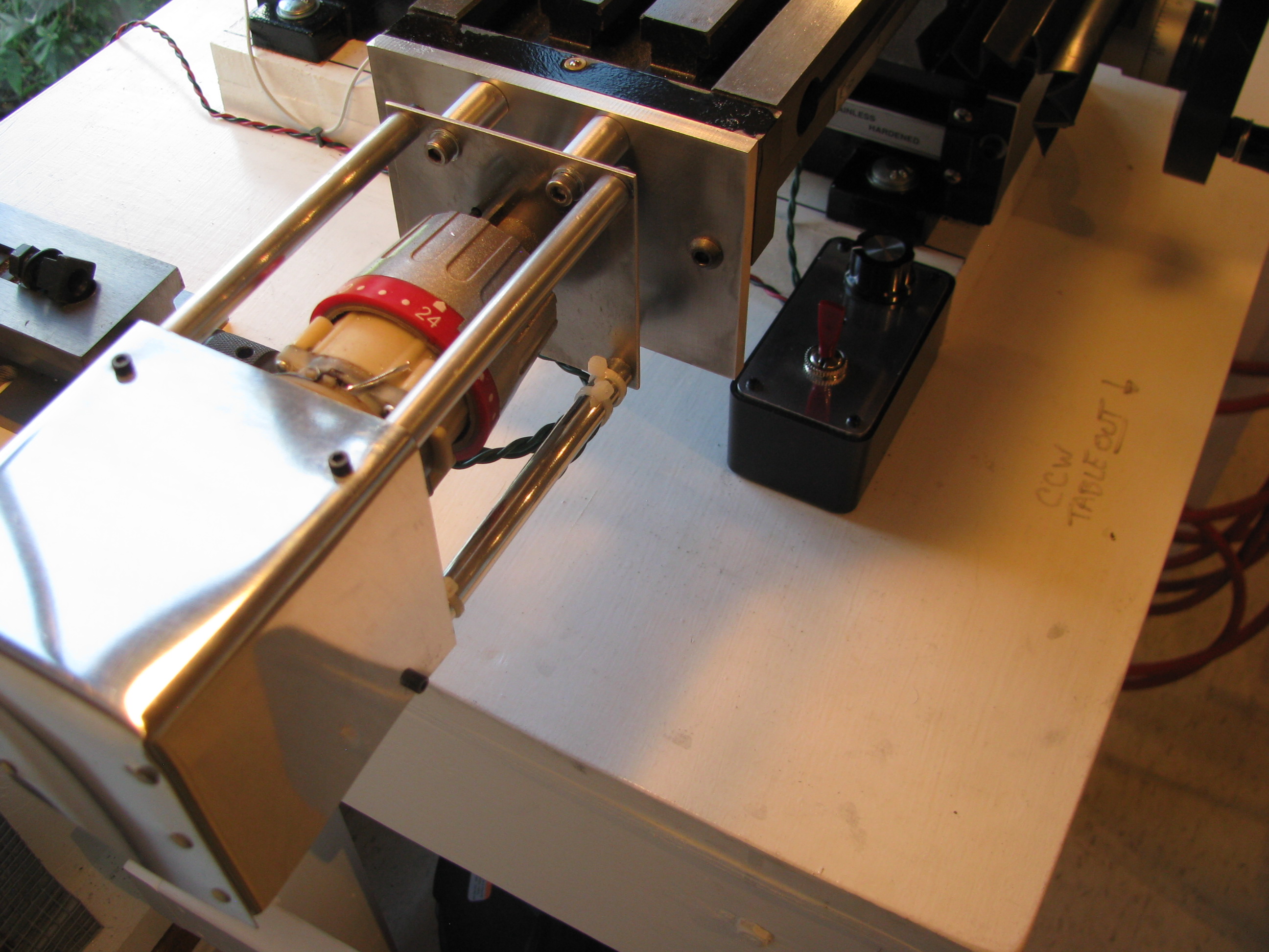
So here is the turbine in position after incrementally jacking it into position. It's very stable and certainly not going anywhere, so I can fiddle with alignment all I care to before locking it down permanently.
HERE is the whole process of building the table and jacking the turbine.
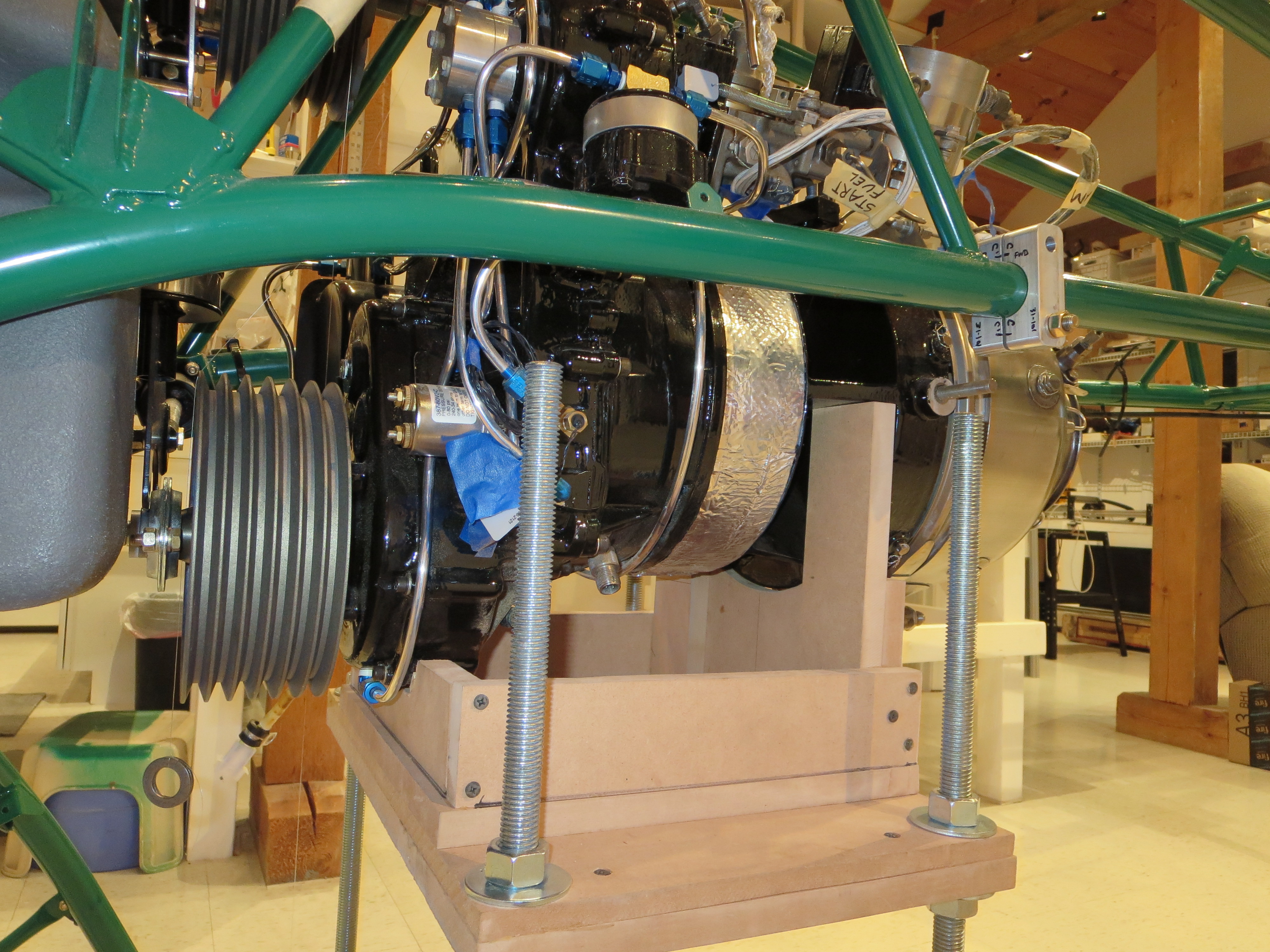
Of course after taking the photos and staring at it I realize I forgot to put the belts on so I will have to lower it a couple of inches and slide the belts on.
Blades are Back
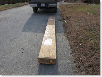
I went to pick up my blades from Conway Freight today. They are back and they have been machined. All I have done is crack the crate and have a peek.
There are no more excuses standing in my way of completion now.
Shop Day
The camera has the ability to monitor for motion, and then push images to an FTP server every second when there is motion detected. I then use an application called "Time Lapse Assembler" to string them into a movie.
Here is a day in the shop. The only frames logged are when I am in view and there is enough motion to trigger the camera, so it is not a full day, but several hours worth. Still, it's pretty big if you chose to download it.
This will get more interesting when there is more action on the airframe. Most of this is engine prep work. With a low-resolution video camera like this it makes for a pretty boring video. I will remedy that soon enough.
Tasks accomplished on camera:
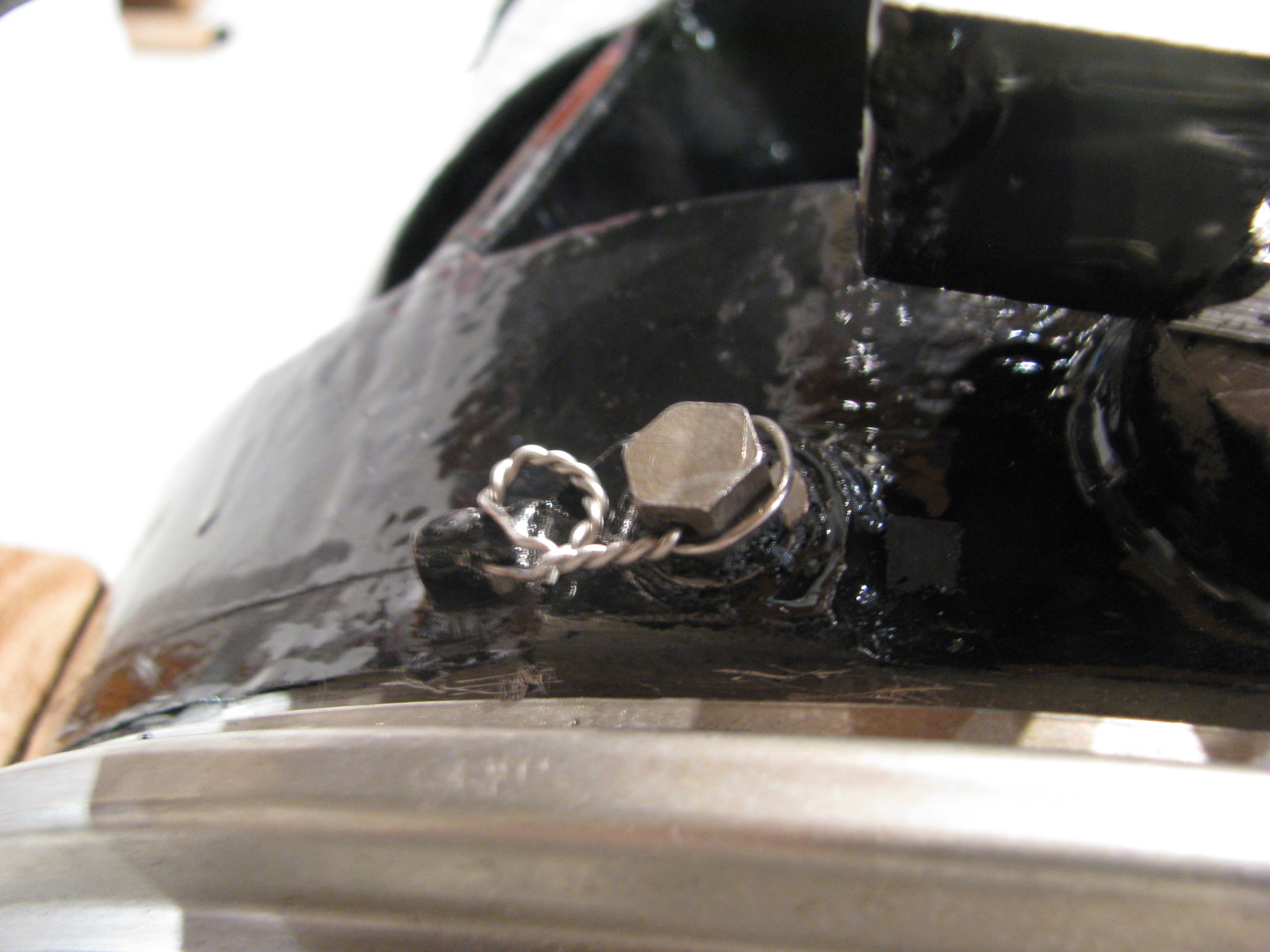
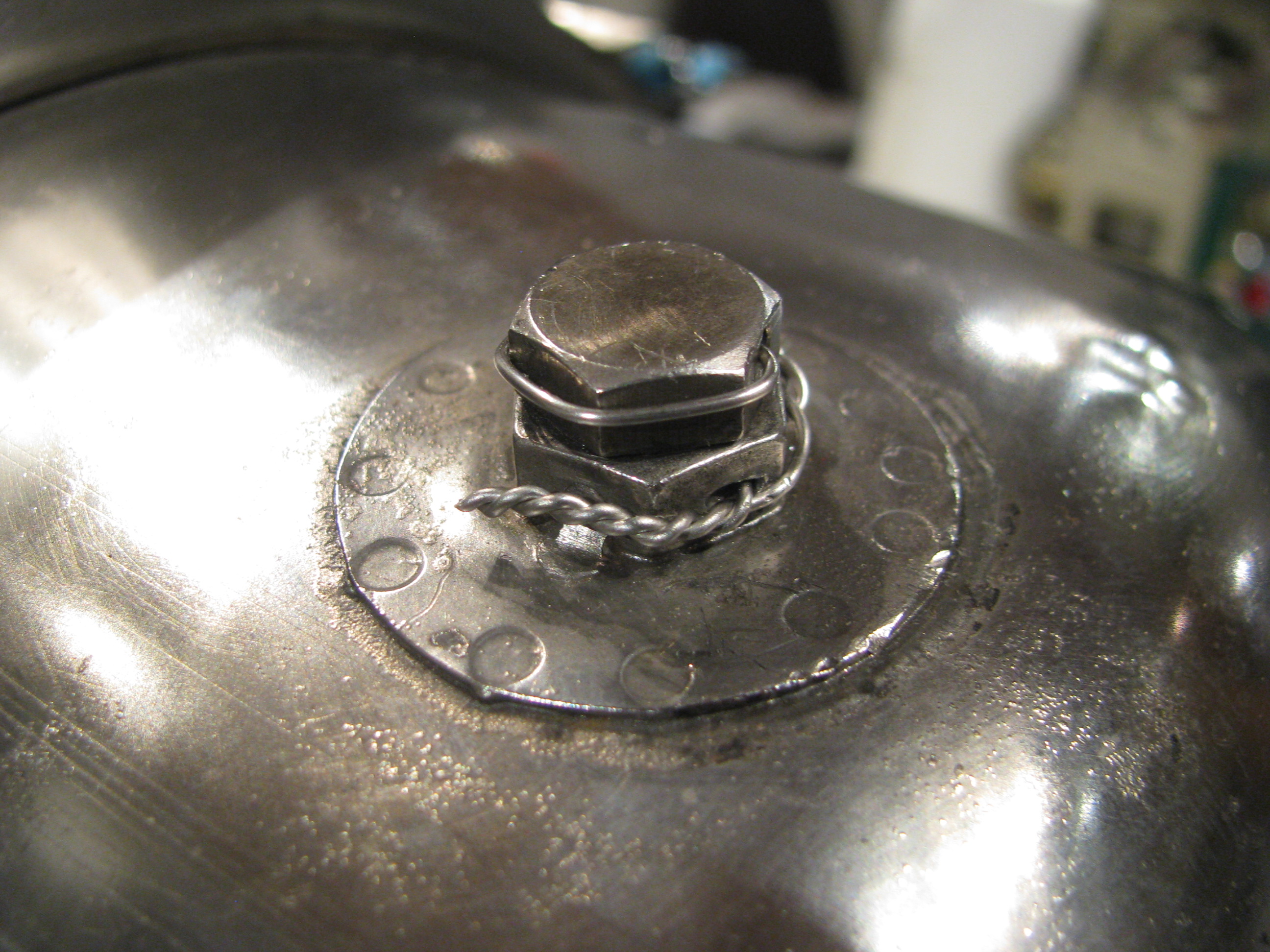
- Safety wiring some engine fittings
- Doing the last bit of engine wiring.
- Torque sealing a bunch of bolts (my way of indicating completion)
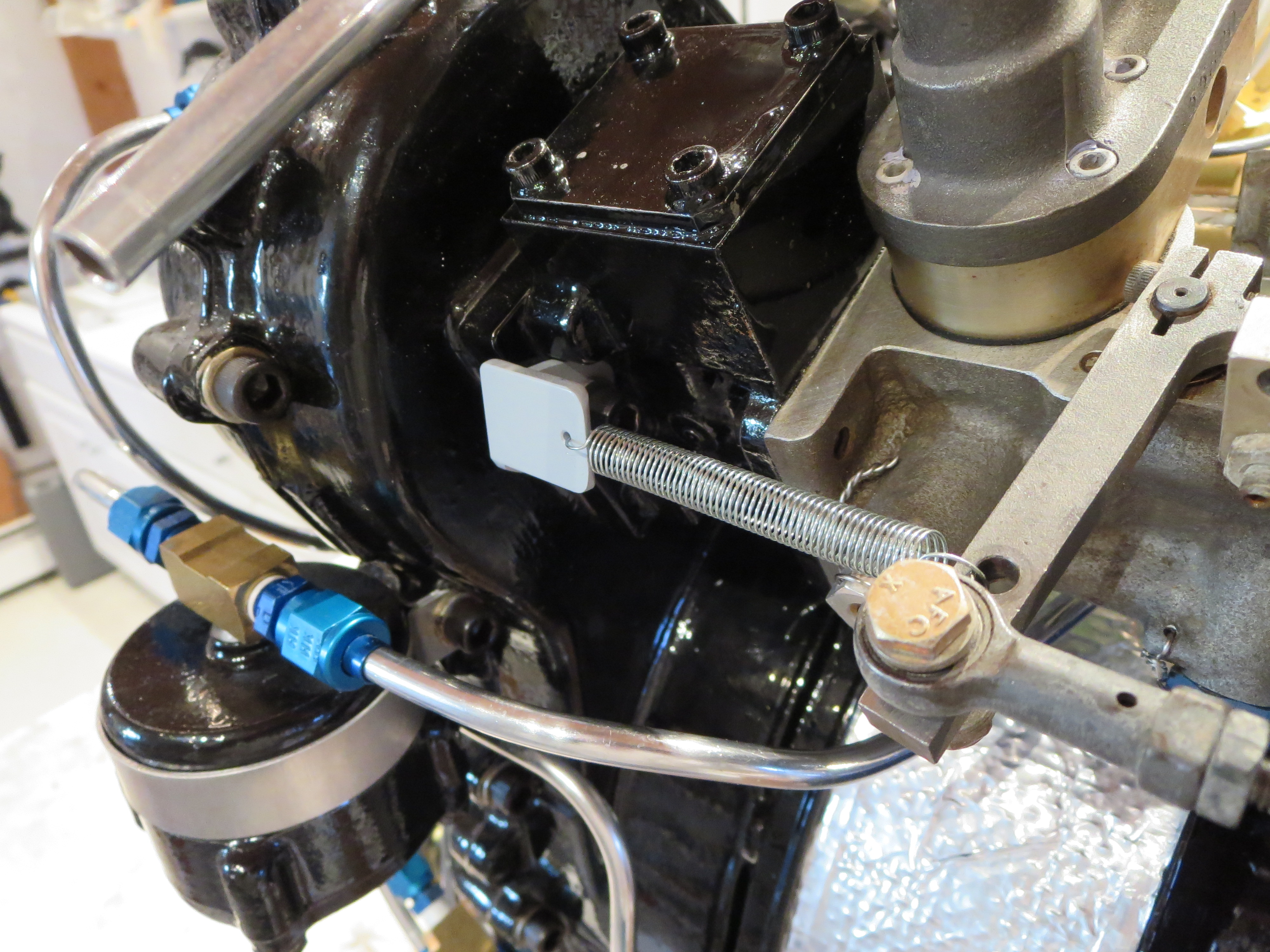
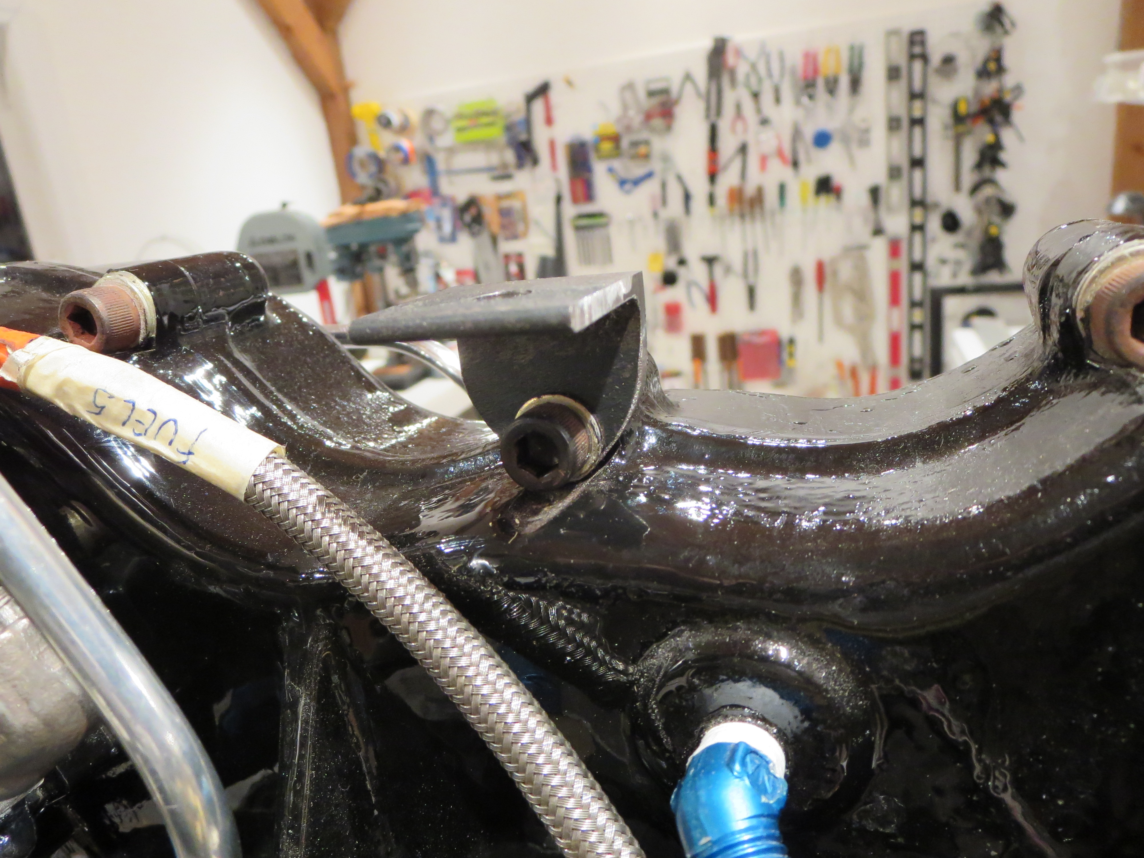
- Fabricating, painting and installing a bracket for the throttle return spring
- Checking the clutch travel and figuring out how it mounts in the ship again.
- Replacing the skid bolts with AN HW of the proper length (the kit-supplied Grade 8 bolts ones are too short).
- Prepping the rubber clutch mount
Engine Prep
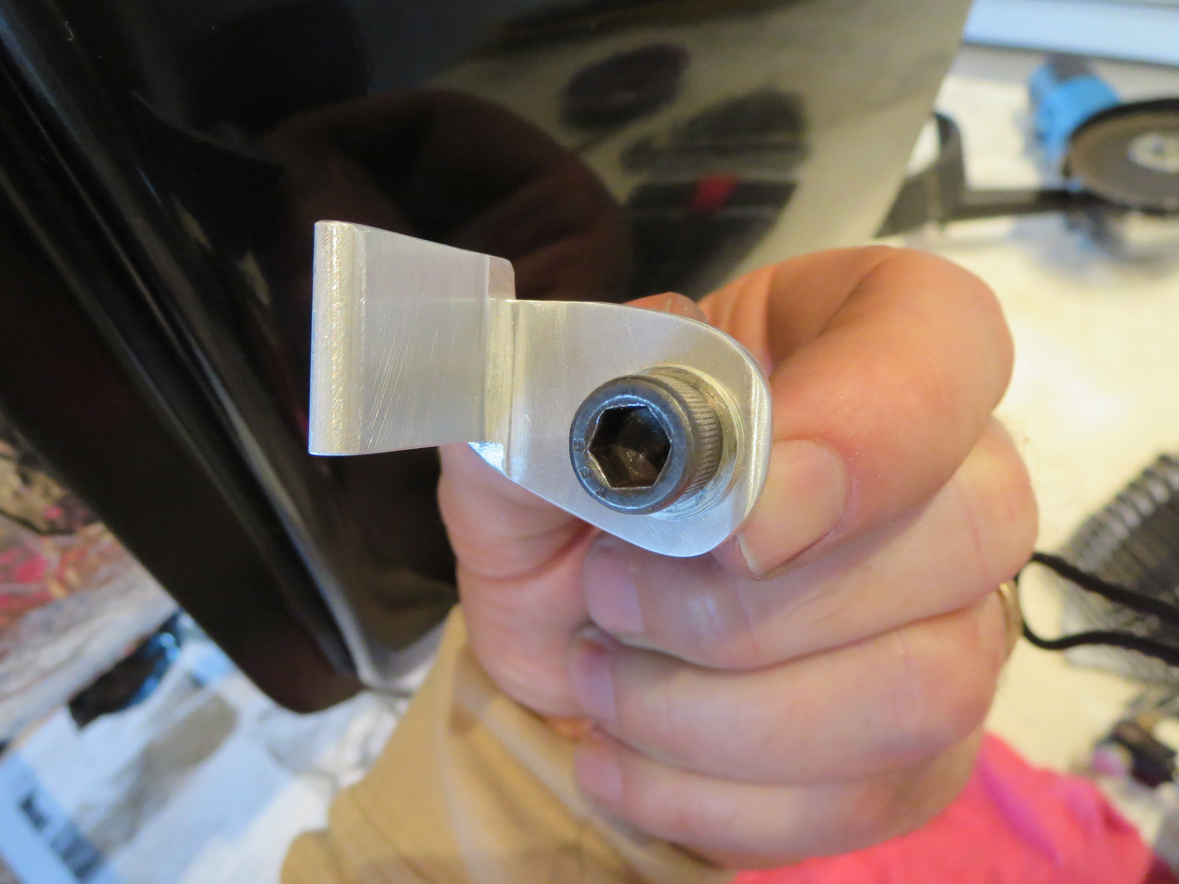
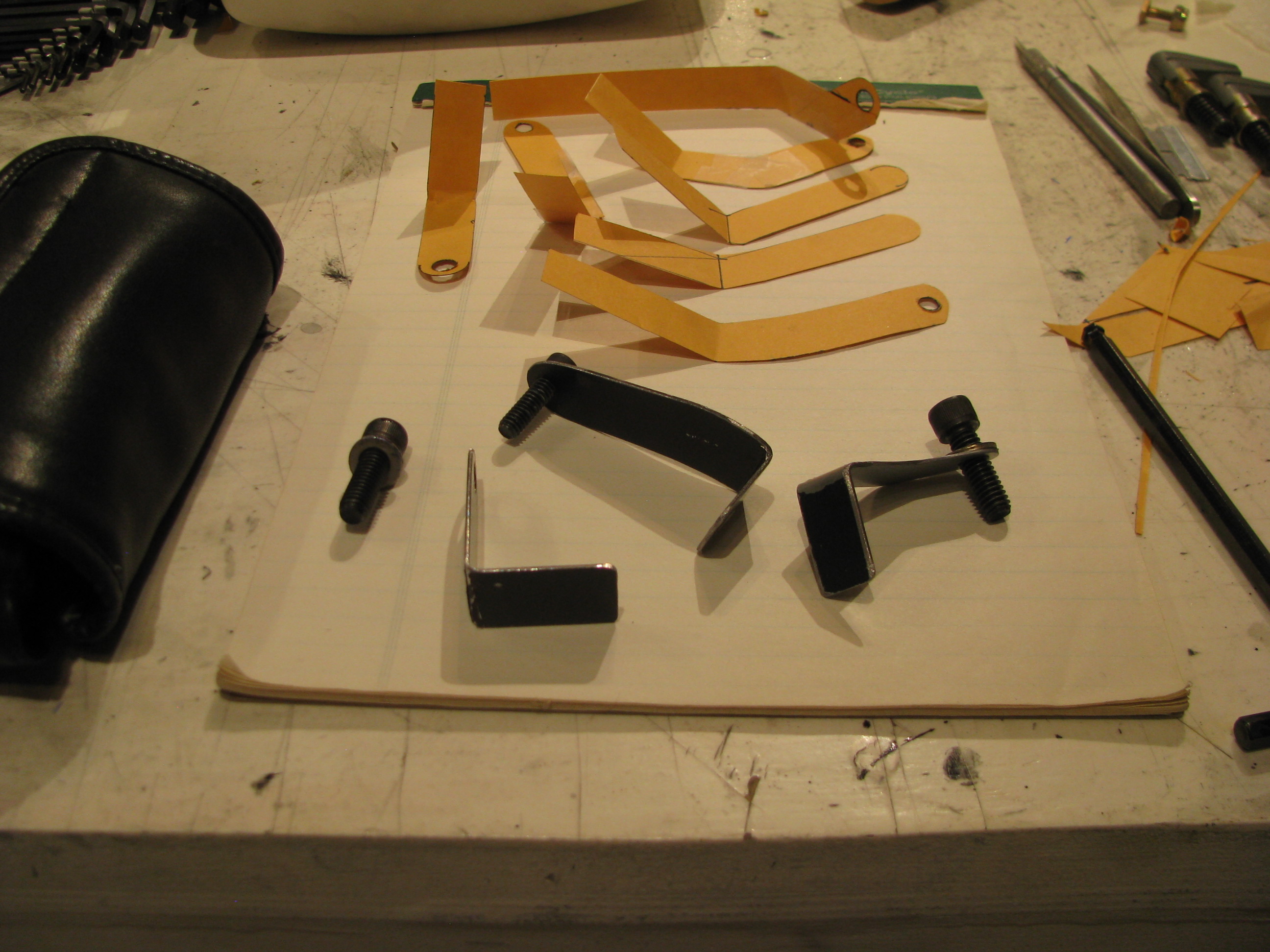
You have to fabricate a little bracket to attach the throttle return spring. I have seen Helicycles that just use a piece of angle here. Well, I shaped and sculpted that stupid little piece way more than necessary.
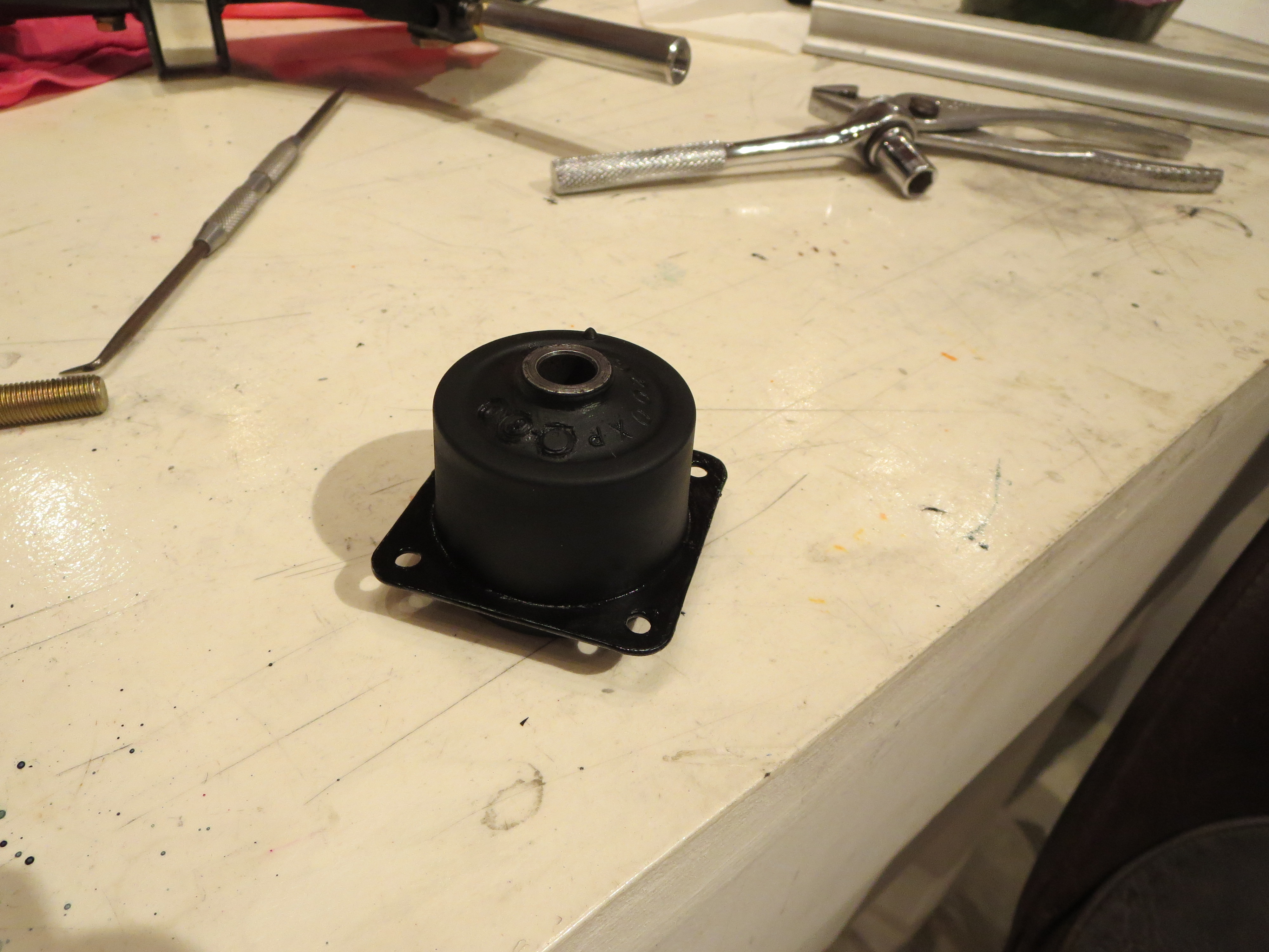
To prep the rubber clutch mount I coated it with Vaseline to loosen the mold-release skin, then rubbed it off the rubber, painted the metal plate (with diluted black nail polish for quick drying), then coated and soaked the rubber in Armor-All to keep the rubber "supple", and lastly coated the bore of the bushing with Corrosion-X. Again, probably overkill since I am sure many just bolt the darn thing in the ship without bothering with any of that.
If you take a half-full bottle of nail polish, top it off with acetone, and shake it up really well, you get a quick-n-dirty lacquer paint. It dries hard as soon as the acetone flashes off. It is not rugged, nor pretty, but for a quick corrosion inhibitor, it saves a ton of time versus real painting.
Engine Hoist Bracket

That's just some hardware store GR8 bolts and angle iron from Home Depot. I had forgotten just how nice steel is to work with. Drilled a bunch of holes since I do not know where the CG of the engine is. This way I can just hook on the closest balance point. If this were a permanent thing I would have used more and better mounting points, but it is a single-use, single-function item.
Oil Tank Buff
Engine Mount Prep
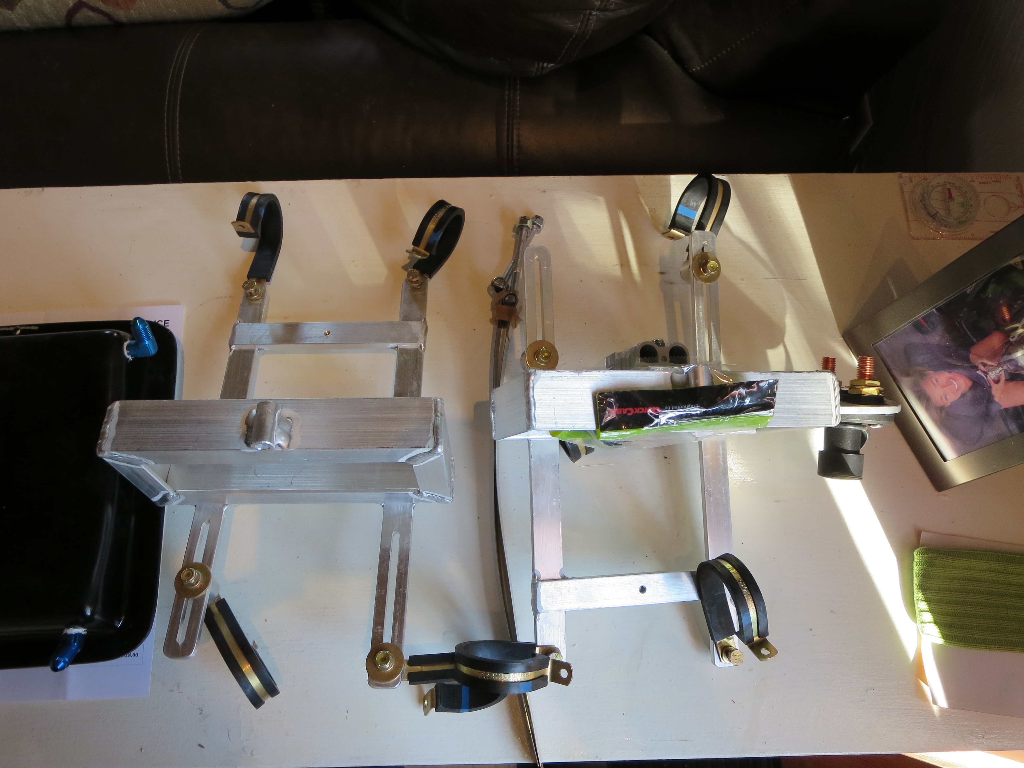
Here are the assemblies for left and right fit together.
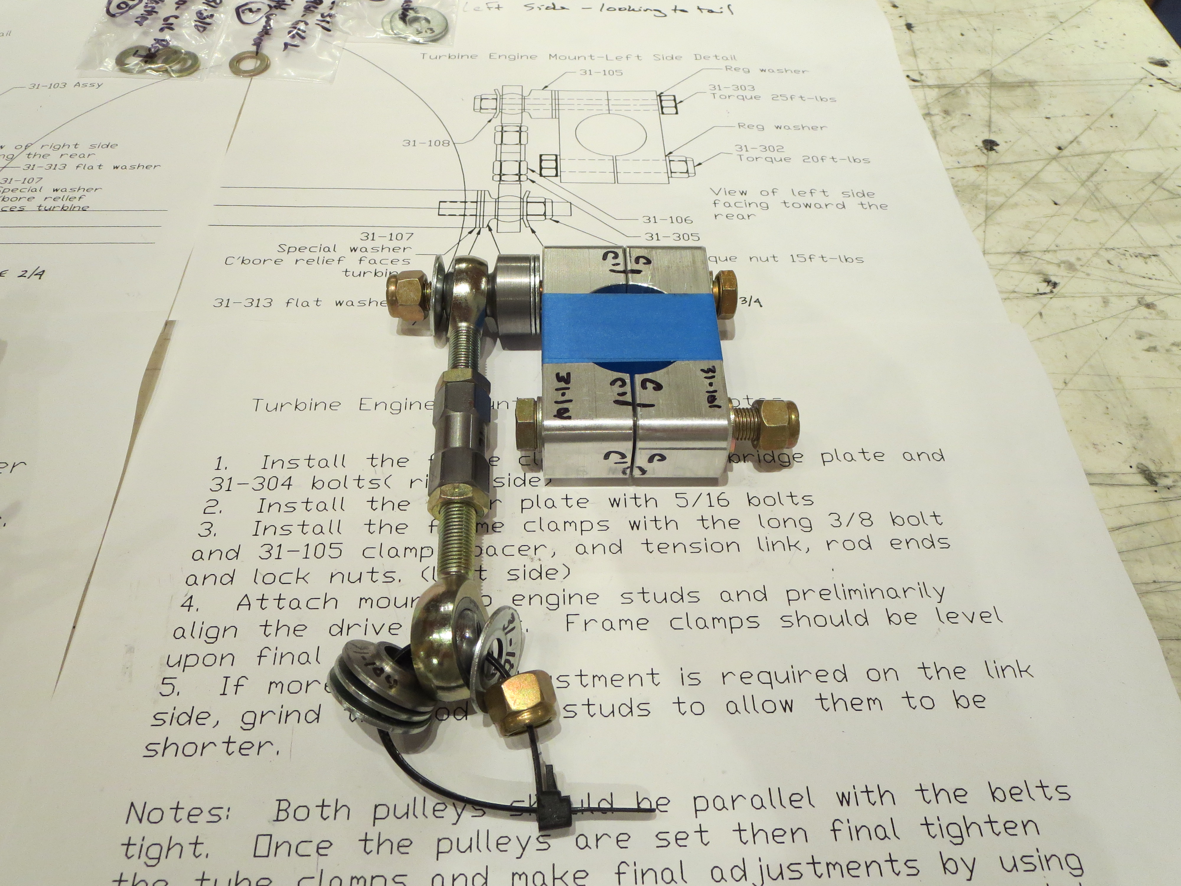
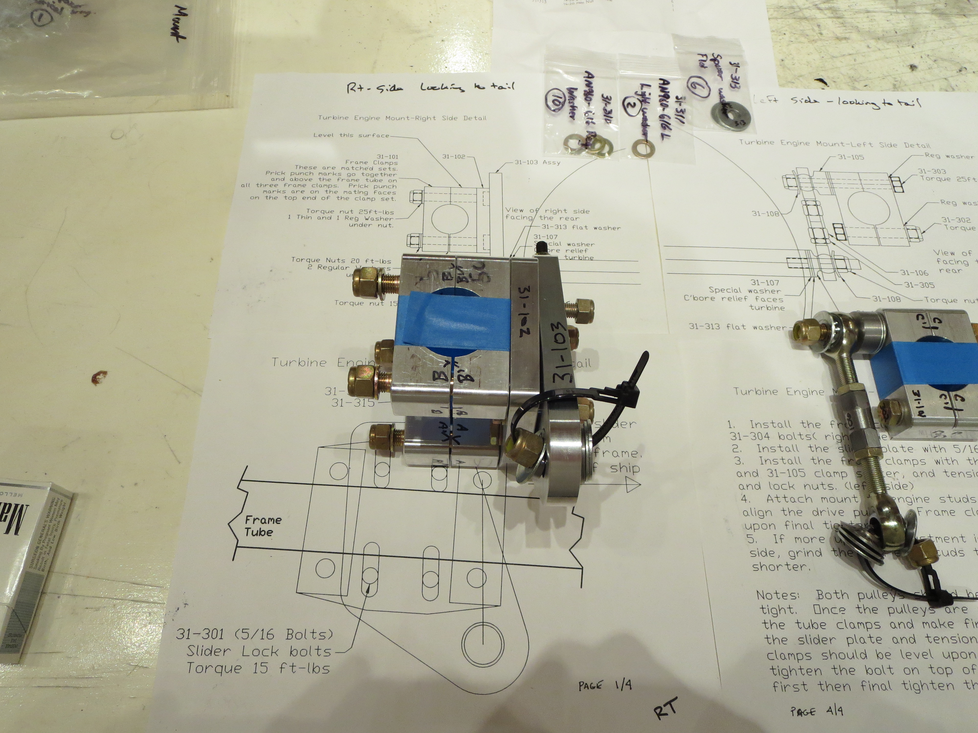
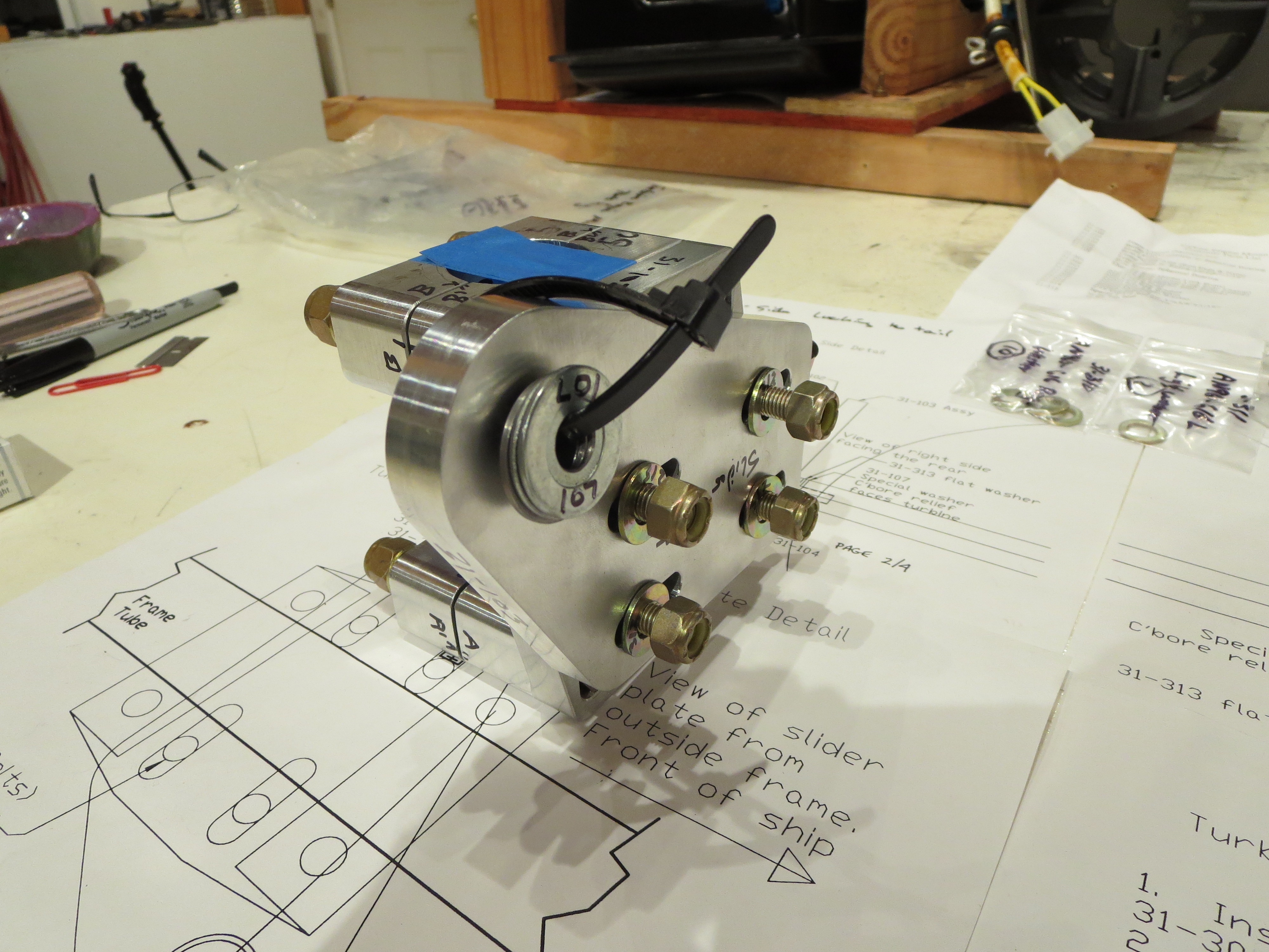
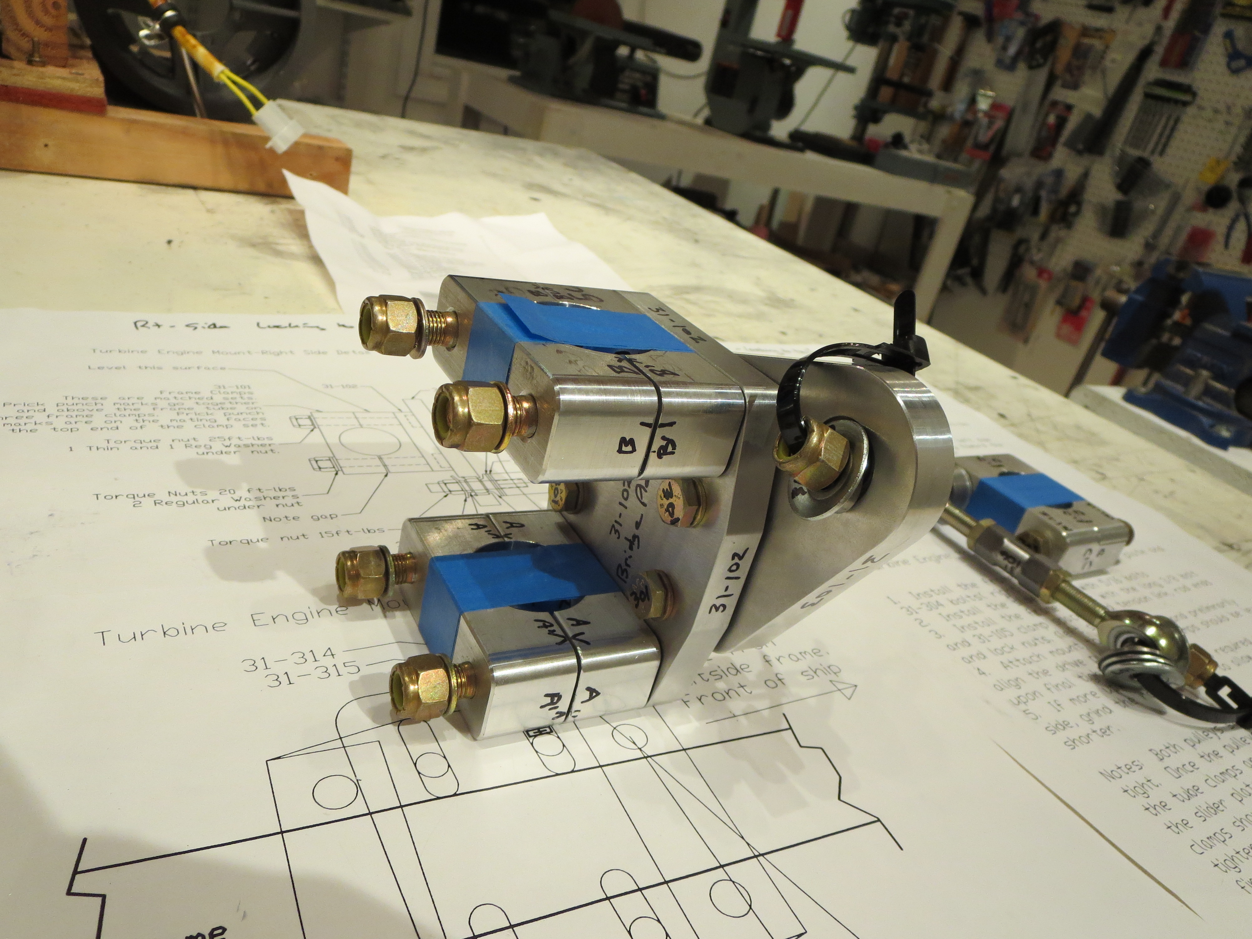
I have a question for Blake as to which way to install the bolts for the inner slider plate on the left side mount; nuts in or nuts out.
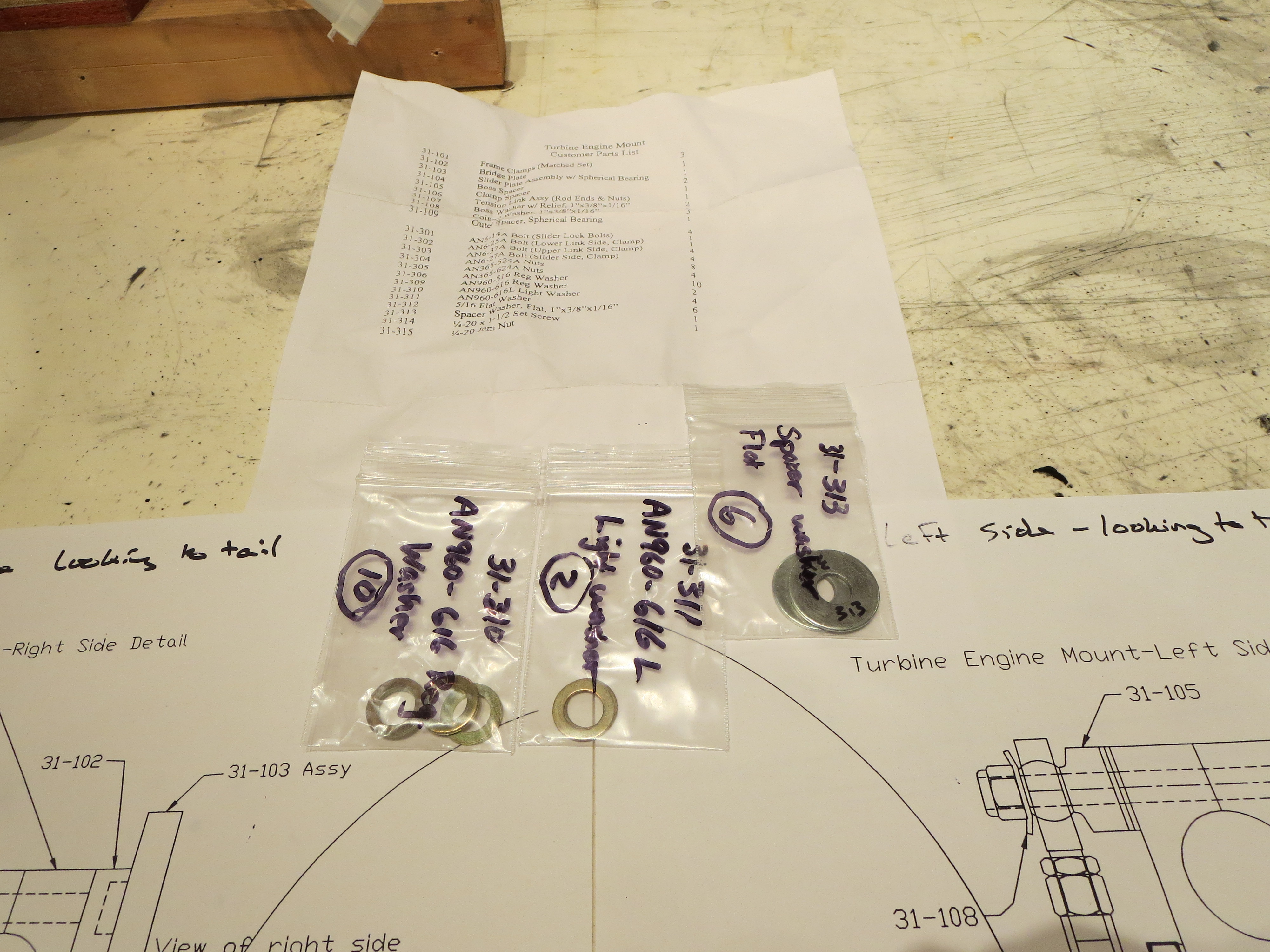
There are a few spare parts, all washers. I am assuming those are for proper spacing once the unit is installed in the ship.
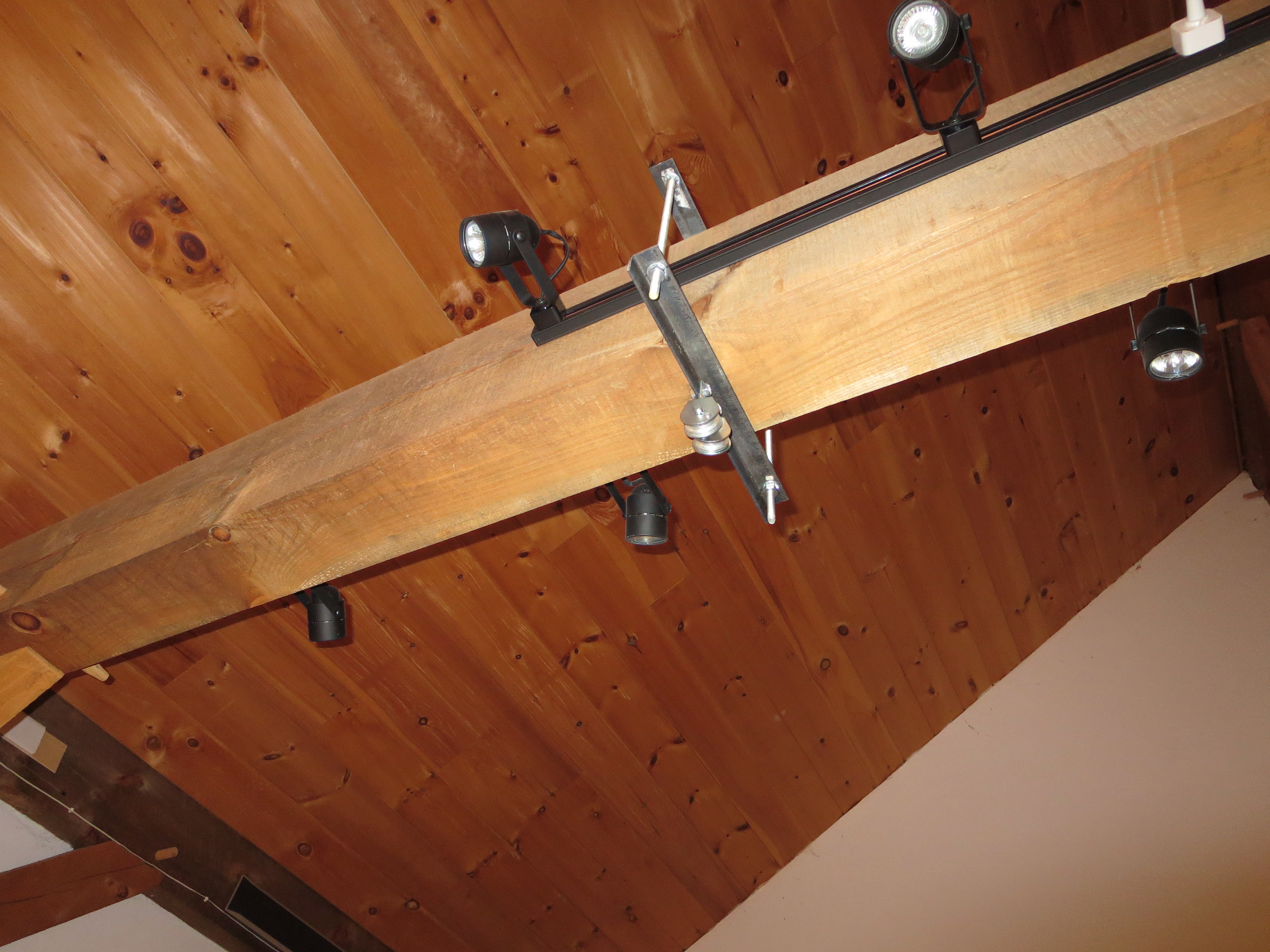
I mounted a couple of heavy steel angles and pulleys to a large beam in my shop for winching the engine up into position.
Next up is to check the gear (since major weight will be on it now), and complete the wiring of the engine, then the mounting starts.
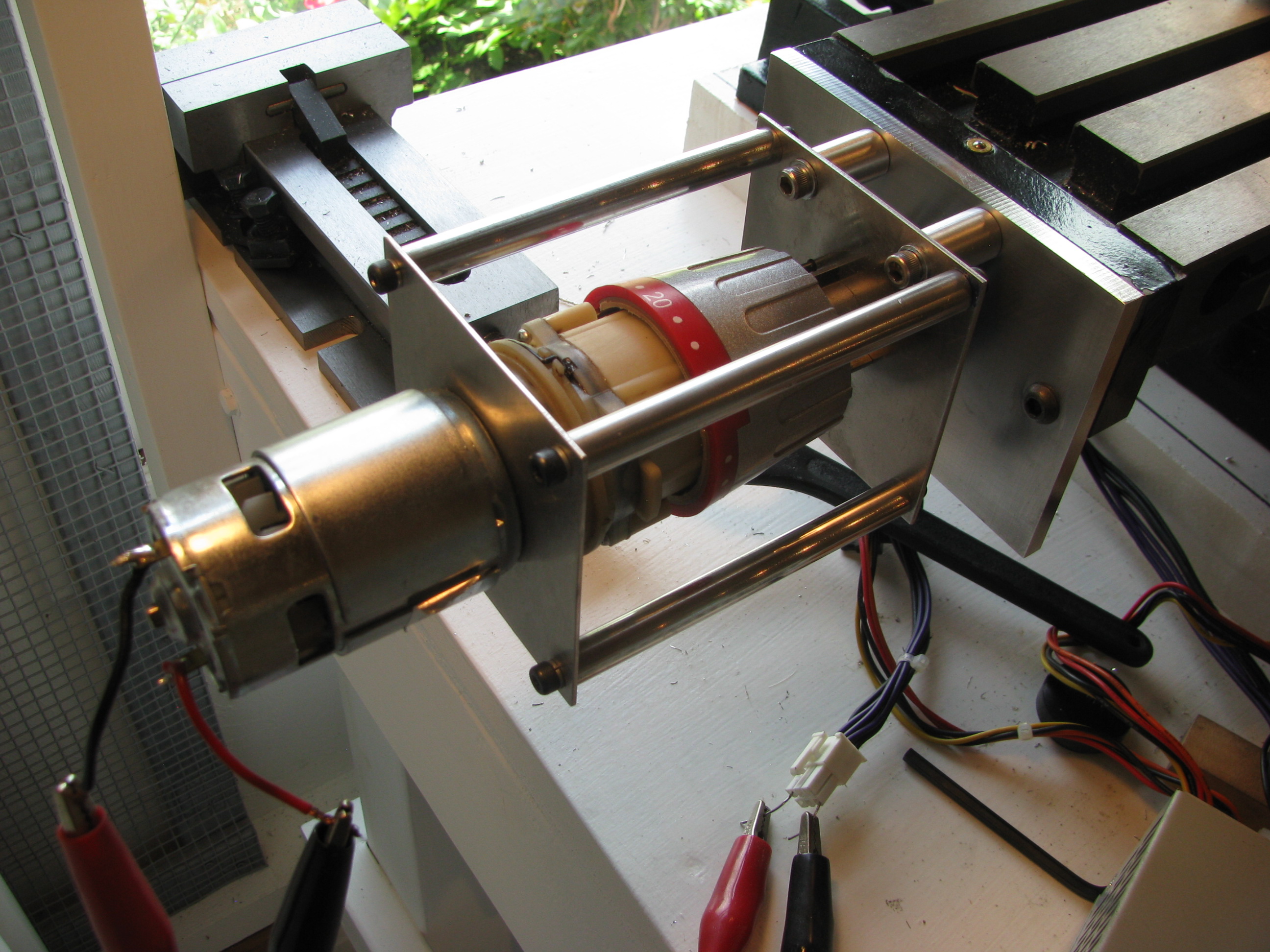
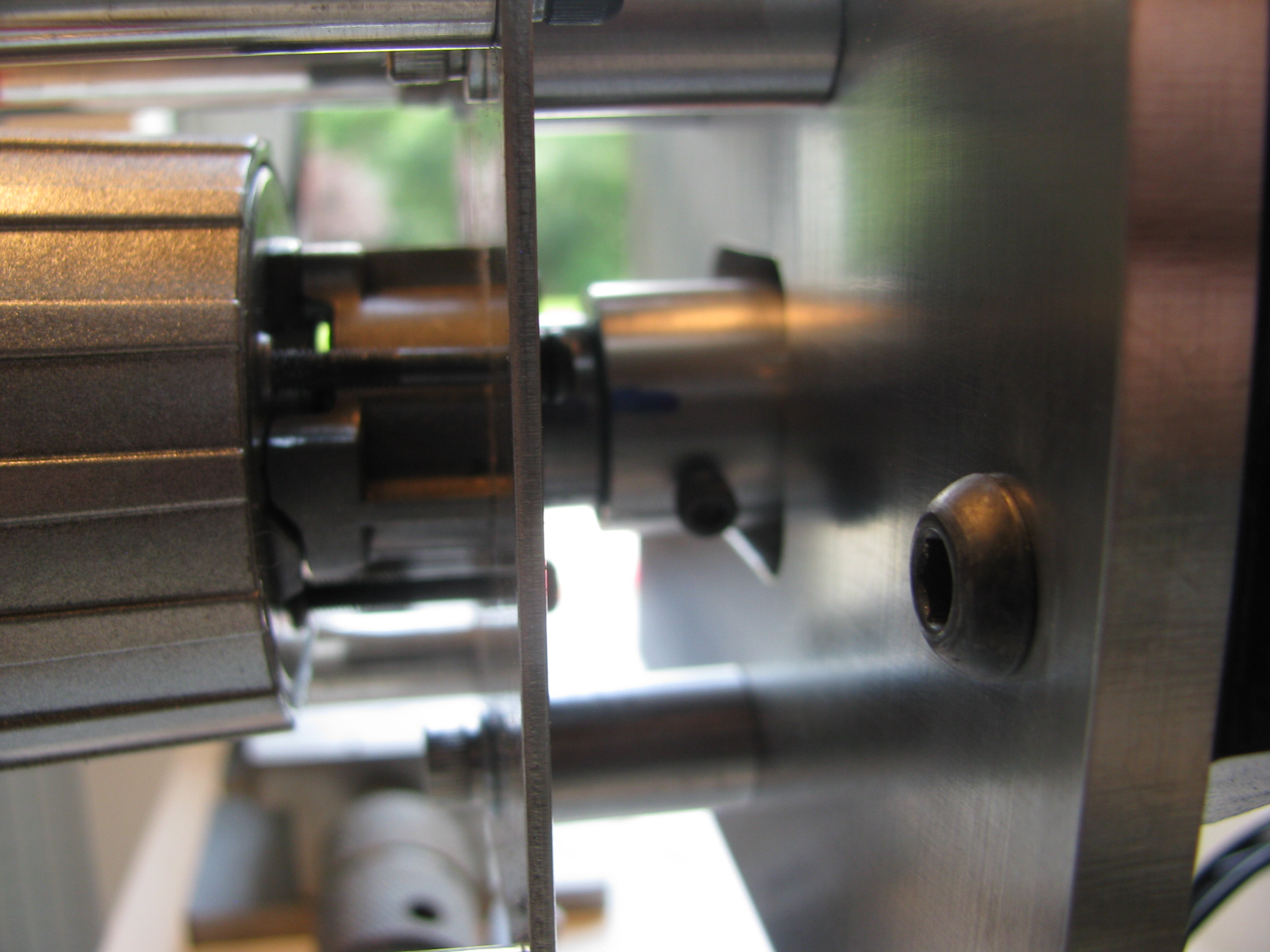
Pulley Balancing
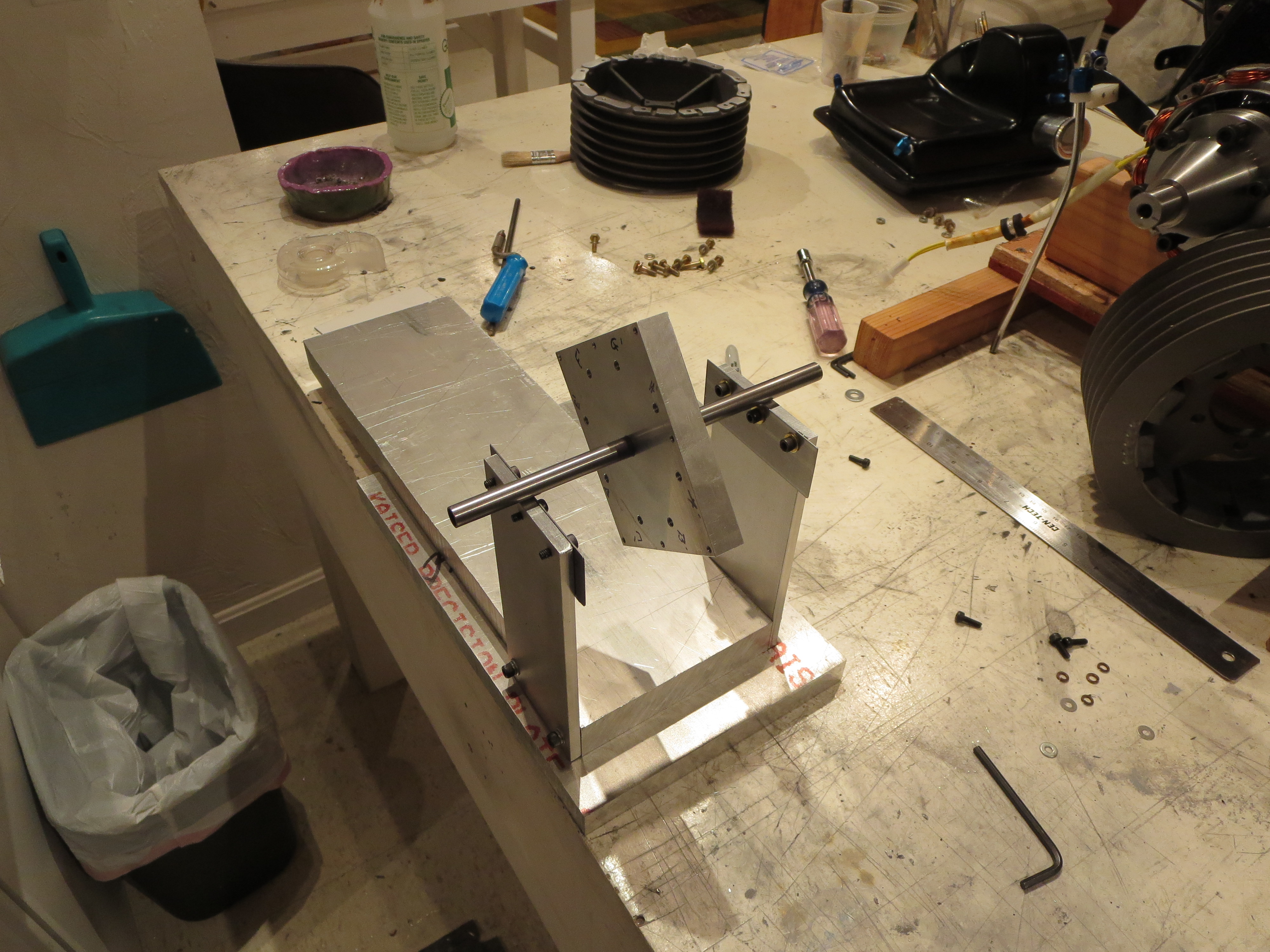
So I built a balancing jig. It's sized for the main transmission pulley and pretty basic. Some heavy stock for the sides and base and two sections of stainless steel ruler (Harbor Freight $1 items) for the "knife edges" sanded and polished on the edges.
The carrier is an "almost" square block. I measured and drilled the bolt holes for the pulley flat face as precisely as I could (again, the mill with DROs is a godsend). All holes are +/- 0.002" of their ideal position. The center spindle is a piece of 4130 steel tubing. I drilled the center hole slightly undersized and sanded up to a super snug press fit. Once pressed in the tubes were sanded and polished.
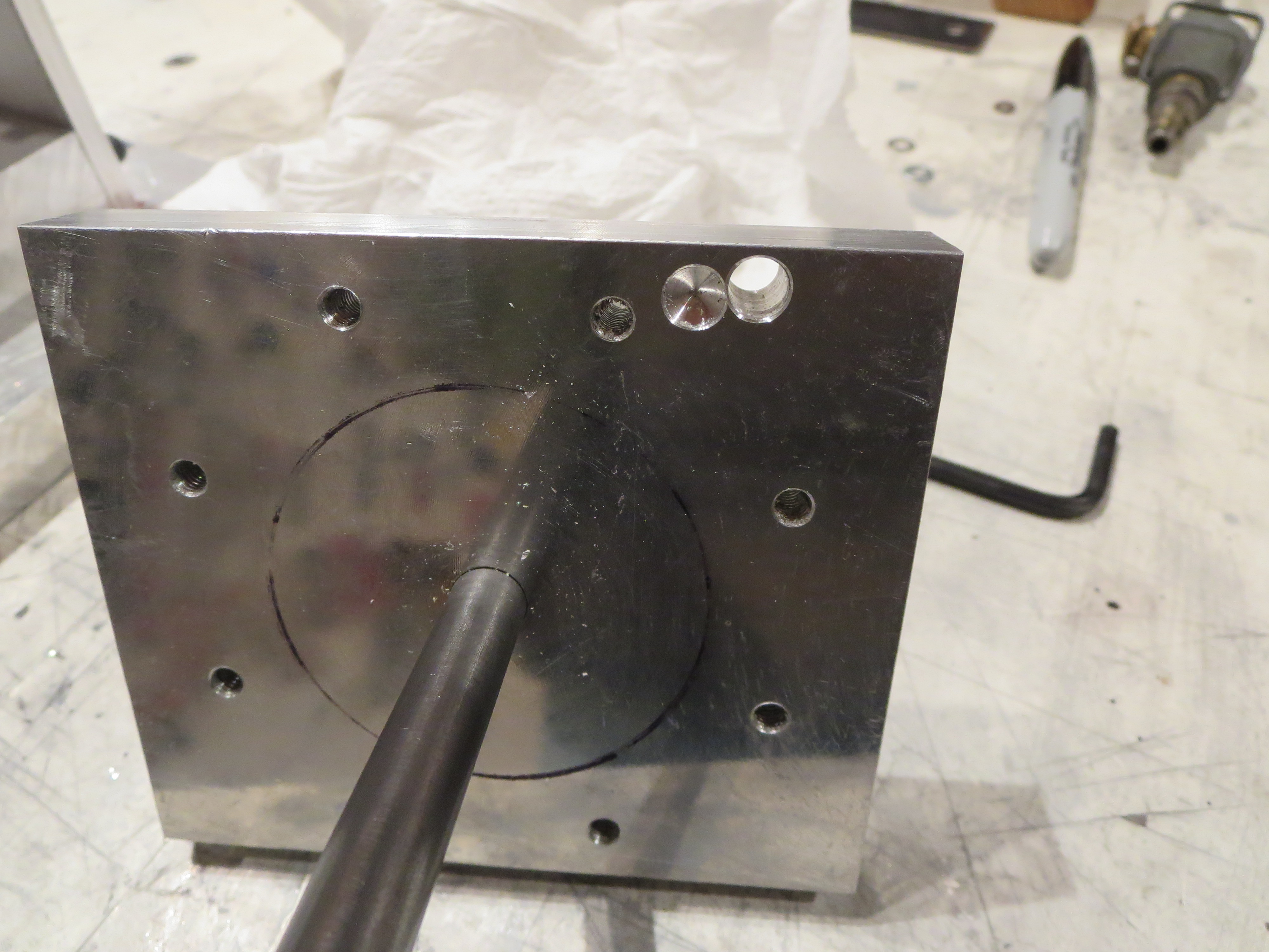
Next, the carrier assembly itself has to be balanced as perfectly as possible and the jig leveled. The through hole and the partially drilled hole achieved that balance. There were already some partially drilled holes on the other side of this block, and the drilling ops are not perfect, no matter how carefulIy it was machined. This is a very important step. When the carrier spindle is balanced you can level the jig with shims to be perfectly level. Even the tiniest of differences causes the balanced item to roll off one side or the other. It's pretty impressive how delicate/accurate this thing is.
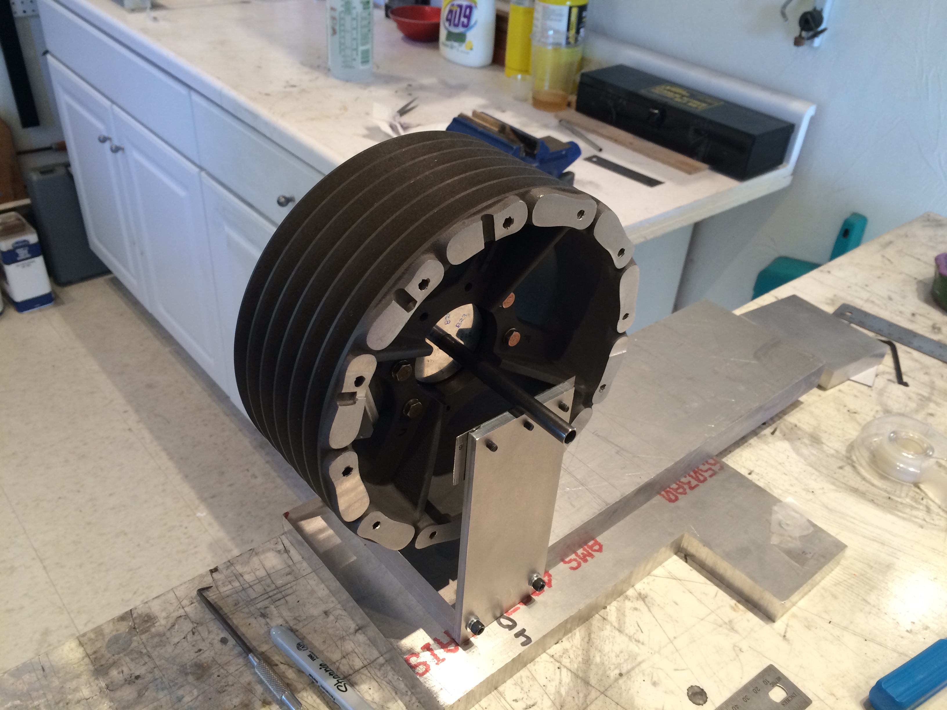
Only THEN can you start balancing the pulley. Bolt it together, see which side is down, mark it, redo the measurement with the carrier at 4 90 degree points, then draw lines across the face of the pulley. The center intersection point is the center of gravity. Since the carrier is not perfectly centering, you must do four measurements at the cardinal points and then draw the centroid. Only THEN remove material on the heavy side - a little at a time - then repeat.
It took several hours, but I am quite satisfied that the balance is WAY better than anything achieved taking the pulley right out of the box, especially if you bolted those hand-cut cooling fins on. I am pretty sure it is now within a gram or two of perfect balance.
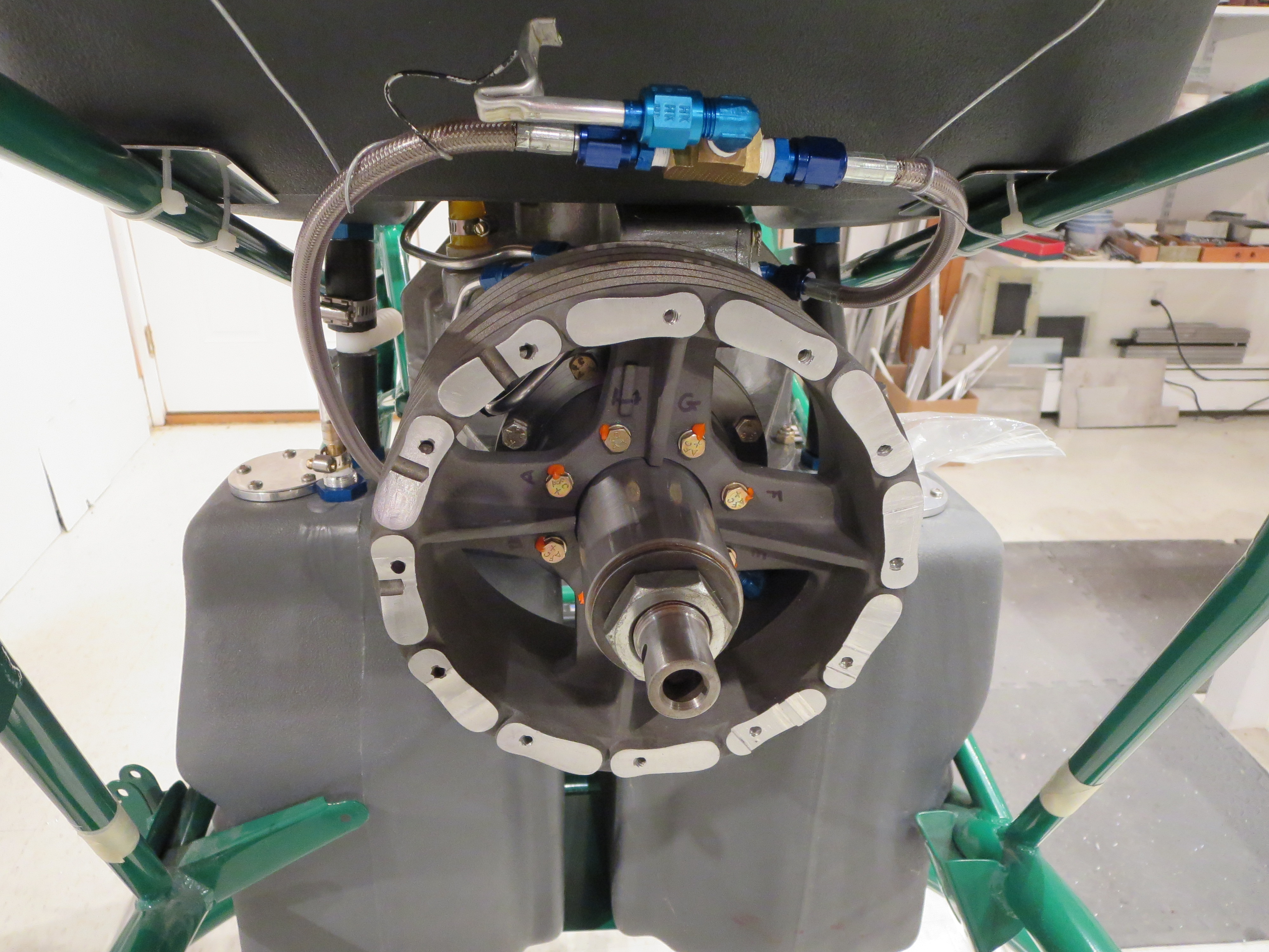
Bolted, torqued, and torque sealed in the ship for the last time! Another "final assembly" thing down. On to the engine!
Last SP Priming
I also spent a whole lot more time tweaking the gun for a good spray pattern and quantity. This is kind of a matter of feel as much as anything else.
The interior of the cabin will be painted with a Rustoleum "Simply Stone" textured paint. It's kind of like spatter paint from old car trunks. The seat pan top and instrument pod will be satin black for low reflections.
More SP Priming
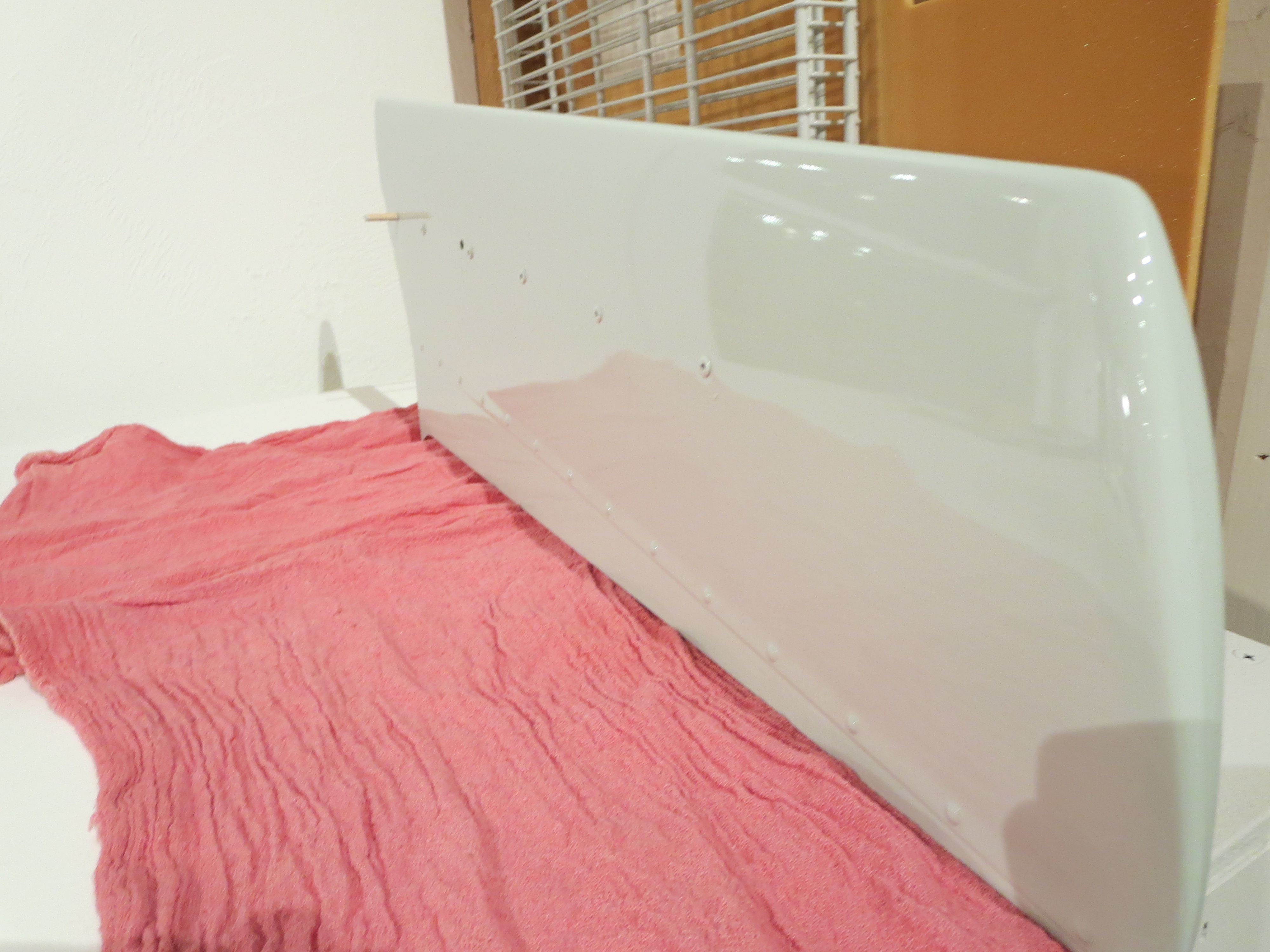
DISASTER. Right when I was thinking this painting stuff wasn't too hard, this thing turned into a runny, saggy, ugly mess.
Yuck! You can see the sags, runs, and droops.
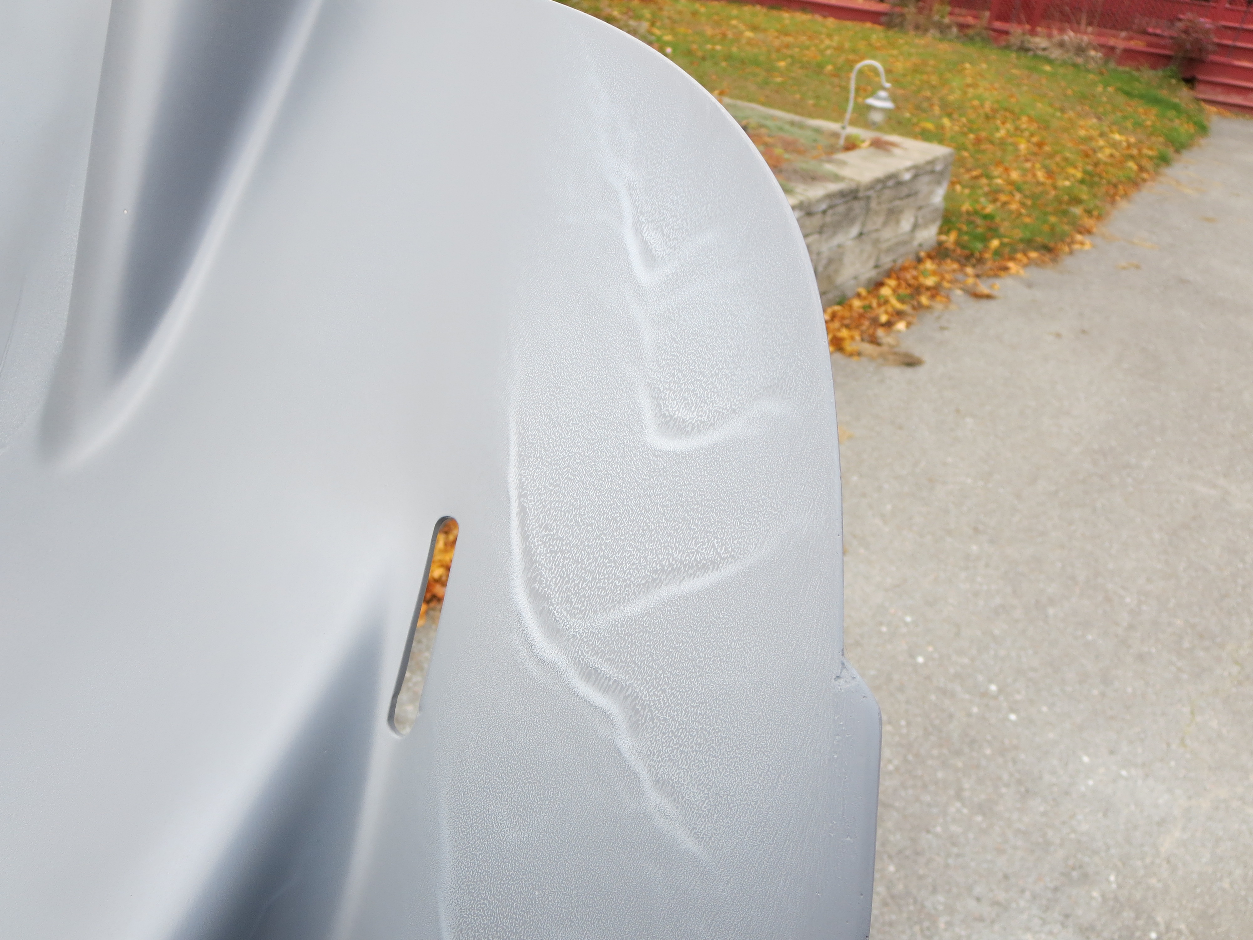
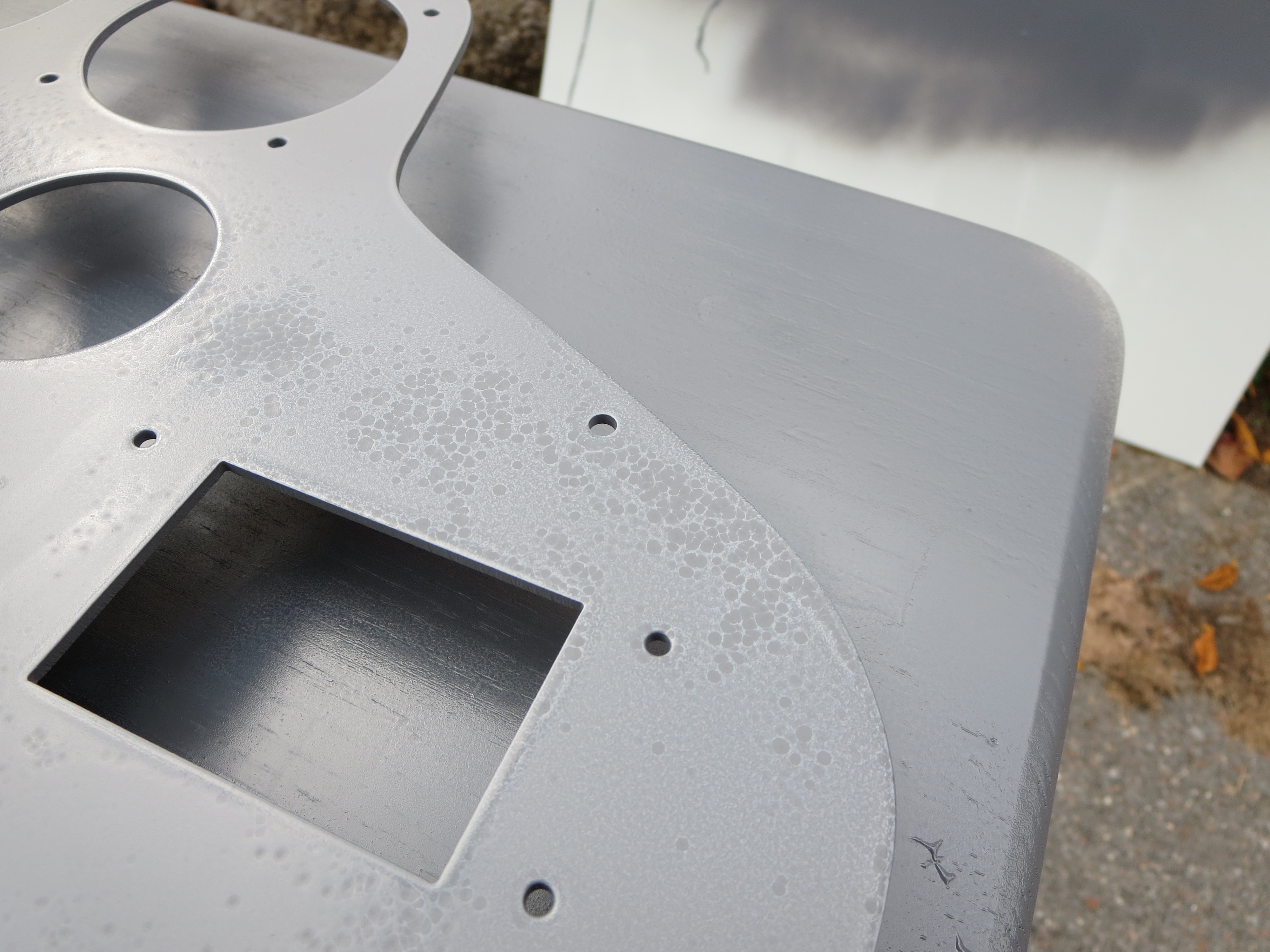
This is the cut panel blank which I primed as well. Those aren't really fisheyes. They are more dimples.
Very rough texture when dry.
Conclusion: Weather, weather, weather. Whereas when I primed the rear of the pan, the day was sunny and dry, the day I did the top side was cloudy and overcast and the humidity was relatively high. It was supposed to rain that afternoon and I wanted to get the primer on before it turned wet. Because of the moisture in the air and the lack of sun I think two things happened. 1) When I did my final wipedown with IPA, it never evaporated all the way. I think that is why the panel has the dimples. There was still residual IPA in the pores of the aluminum. 2) Because of the moisture and lack of sun, the primer did not dry or flash as quickly. The longer to stayed on wet, the more it sagged and ran.
This epoxy primer is tough stuff, so this will be laborious to sand off and start again, but that is the price to pay for getting too cocky about painting. At least it was the only primer. My lesson is learned and I will redouble my attention to conditions.
Lesson learned.
Seat Pan Rear Priming
I broke out my Eastwood 2-part epoxy primer for a quick couple of coats to seal the rear of the pan. This stuff flows nicely and surprisingly almost exactly matches the color of the plastic used on the fuel tanks.
I am not too concerned about the finish on the backside of the pan. This is just a sealer, for the most part.
Reno 2014
I attended the National Air Races in Reno this year (2014). In the display area were two different Helicycles. This was awesome as I have been to a number of Sun-n-Fun and Oshkosh events, and have seen exactly ONE Helicycle at Sun-n-Fun in 2013 only. There were two on display at Reno this year, an official corporate presence, and information on the Helicycle that is being used as a drone. A wonderful showing.
The first machine was Blake’s personal machine from Eagle R&D. This is a basic workmanlike machine that is actually a collection of parts from a number of builds. Here is a slide presentation of Blake’s Factory machine. They may seem like a random collection of photos. They are of whatever was interesting to me at the time.
The second was James Kent’s machine. This thing is a work of art. James has added a number of very advanced enhancements and is finished to a supreme degree. Polished surfaces, chrome plating, and superior craftsmanship really makes an outstanding impression. I didn’t get as many photos of Jame’s machine as I have a whole bunch from Reno a coupe of years ago. Here are a few detail shots of some of the nice touches.
James’ machine was absolutely swamped at the show every time I walked by.
Oil Cooler Endcaps
Here are the end caps to the Hap Miller supplied oil cooler. This labeling is not strictly necessary, but a start.
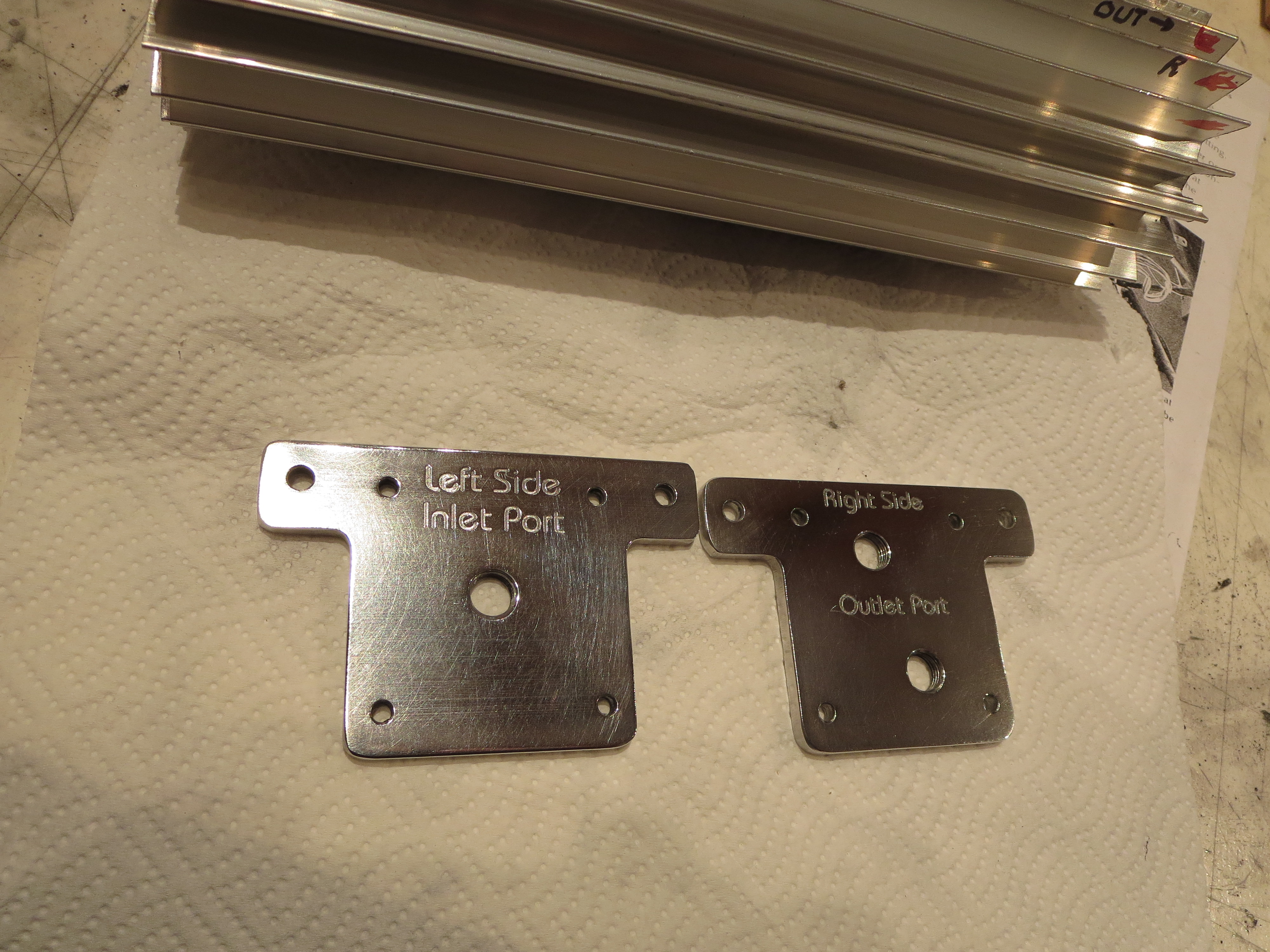
That's just a quick "shop polish". A camera angle that highlights the engraving also highlights the unpolished scratches in the aluminum. I am thinking I will just leave the oil cooler extrusion "natural clear anodized" and the end caps polished (more than this, though).
Shapeoko 2 CNC Router
For my birthday I got a Shapeoko CNC router. Shown is the basic stock configuration. I only purchased the mechanical kit (no motors or electronics). The first thing to do was assemble it as shown and then evaluate where it was strong and weak prior to modifications.

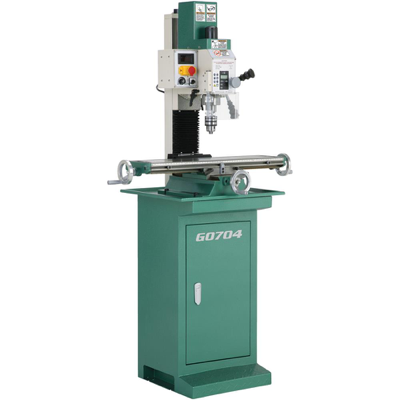
My goal with the machine is to be able to fabricate complex brackets out of (up to ) 1/4" Al plate. I thought about a real CNC mill, but was not willing to invest the time or cash at this point for a big machine. Turns out that was probably a good idea. This is a neat machine, but it may fall short of my goal. Still, it is a great way to learn CNC without a massive investment and to figure out a tool flow and develop experience that would be far more expensive to do with a bigger machine. I will ultimately end up probably with a CNC version of the Grizzly G0704, but that is a longer term thing.
Here is my own modified end product:

Modifications include:
1) Longer X and Y travel by 50% (up to 750mm from 500mm) doubling work surface area
2) Stiffening Y travel with mid-span brackets
3) Stiffening X by bracing dual extrusions together. Reduces torsional twist.
4) NEMA 24 motor upgrades on X and Y axes
6) Dewalt DW660 router for cutting. This thing is a beast. Very, very loud, though.
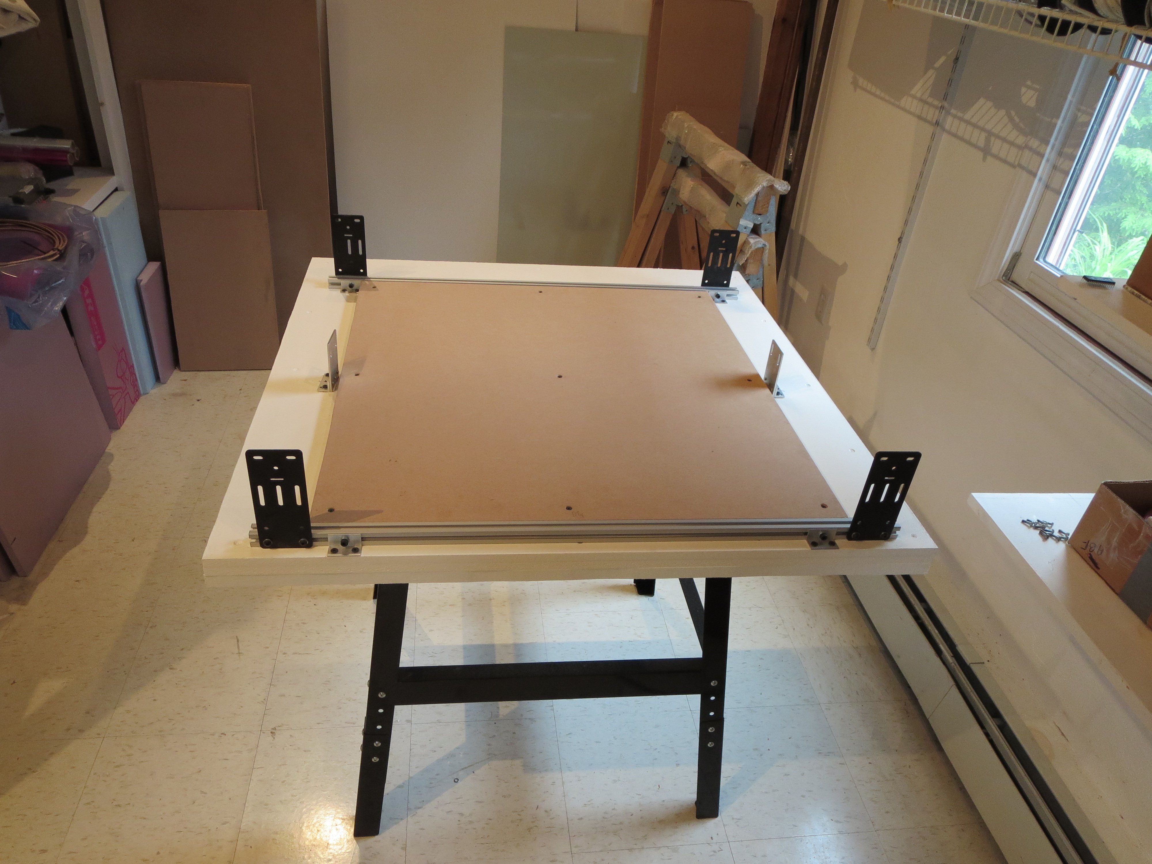
The table is a Harbor Freight $29 tool table. I buy less and less stuff from HF because of their marginal quality, but sometime they have just the thing. The base is layered MDF up to 1.75" think. The sheets are screwed and glued, but prior to that I shimmed them the best I could for flatness. The wasteboard is 0.75" thick.
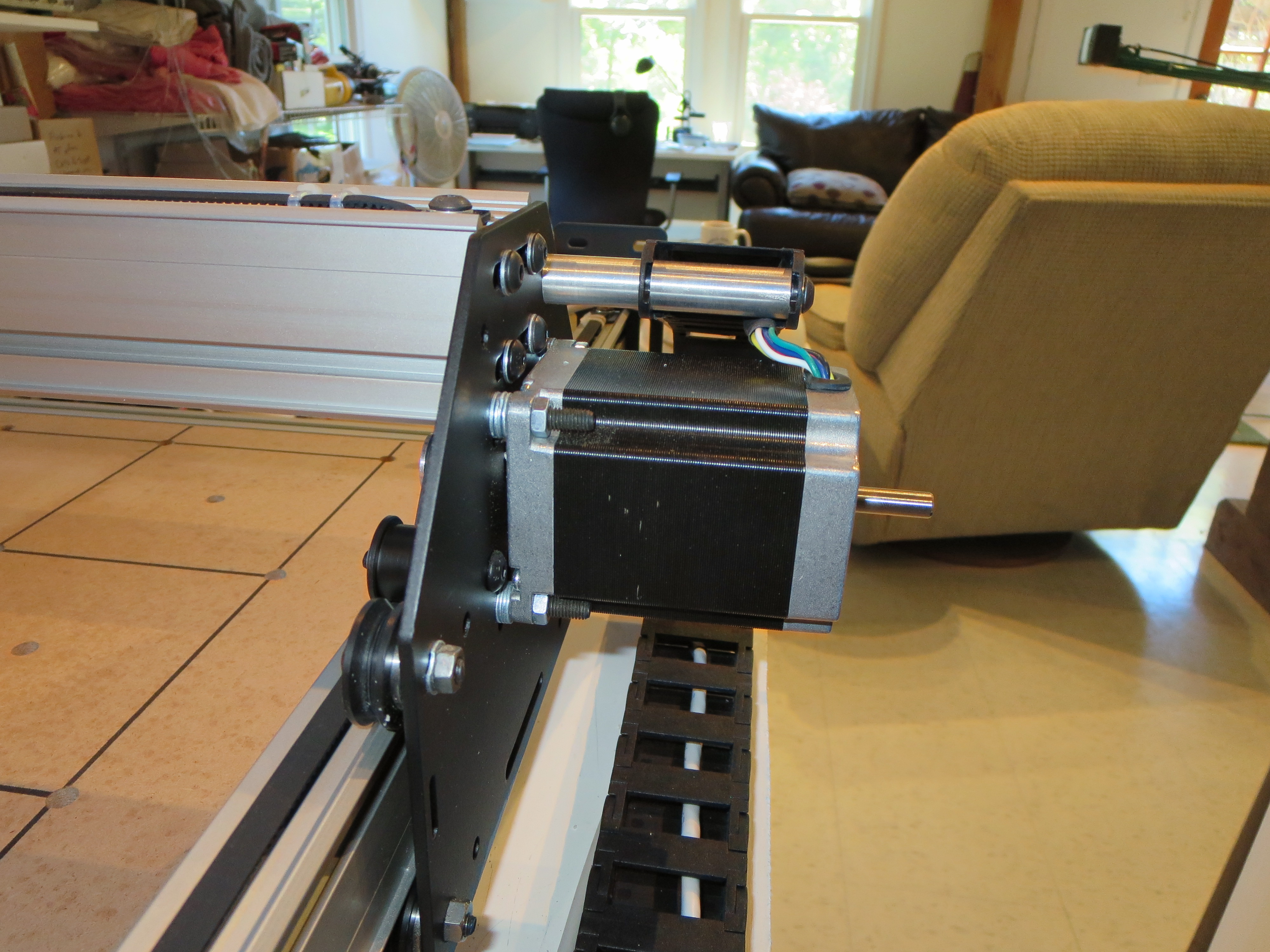
The Y-axis motors are NEMA 24 upgrades. a little shimming and careful attention to build order in order to fit it all together. Some quick lathed mounts for the drag chain.
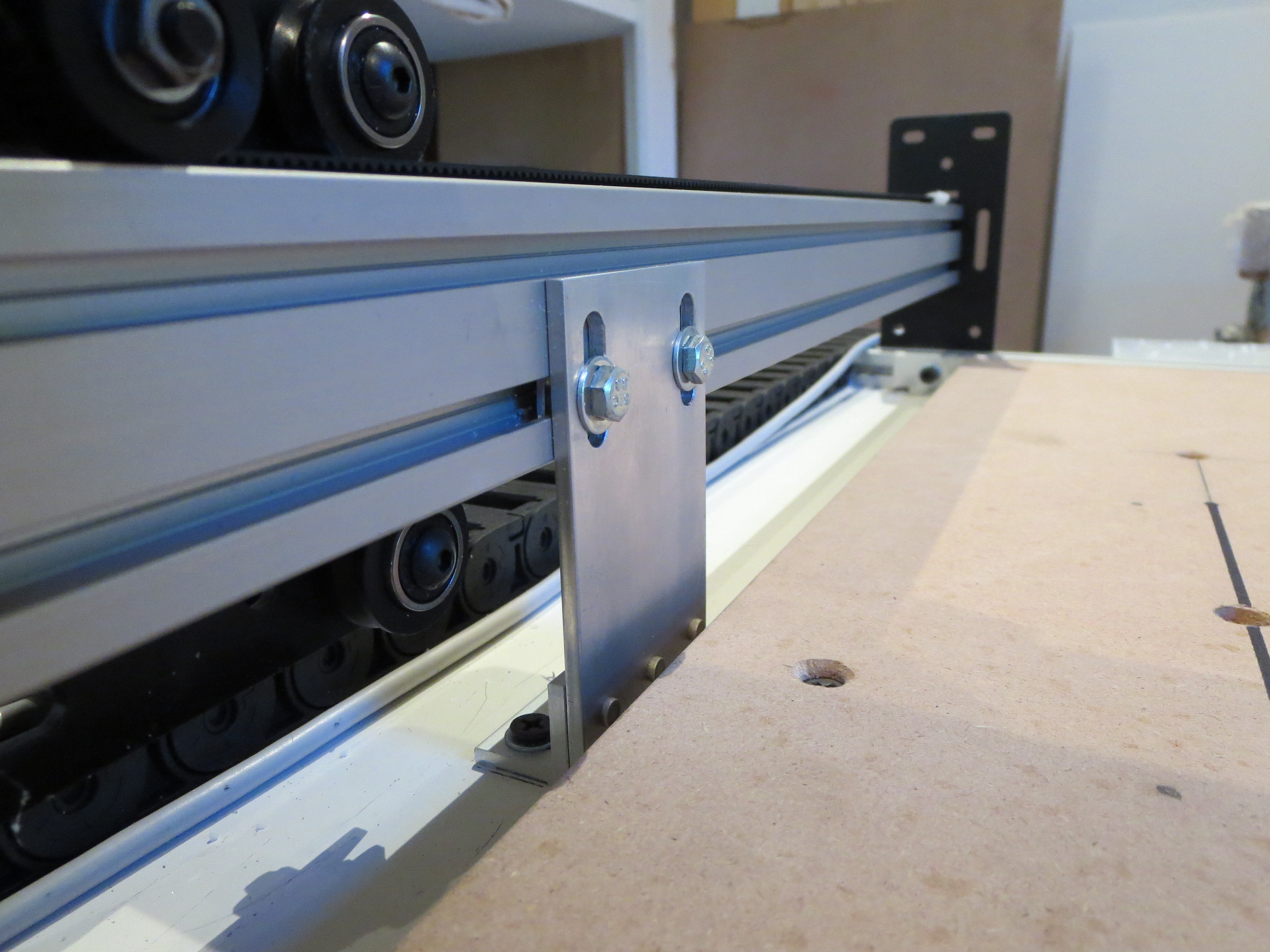 Whipped up a couple of braces for Y-axis support. Simple angle and plate machined up on my mill. Riveted with aircraft project leftovers. Nice to have the tools and materials at hand. The longer Y-Axis needs support in the middle and this also keeps the fore and aft direction from flexing.
 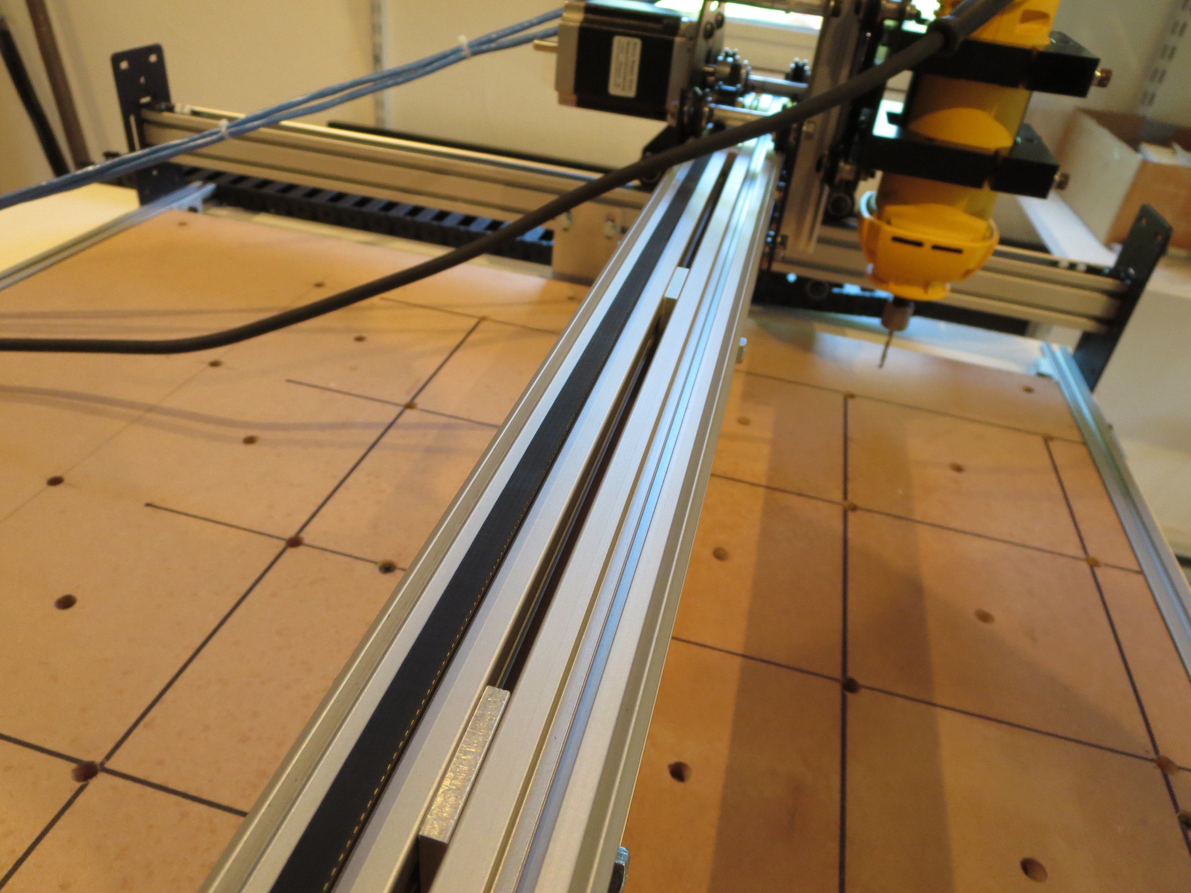 The stock configuration only has the pair of extrusions only attached at the ends. To keep the extrusions from flexing relative to each other, I first built up the carriage, fitted it, and measured and fabricated proper thickness shims to affix them together. This really stiffened up the carriage in the vertical dimension.
It is important to build it up before measuring for the shims as the width can't be determined accurately until the thing is fit together to find the "natural" width of the carriage rollers.
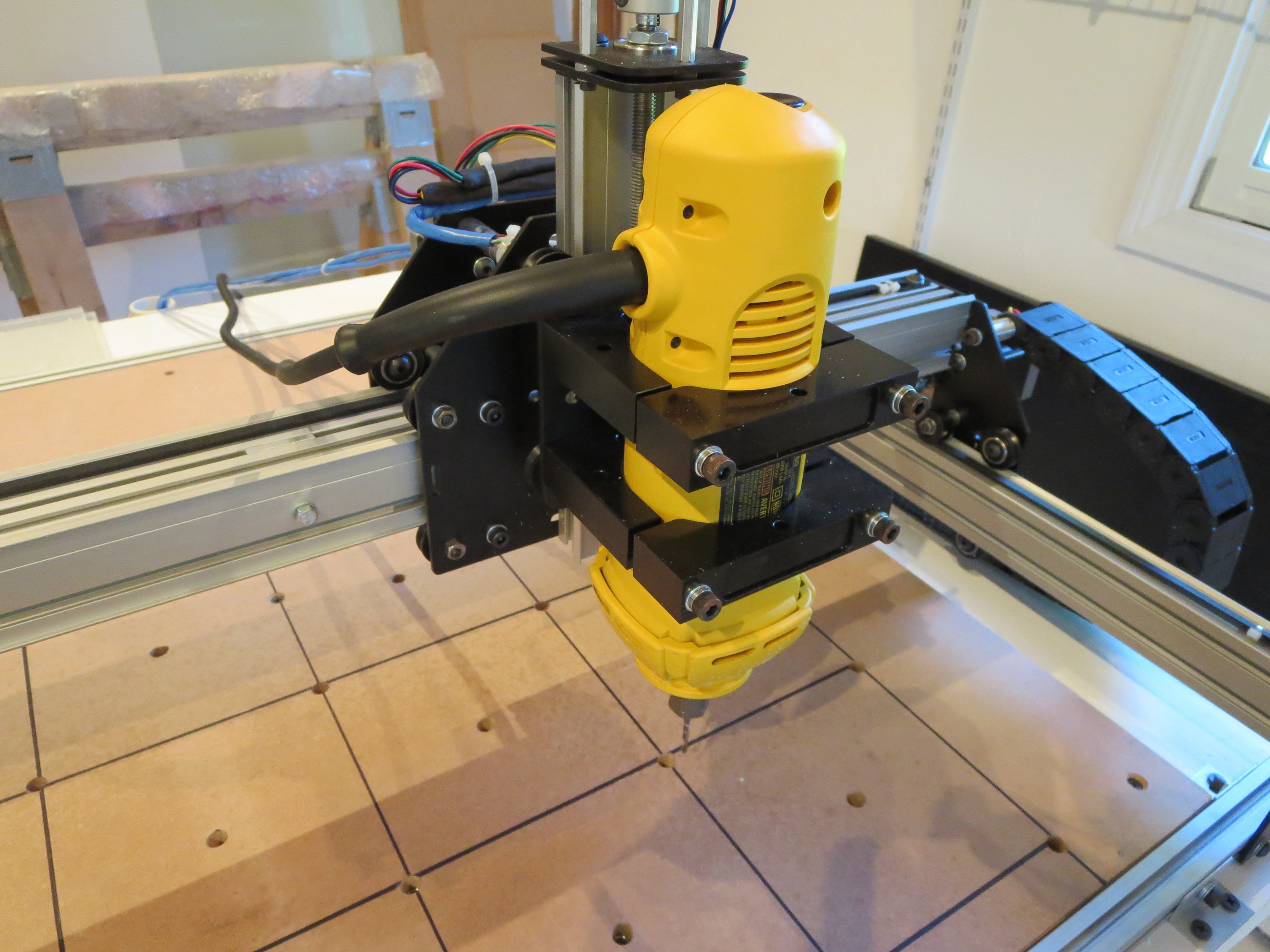
The DW660 router is much heavier than the stock spindle and needs good bracing. The wires from the X-axis and router will be dressed better when I get a smaller drag chain. Works for now.
Electronics bolted to MDF plate in the back of the machine. Protected by the table top, so I didn't feel the need to make a full case.
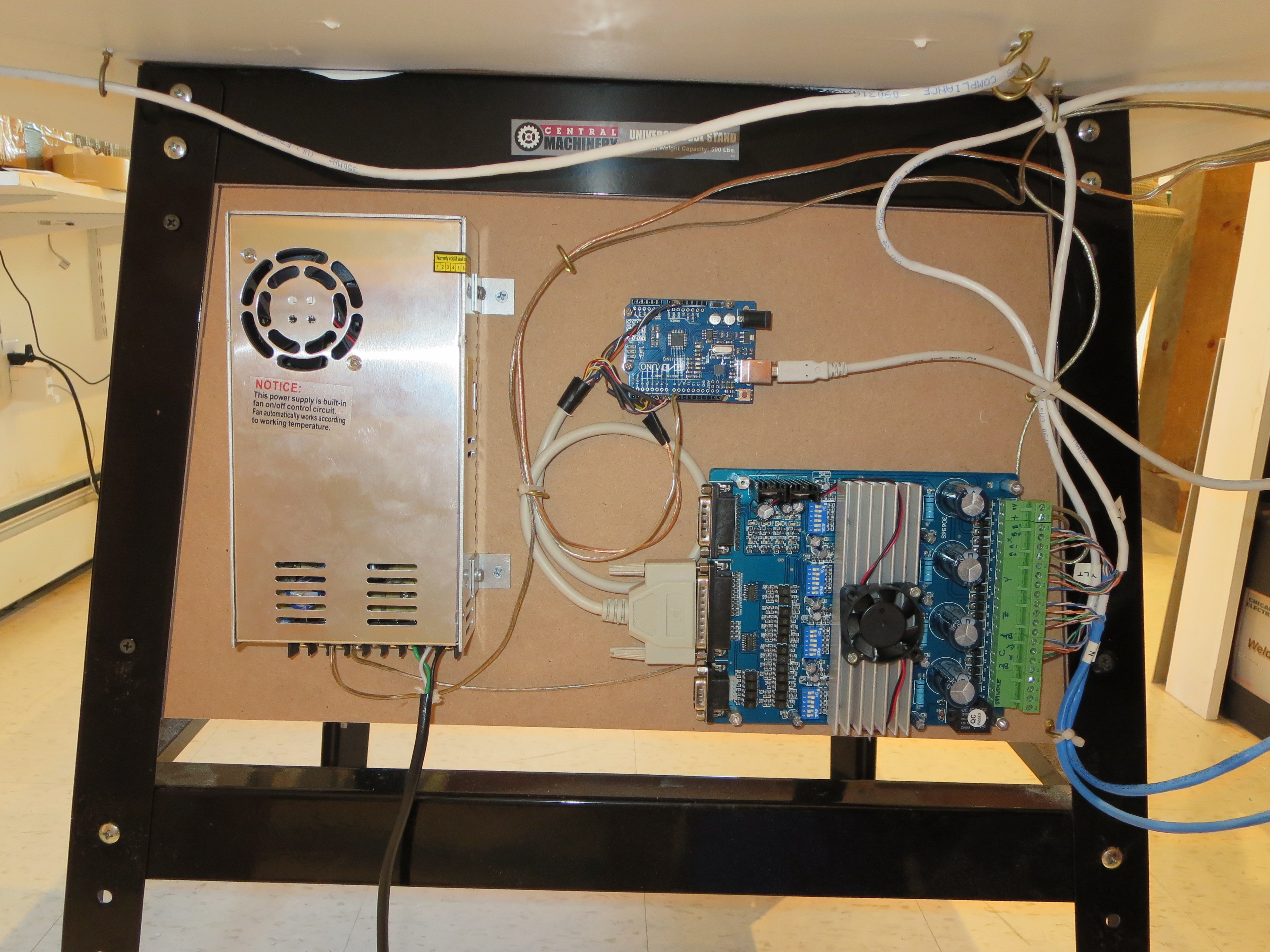
The motors and controller were purchased off ebay for about $200 from wantaimotor.com. Wow. Lots of capability for short money. It all worked, but was not at ALL documented and the limited docs that were provided were WRONG. A lot of web searching and reverse engineering needed to figure out pinouts, voltage levels, and controls. The controller is an Arduio UNO ($10 on ebay) running GRBL. Doesn't get much cheaper for CNC control.
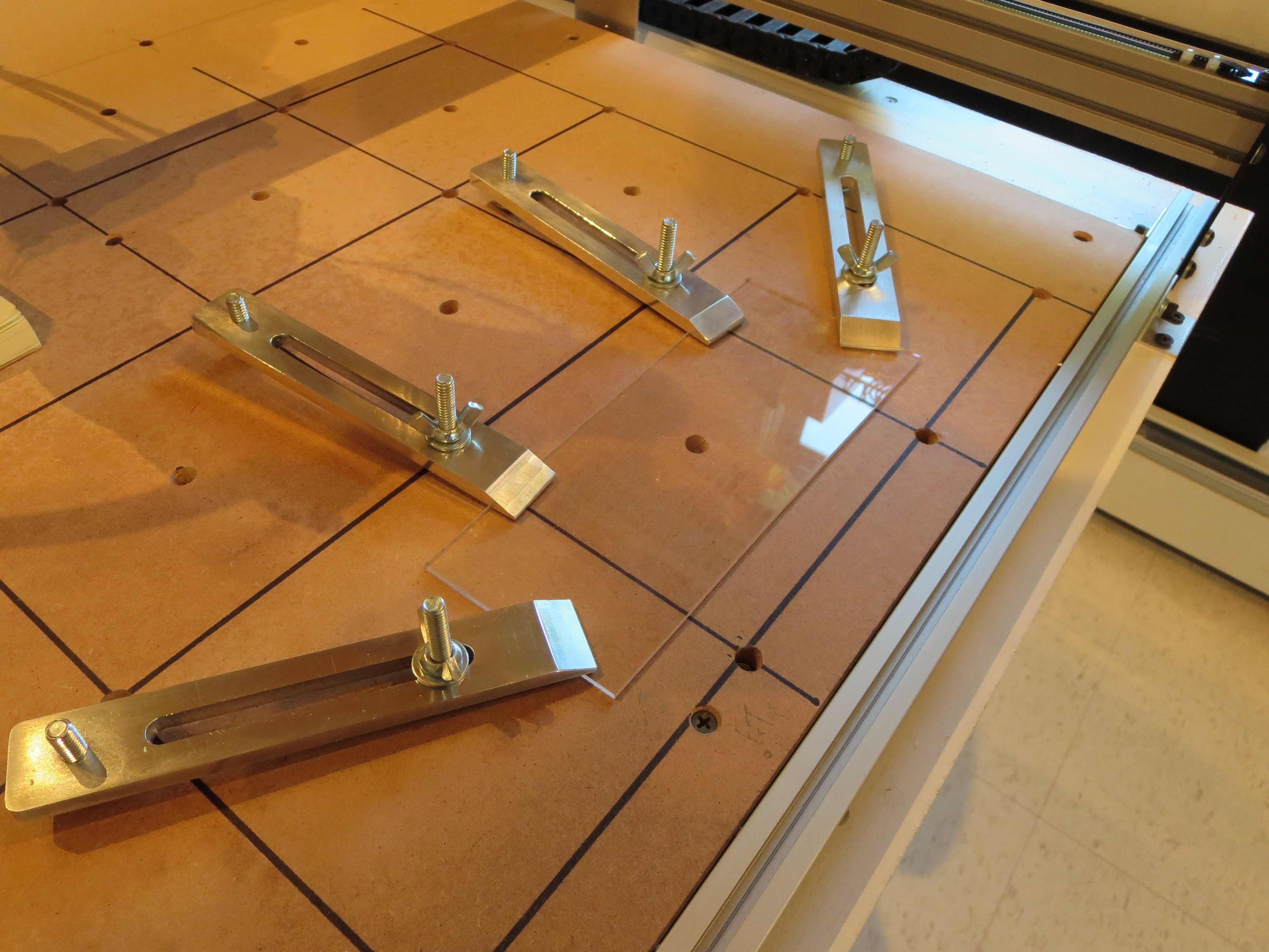 Made some hold-down brackets on the mill. The washboard has an array of T-Nuts installed flush from the bottom. Screw the threaded rod from the top into the wastboard, slip over the hold-down, adjust the carriage bolts for the right angle, and then spin the wing nuts to tighten. Simple and effective.
My tool flow is:
Spaceclaim (running under Windows VM on my MAC) - 3D and 2D modeling of parts and brackets. Export is DXF (2D) or STL (3D)
or
Adobe Illustrator (running OS-X on MAC ) for art drawings and 2-D text for engraving. Export is DXF
CAMBAM (running on Windows-VM on MAC)for tool path generation. http://www.cambam.info
Universal G-Code sender (running OS-X on MAC) for controlling the machine (free)
So all-in I had to buy CAMBAM for about $180. The rest was free or something I had already.
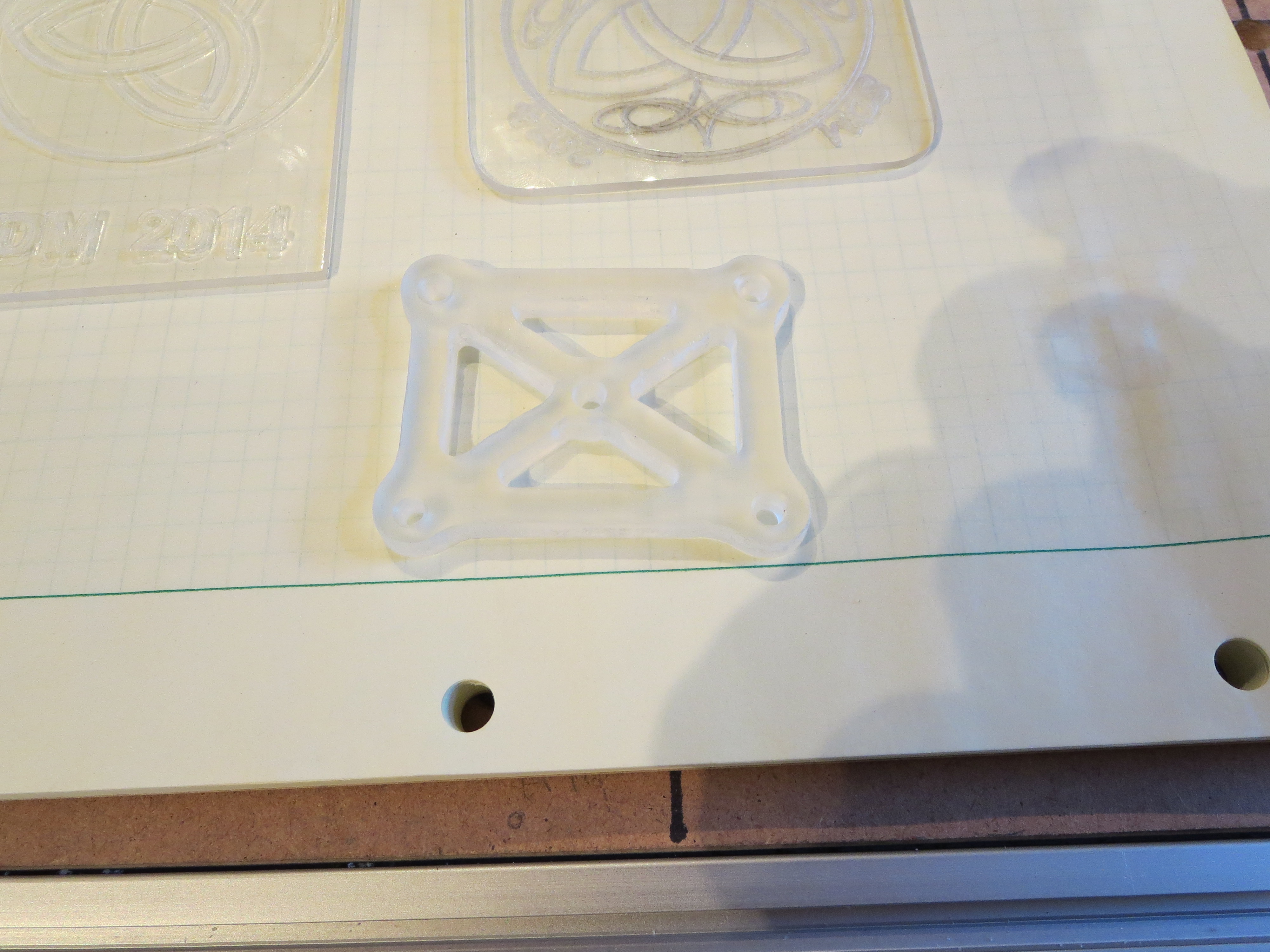
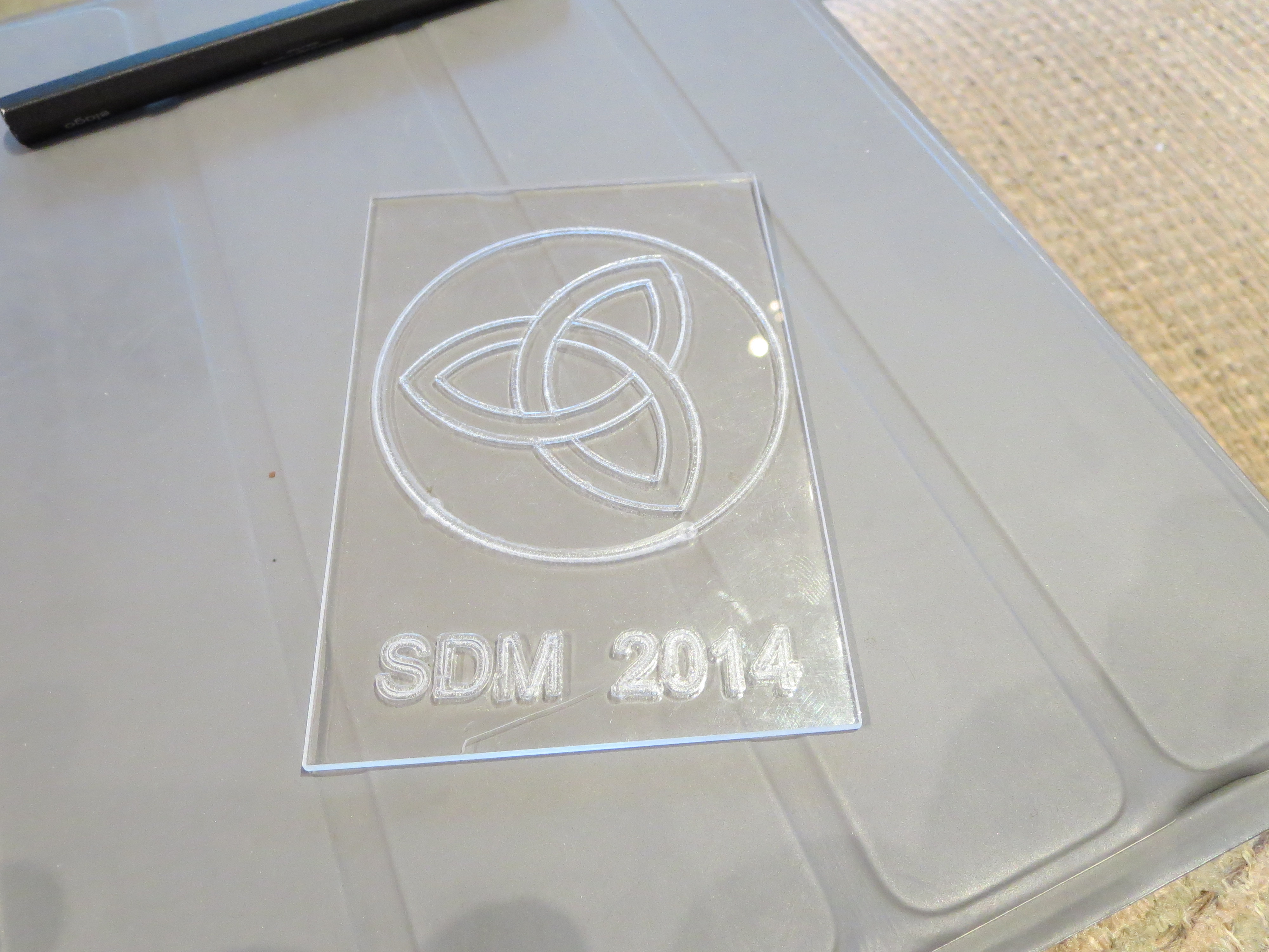
Here are some early examples in some plexi scraps I had lying around. Obviously I have to work on tooling and feeds for better results. Cutting plexi is weird in that you have to be careful. If you cut too fast it "fragments" at the cutter. Too slowly and the plexi melts and build up on the cutter, affecting the accuracy of the line.
Conclusions:
For engraving this will be great. For milling soft stuff it's probably fine - haven't done much there yet. For aluminum it is weak. It is just not stiff or strong enough, even with my modifications, to accurately cut thicker plate. I will experiment with speeds and tooling to see if something acceptable can be determined.
The machine works great for what it is. I can see perhaps cutting outlines and lightening hold in brackets, then moving the piece to the mill for accurate cutting of holes. It is very satisfying to see it run repeatably and position accurately; hypnotic almost. I have learned a lot and when I do get to the construction of a man-sized mill it will go much more smoothly. I have purchased a 2W laser from ebay to try my hand at laser etching. That'll add a whole new level of danger to the shop.
My total investment is about $700 and a month and a half of weekend spare time. I think of it as a self-taught course in CNC machining. From that perspective it seems pretty cost effective. It's now just another tool in the shop. Like the Mill - it was a project that once done will become a very useful tool. Time to get back to the Helicycle.
Main Shaft Plug
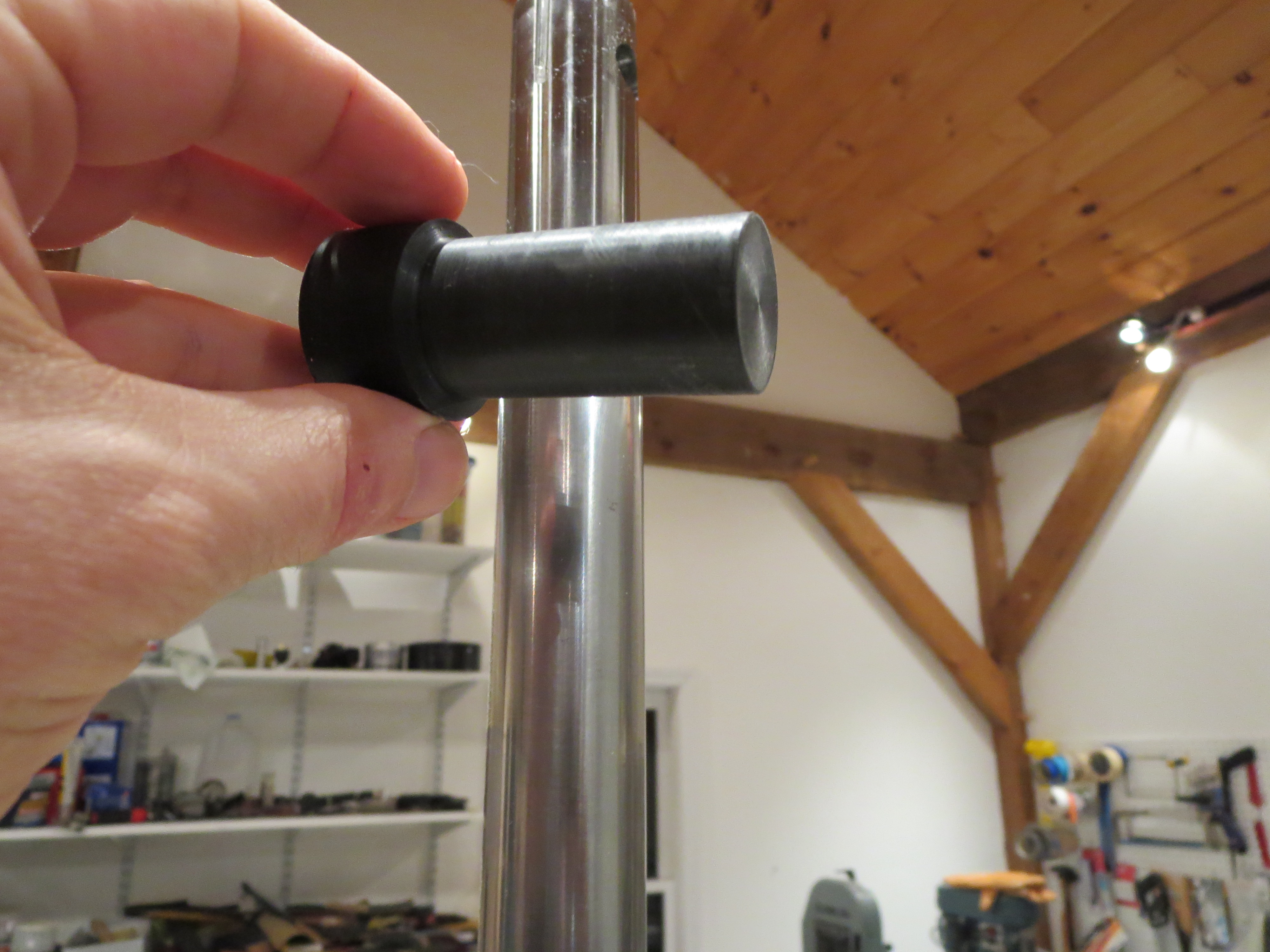
Well ahead of the transmission installation video in the rotor head video, BJ mentions how the main shaft should be plugged to keep out moisture. First up was to slather a goodly amount of Corrosion-X in the shaft after a few acetone swipes. Then I lathed up an ABS plug that was snug, but not even really "tap tight". Once parted the plug is only about an inch long.
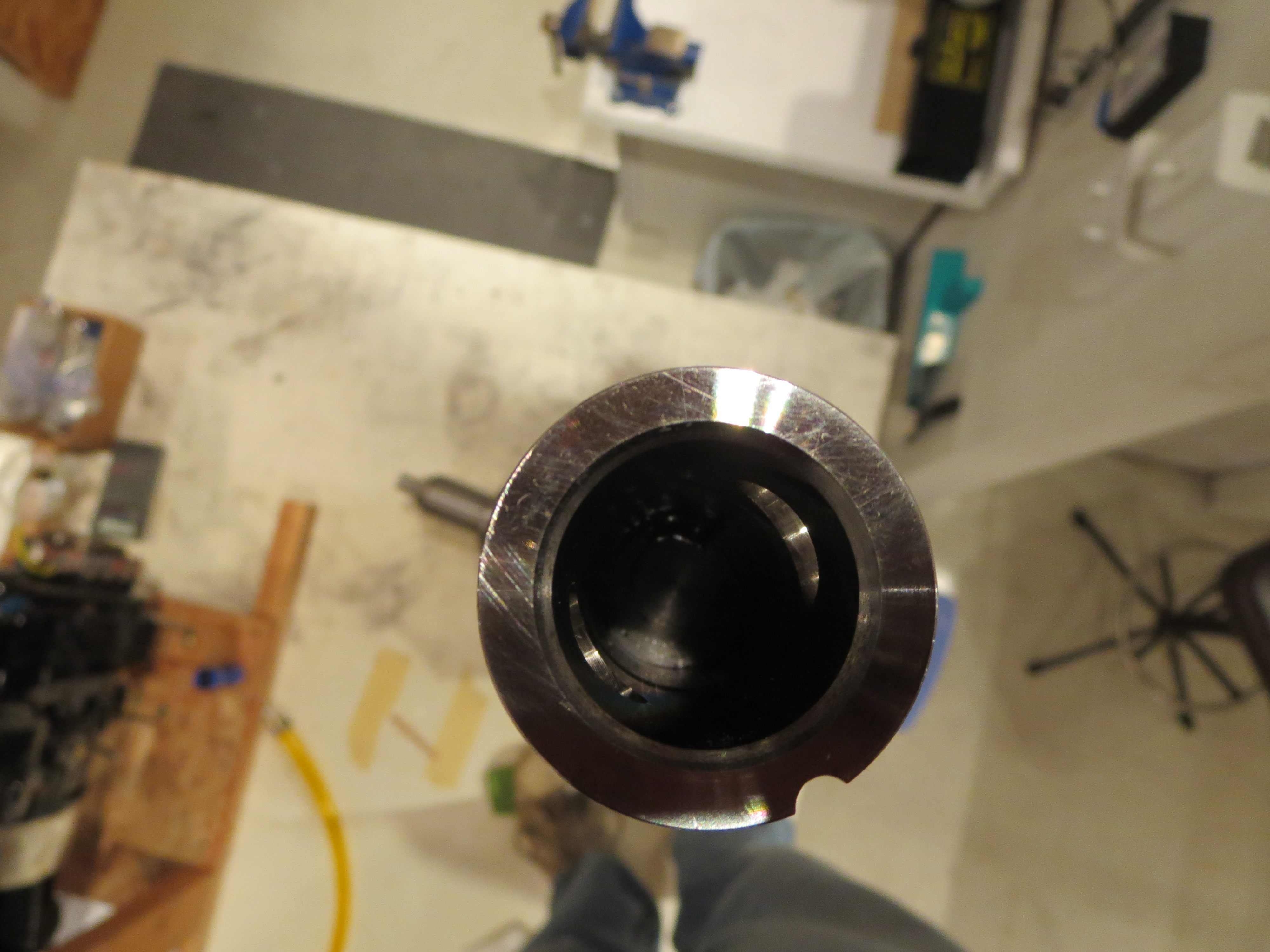
The plug was coated with 5-minute epoxy and slid down inside the tube. I measured the steel main drive plug that slides inside the shaft, then I pushed the moisture plug down plenty far enough to clear the plug when it is installed. While the epoxy was setting up I wiped and cleansed the inside of the tube above the plug with acetone to remove any trace of the epoxy so the drive plug will not be fouled when it is inserted.
The edges of the hole for the drive pin are sharp, sharp, sharp, and I cut the hell out of my finger while swabbing out epoxy. Nice mixture of acetone and epoxy now coursing through my bloodstream. About every two weeks I will cut a finger, grind myself or otherwise accumulate minor scar tissue on this project.
Lower Tank Closeup
I dried out the lower tanks and closed up the access hatches. Of course I discovered that there was an interference between the retention ring then the inner part of the nipple fitting inside the tank on the left side where things are pretty tight. Fishing the ring in the tank without dropping it is bad enough, but then fishing it back out is a double pain.
Once sealed, the tanks were pressurized with an extremely sophisticated, NASA inspired pneumatic pressure source. Then all the joints and interfaces were brushed with soapy water to check for bubbles. No bubbles.
With this last set of tasks on the lower tanks, they are ready to install. They can't be final installed, though, until the main transmission is installed. That is now the focus. It has already been fitted once and aligned, so all that's left is to reinstall the plumbing and some final surface prep with Evershield.
Surprisingly those balloons were pretty good. They stayed inflated for 6 days with only the slightest shrinkage. Usually party balloons self-deflate after a day or two.
Rebalancing the Pulley
The locations that needed milling were on the side opposite the holes that had been drilled. This kind of makes sense if the holes were drilled to compensate for differences in the mass of the bosses that were milled off.
Lower Tank Final Prep
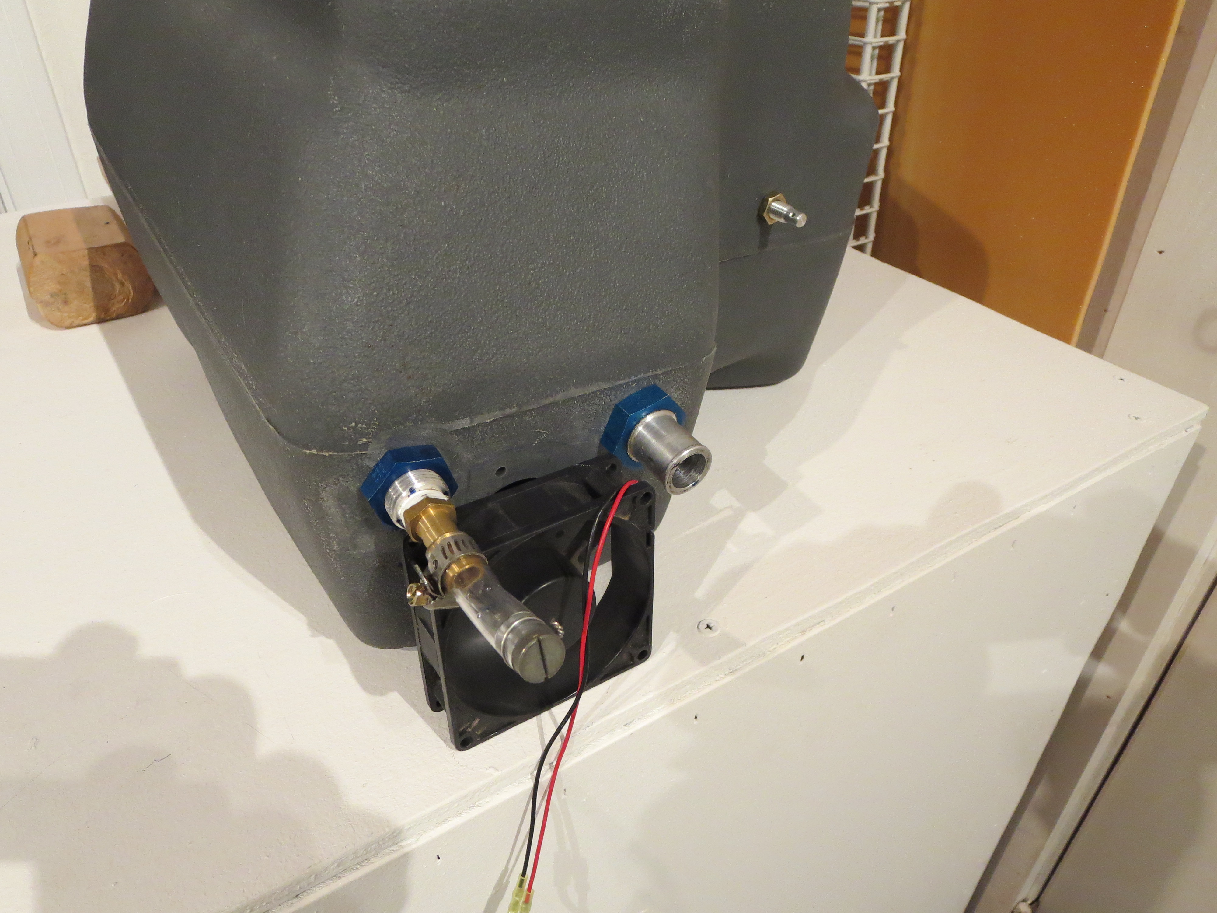
I blew all the crap out of the lower tanks and gave them a good rinse. I did not want to do the final rinse with gasoline as BJ suggests since all my work is inside my shop and it would get stunk up. That left the problem of drying them out after a rinse. Turns out that a little muffin fan blowing in the large hole and venting out through the upper hose nipple was enough airflow that after a couple of hours they were bone dry inside. Excellent. Next up a pressure test.
Transmission Final Prep
Now I have to dig out my references on how to re-install the plumbing.
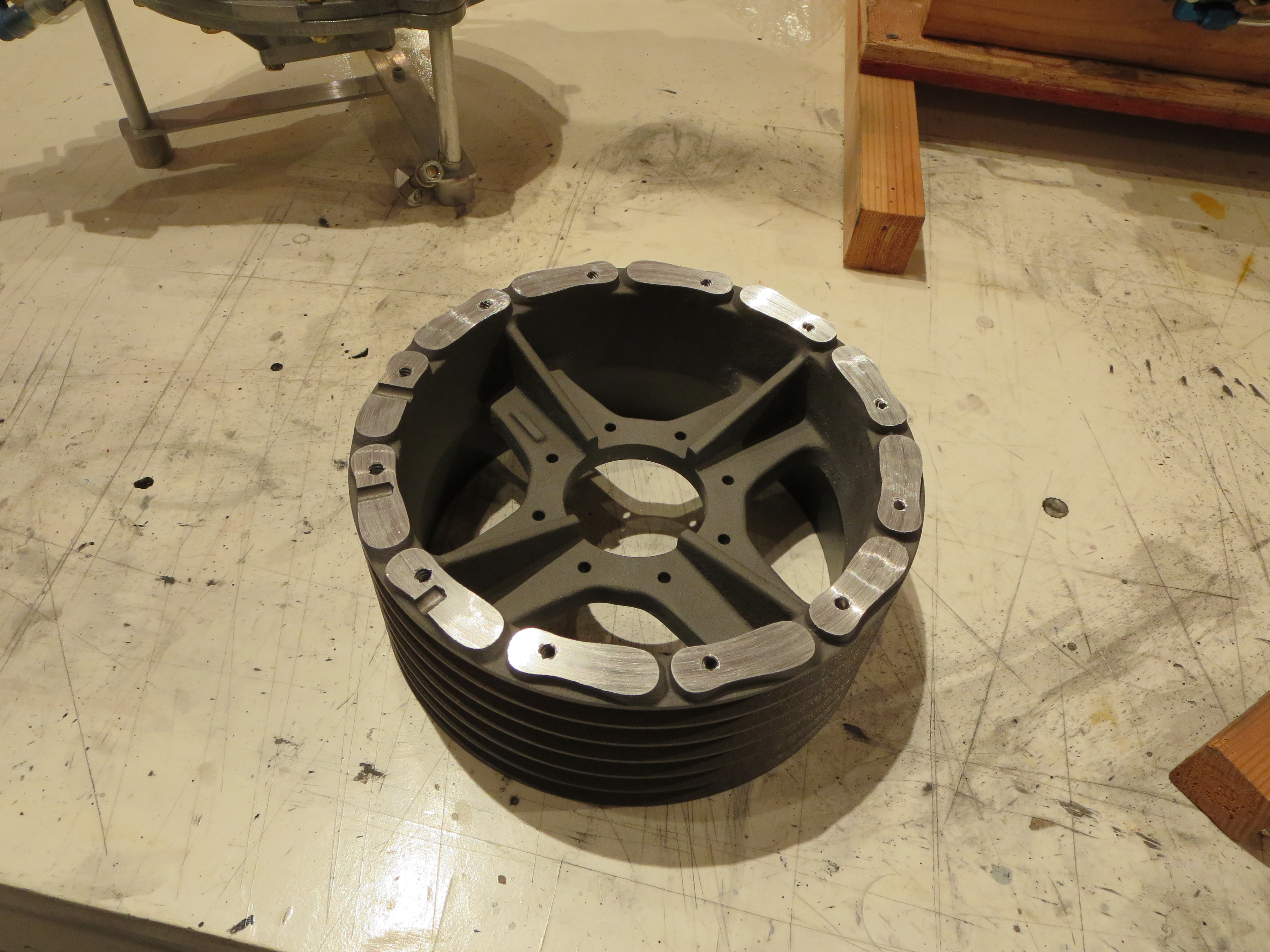
Since I am not planning on installing the fiberglass fan blades the bosses cast onto the pulley are just dead weight, so I chucked up the main pulley in my lathe and shaved them down. Any extra room in the pulley bay will be welcome I am sure. I left a little meat on the pads from the bosses to give me something to mill off in case there is some balancing to be done. You can see the remains of a couple of leftover holes that must have been drilled for balancing purposes back at the factory. I will admit that I did not notice those balancing holes until I started cutting and now will have to rig some sort of jig to allow for redoing the balance.
This is the largest thing I have ever worked with in my lathe and it was clearly operating at capacity.
Top Tank Final Mount
Double nuts, Loctite, and Torque Seal.
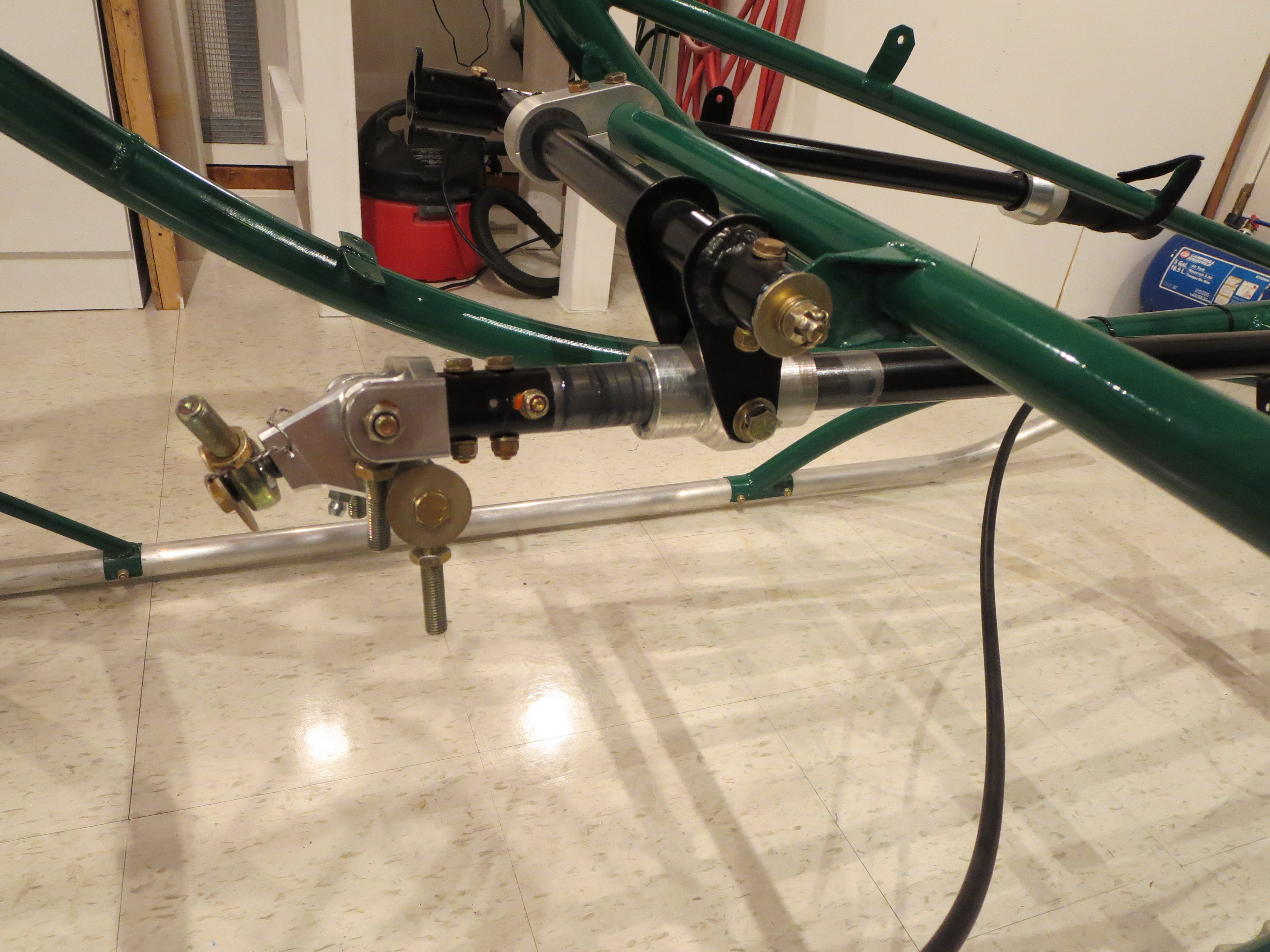
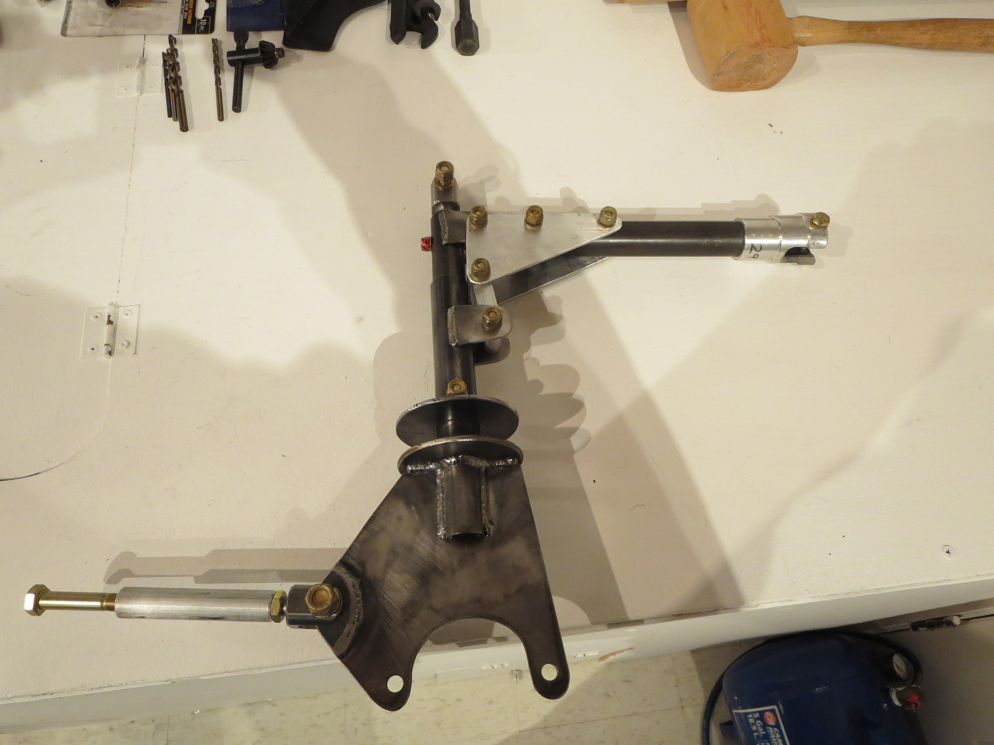
Clutch Final Assembled
I used the Hap Miller compression disk instead of the stock rubber biscuit. Looks nicer and should be more stable. The bolts holding the angle plates are only bolted through the tubes, so the bolts can't really be torqued to spec (60 in-lb) without deforming the tubes, so torque was lowered a bit. All bolts were Loctited and all sliding surfaces were greased prior to final assembly.
Controls Installed
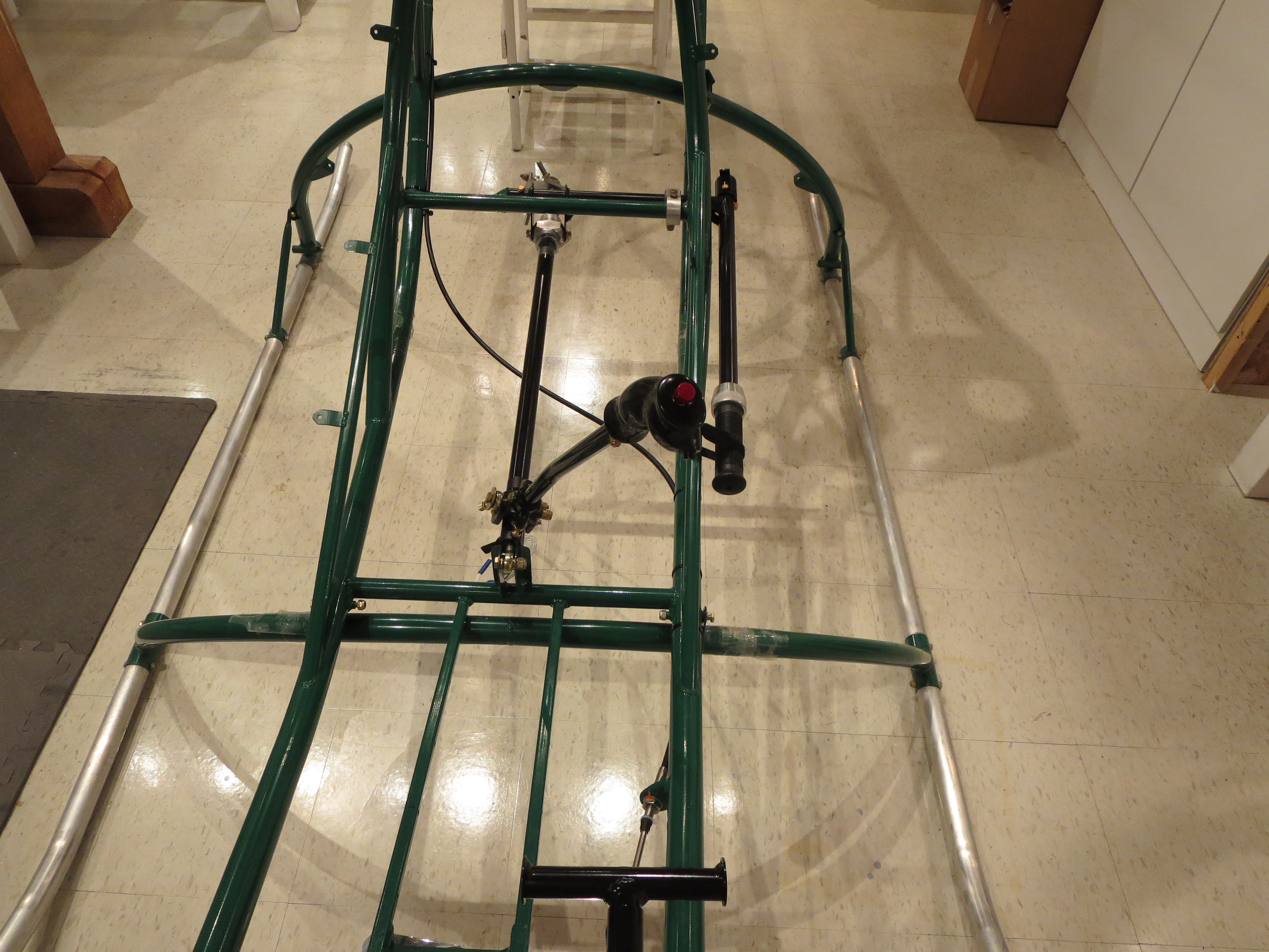
Everything is torqued and safety wired. I put a dot of torque seal on the nuts after final installation. Since all the pieces had been pre-fit, it was very straightforward. The only annoyance was that one of the Grade8 bolts I had purchased pre-drilled really wasn't drilled all the way through. It demonstrated that the Loctite sets up very quickly. The portion in the threads was already gummy after only an hour or so after installation.
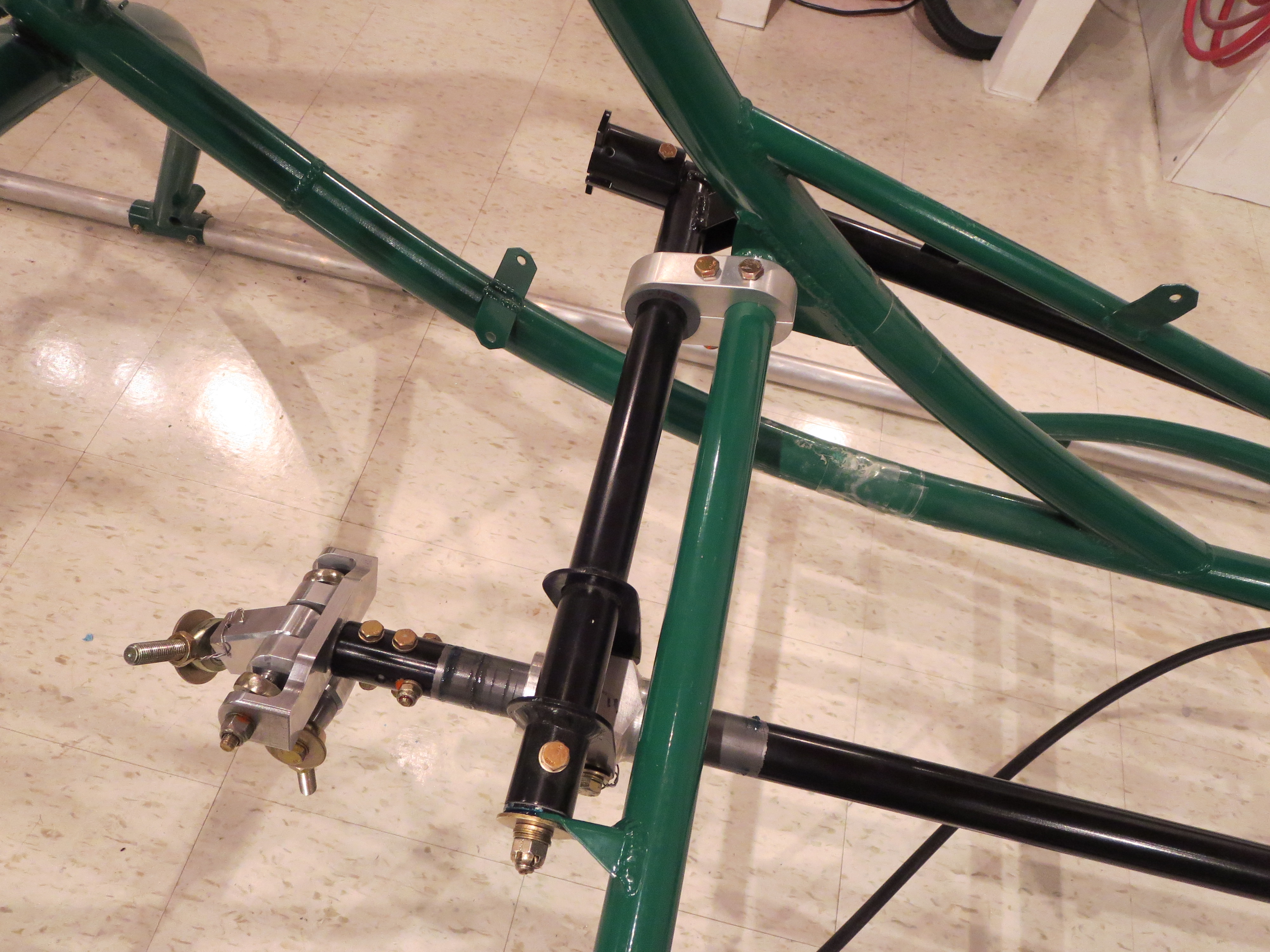
The control stick has almost no resistance fore and aft due to the bearings in the stick, but a slight amount in the left right since it is turning the cyclic shaft in the slider. It;s all greased well, and there is no breakout force, per se. We'll see how it all feels when the rest of the control arms and fittings are installed.
Mixer Assembled
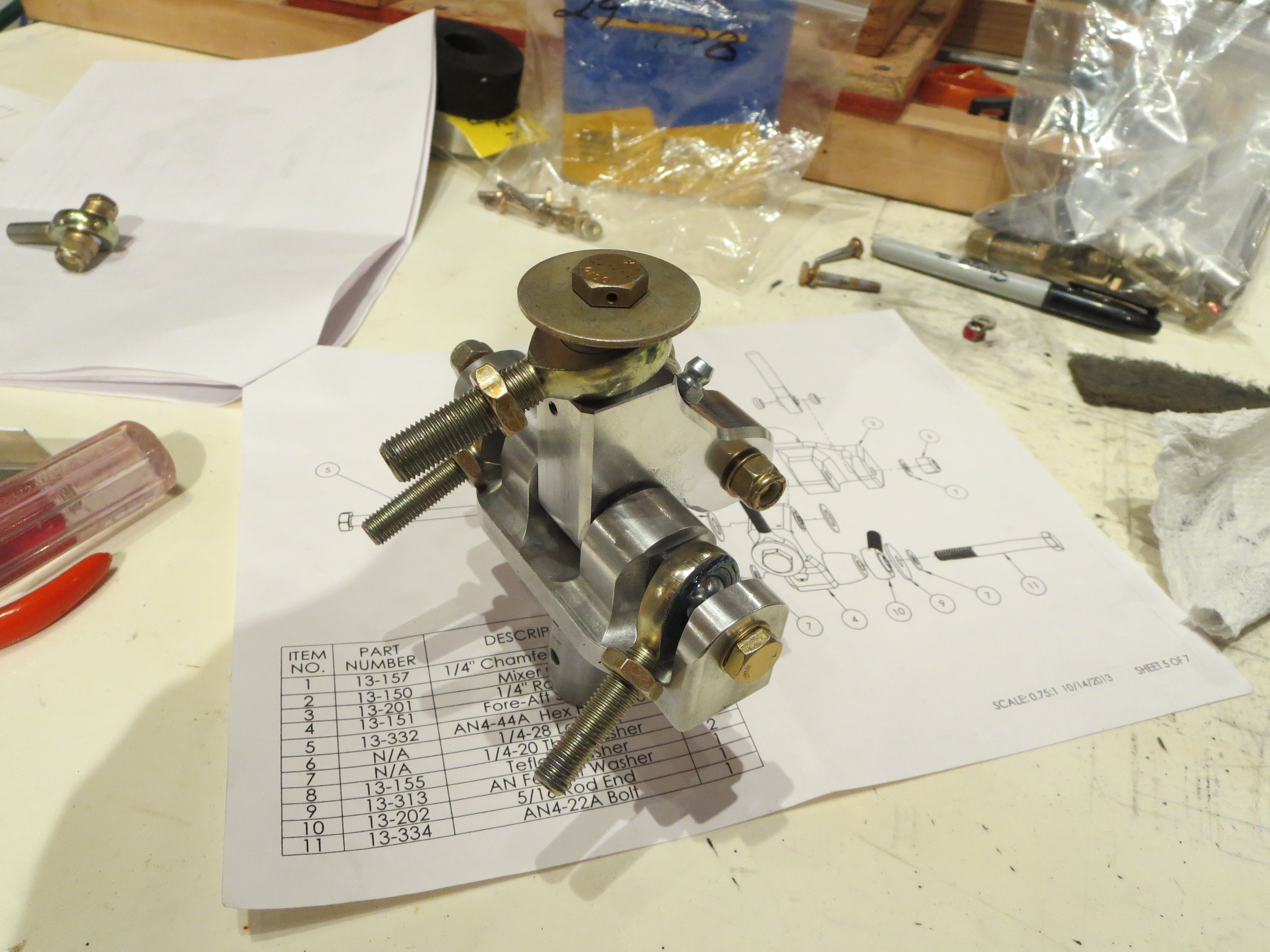
This is so much nicer than the original item. It looks and feels like a quality item.
Clutch Pre-Assembly
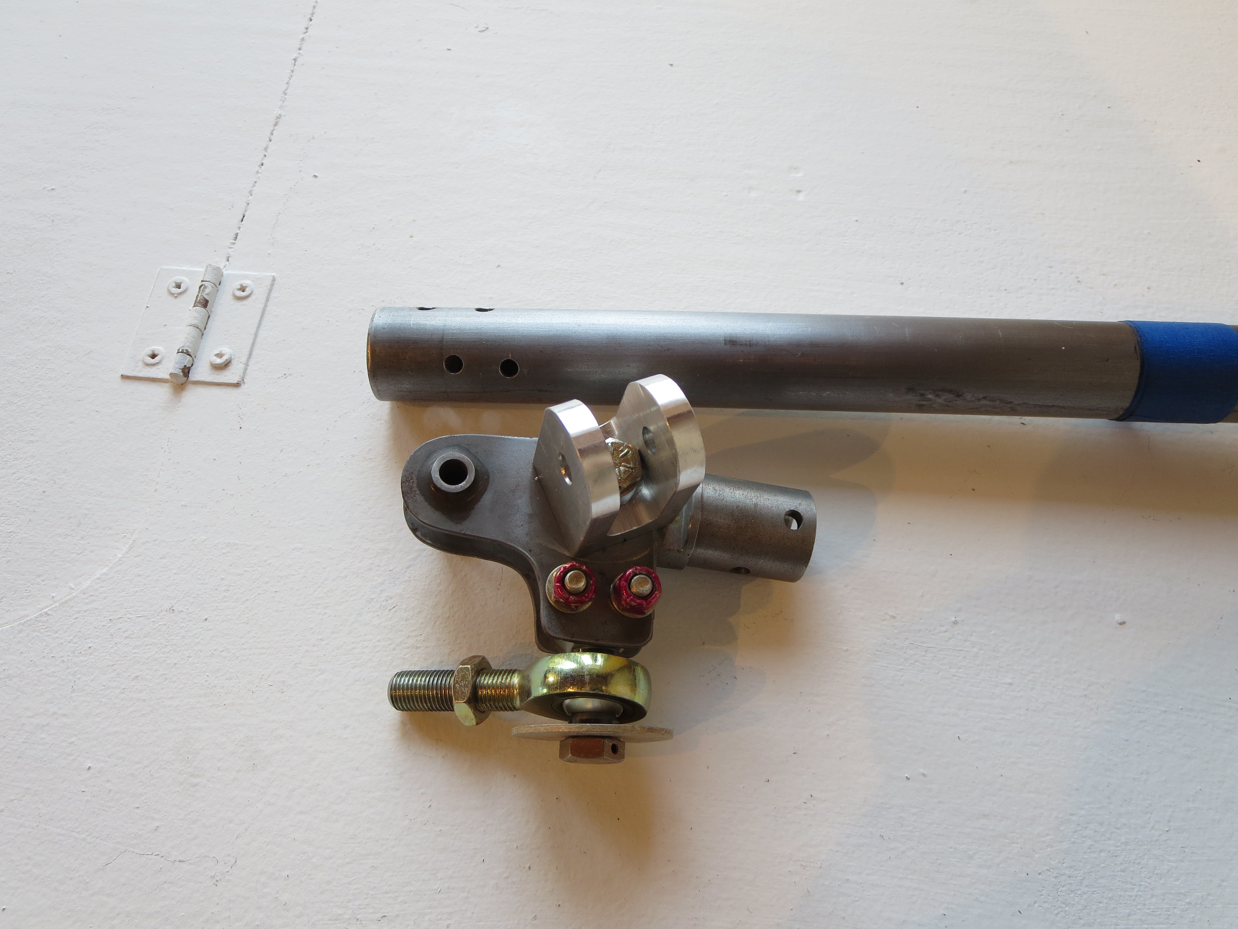
Next up is drilling the side plates to the clutch lever arm. I made use of my jig plates (from the cyclic tube mixer mount operation) to get a perfect alignment between the bolts and the holes for the plates.
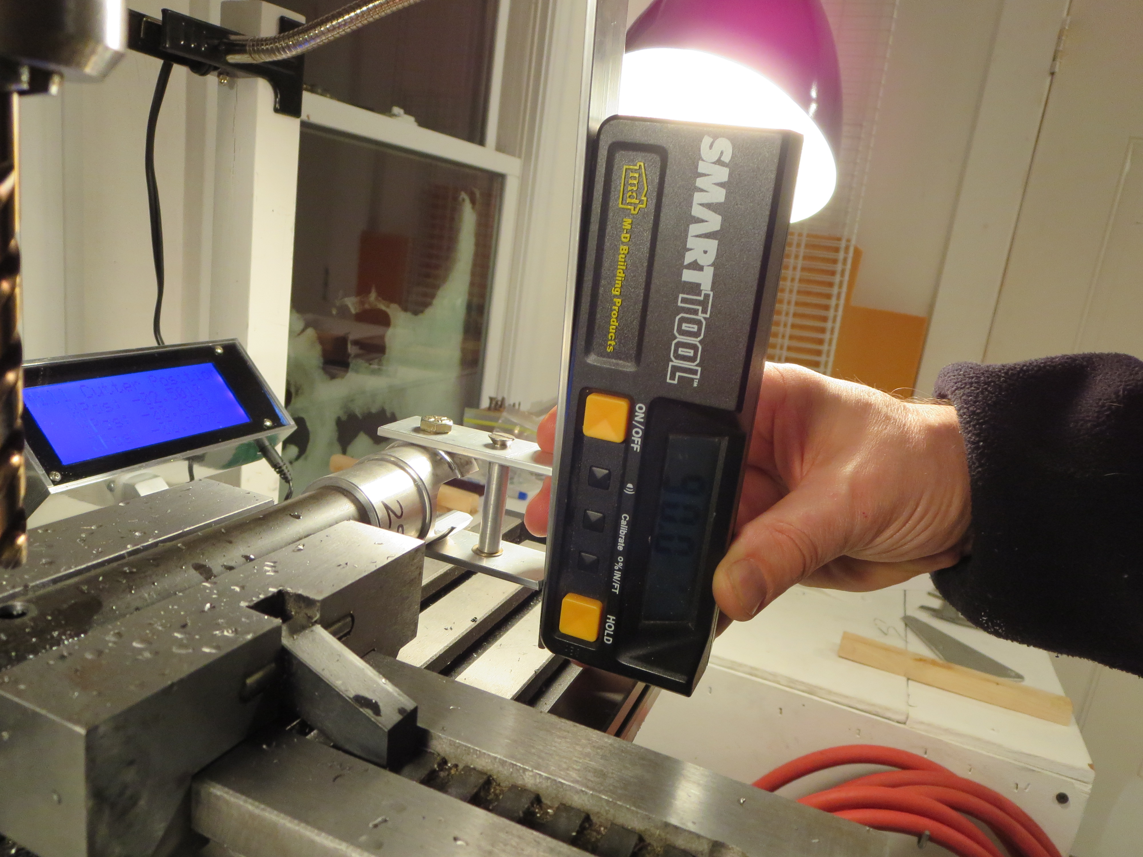
Jig plates repurposed and alignment exact. It pays to make sure that mill is perfectly level and mill head is trammed. Then everything can be referenced to 0.0 degrees or 90.0 degrees.
It seems like a pain to make little jig thingies for a single operation, but I usually can find a secondary purpose for them which make the time spent much more worthwhile.
Complete clutch assembly pre-fitted (except rubber parts and bearing). Now I just have to tidy up the steel parts (they picked up some scale having sat for so long), prime, and paint. With the precision of the mill, and no broken drill bits, the pieces just fall together, snug and true. The clutch is a very simple assembly project.
Mixer Refit
The original mixer (partially disassembled) looks fairly primitive next to the nicely CNC machined parts of the new one. I was never a huge fan of the single bolt in the center holding the "wings" together.
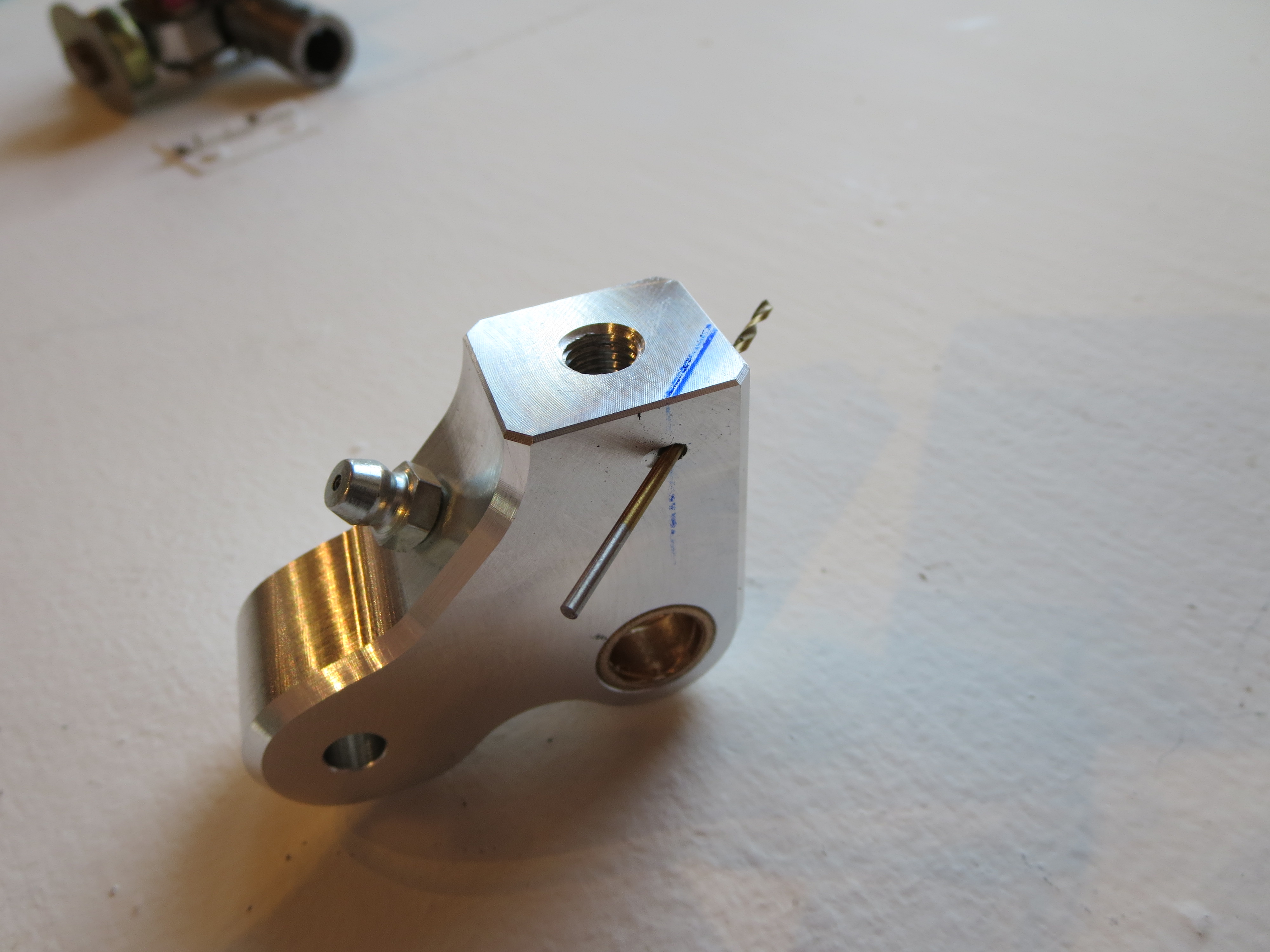
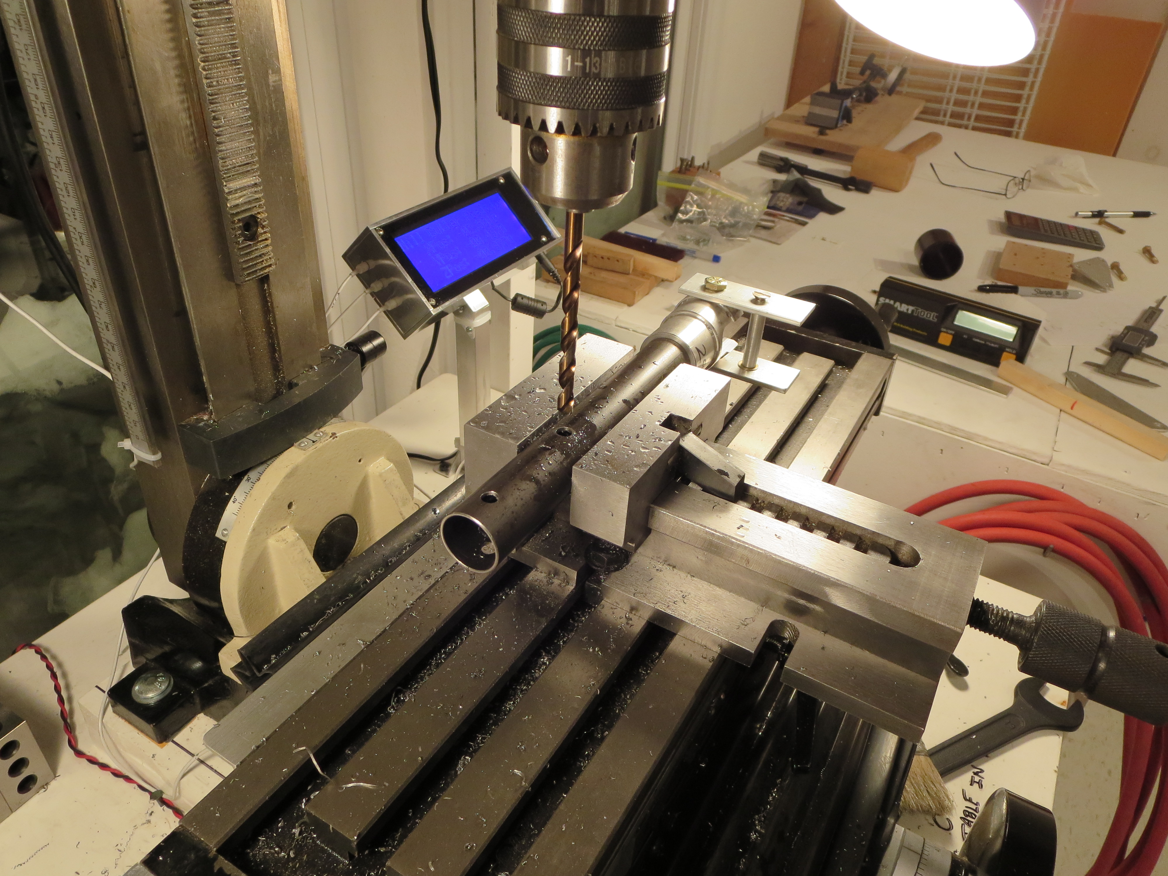
Start by drilling the hole for the safety wire on the fore/aft arm. On the collective slider I did them "free-hand". On this piece and with the mill and a couple of holding blocks this is achieved in very short order and with less hand wringing. Center punch the start location. Use a center drill to provide a "divot" so the real drill doesn't wander and away we go.
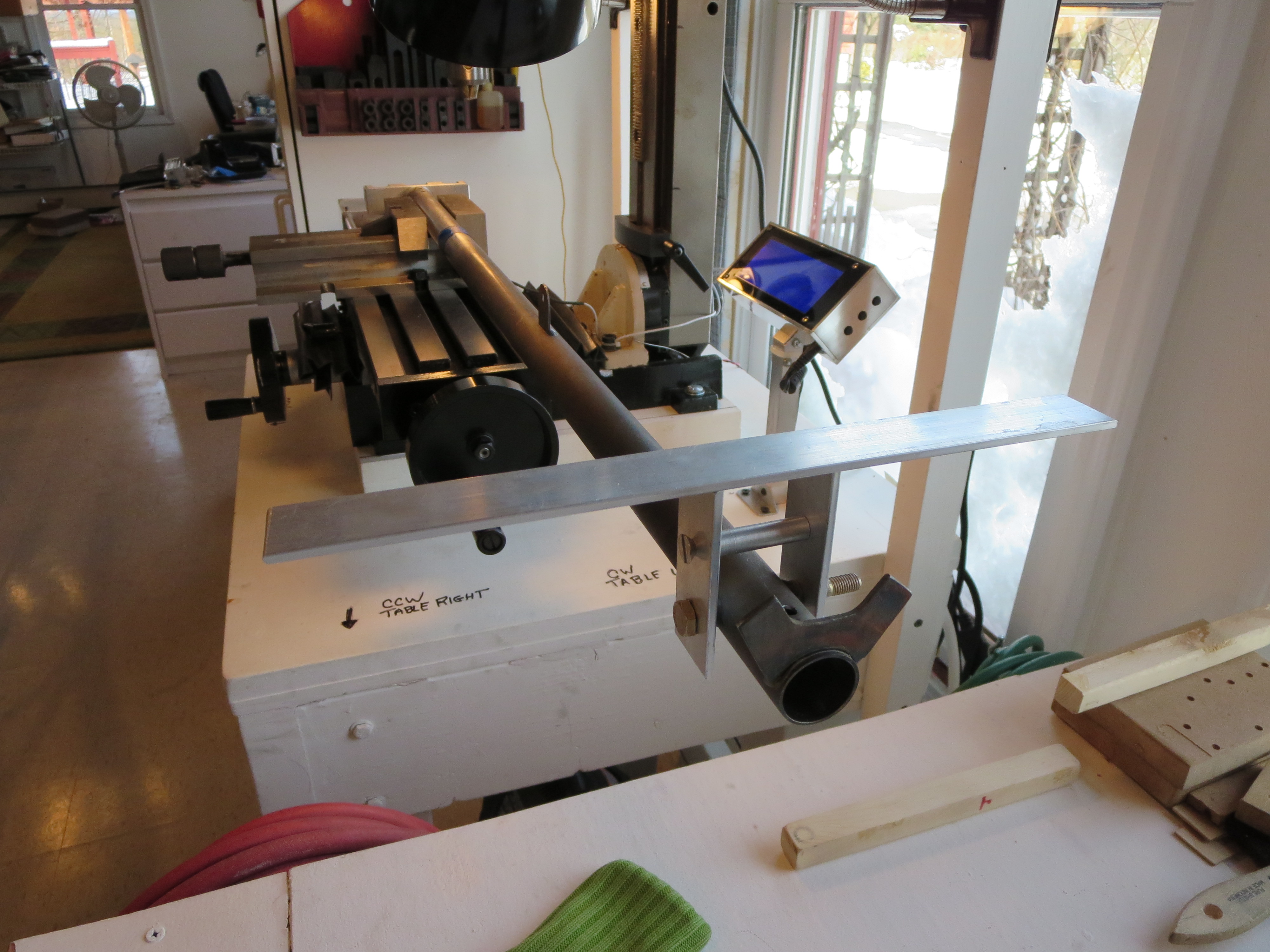
To precisely align the mixer with the control stick I made a little jig. Those two aluminum plates were machined in a stack, so they exactly match. The holes were drilled and the top edge machined to form a precise reference edge/plane. Both plates are exactly the same dimensionally. Then I made a little spacer on the lathe the exact same width as the cyclic bolt tube. Bolt 'em together and place a bar across the reference edges. My digital level was then used to get the angle between the reference and the bottom of the mixer block to exactly 0.0degrees.
Of course right when I was feeling smug and competent, BAM. The drill bit snapped off on the first hole. Crap! About half an inch into the hole. Of course you can't drill into a drill bit, so instead of boogering things up I stopped and stared at it for a while.
First I tried digging the broken bit out with a pick and needle nose pliers - no joy. Then I milled the hole slightly and the broken end of the drill bit. At least at that point I could remove the mixer block.
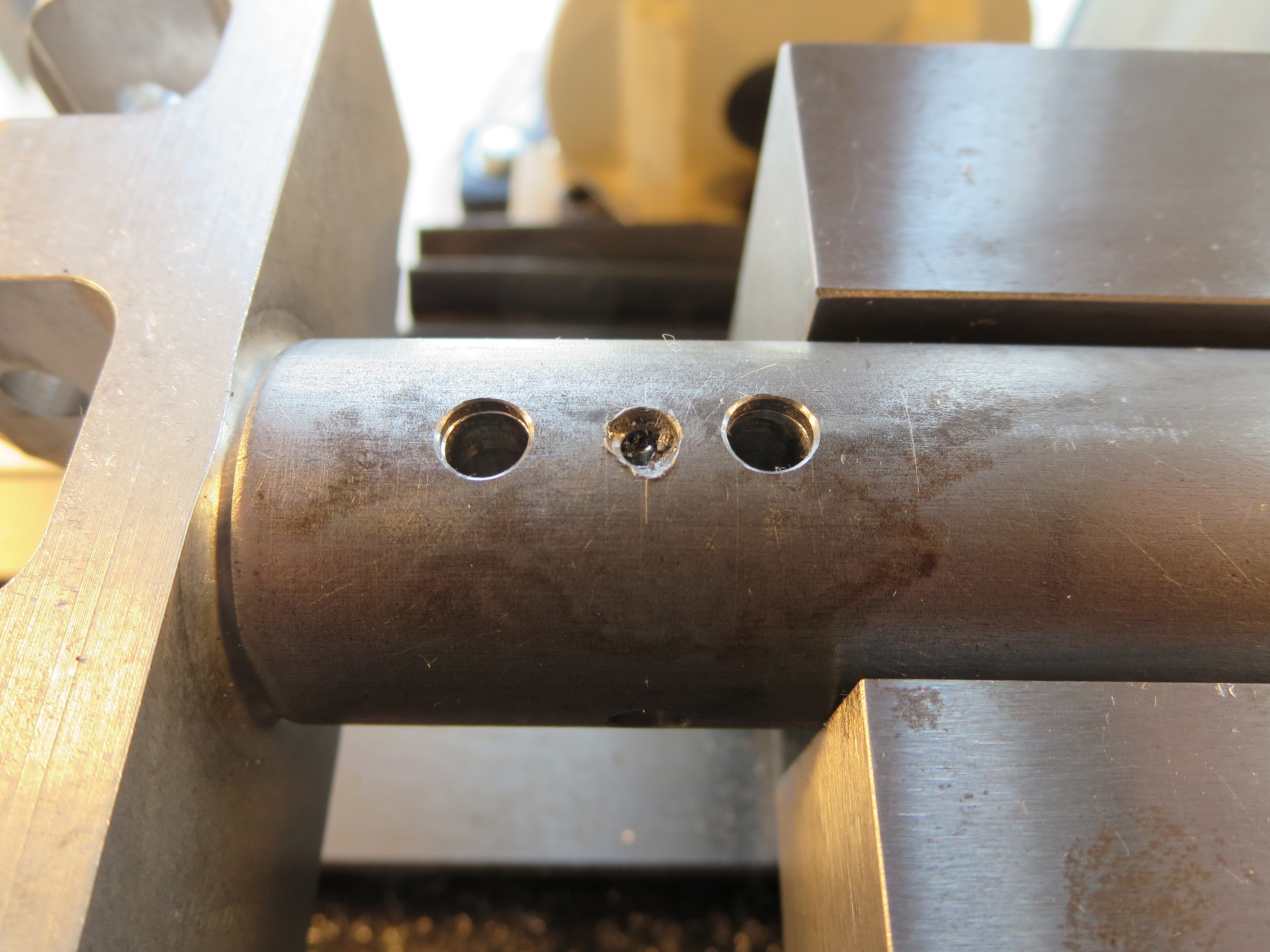
I tried using the "old" rearmost vertical hole first and matching the hole (you can see the hole on the left) Though very, very close, the hole on the other side of the tube was slightly oblong (by about 10 mils). I went ahead and drilled the horizontal cross bolt.
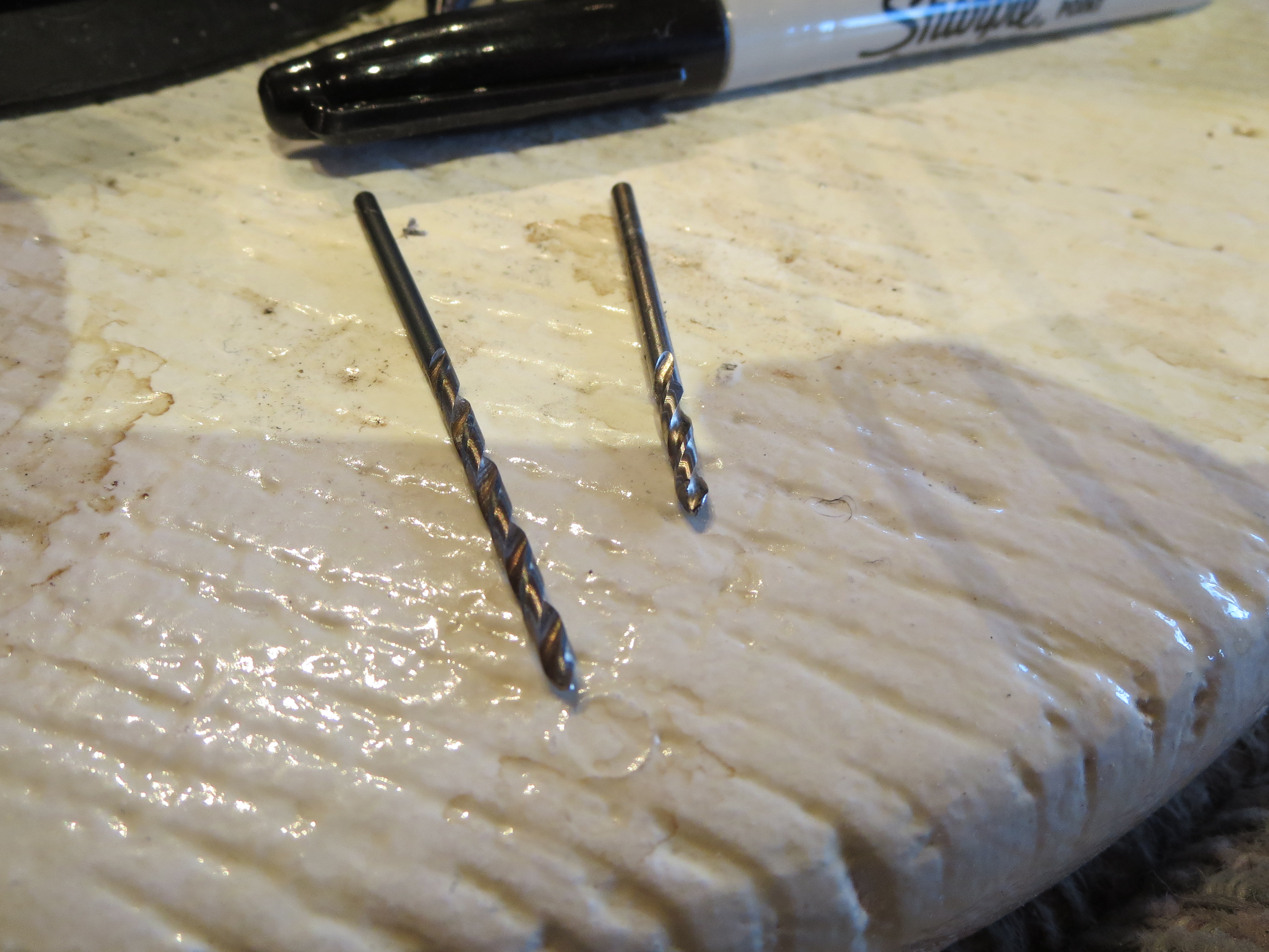
Why the bit snapped I don't know. It was only eating into aluminum at that point. It was well oiled, and I was backing it out regularly to clear chips. I was attempting to use a #30 bit as the pilot and that is probably a little wimpy for a hole this deep. Here you can see the remains of the broken bit with about 0.5" missing (in the mixer block).
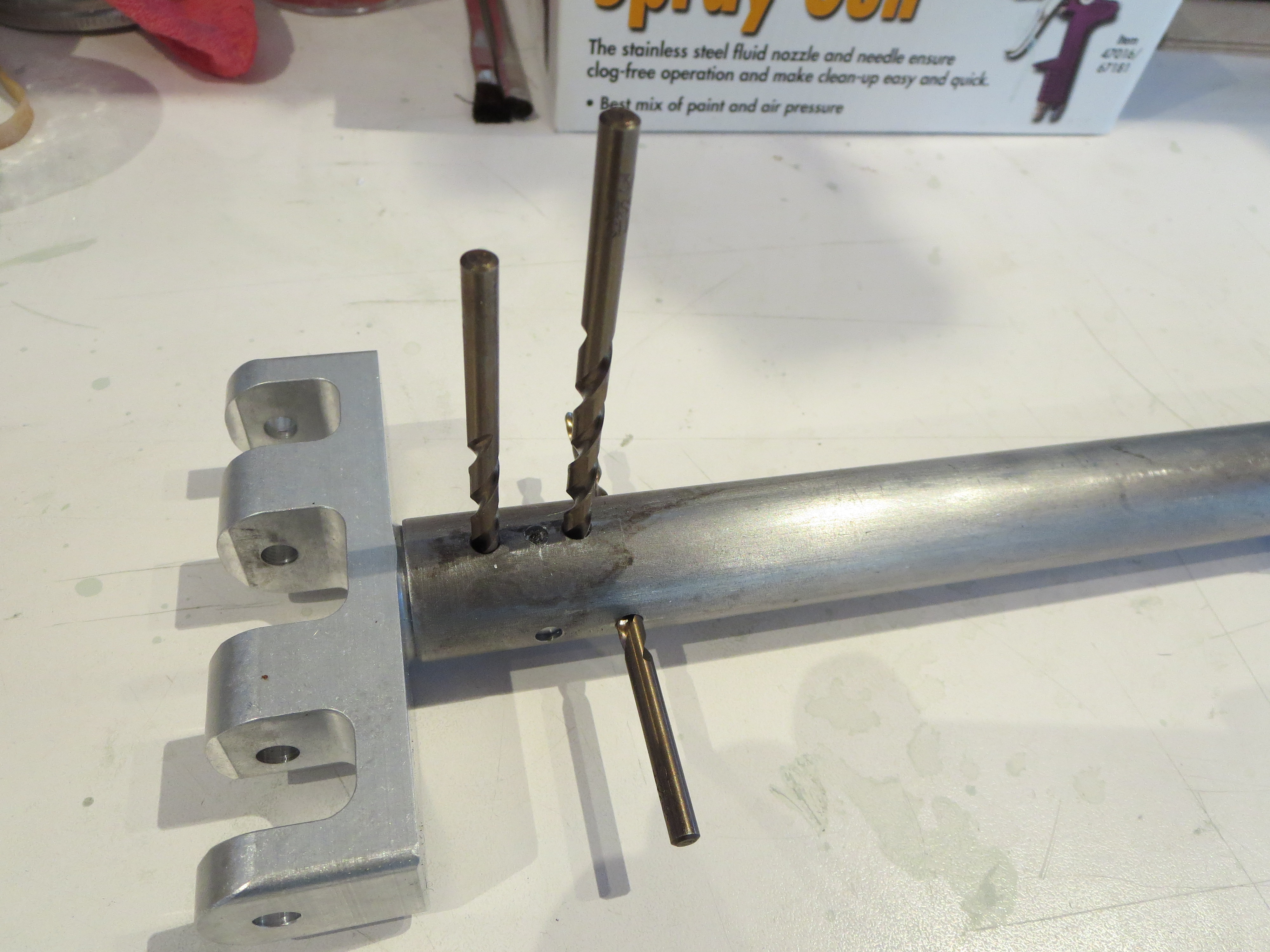
Even though it probably would have been OK, I carefully measured and determined that there was room for a third hole in between the others. You can see the middle drill bit here showing that hole. Pretty busy. The forward most cross hole is perfect, nice and snug. The rearmost one is the one I tried to match - sloppy on the far side. The middle is my auxiliary hole - also nice and snug. OK. Good. Crisis averted.
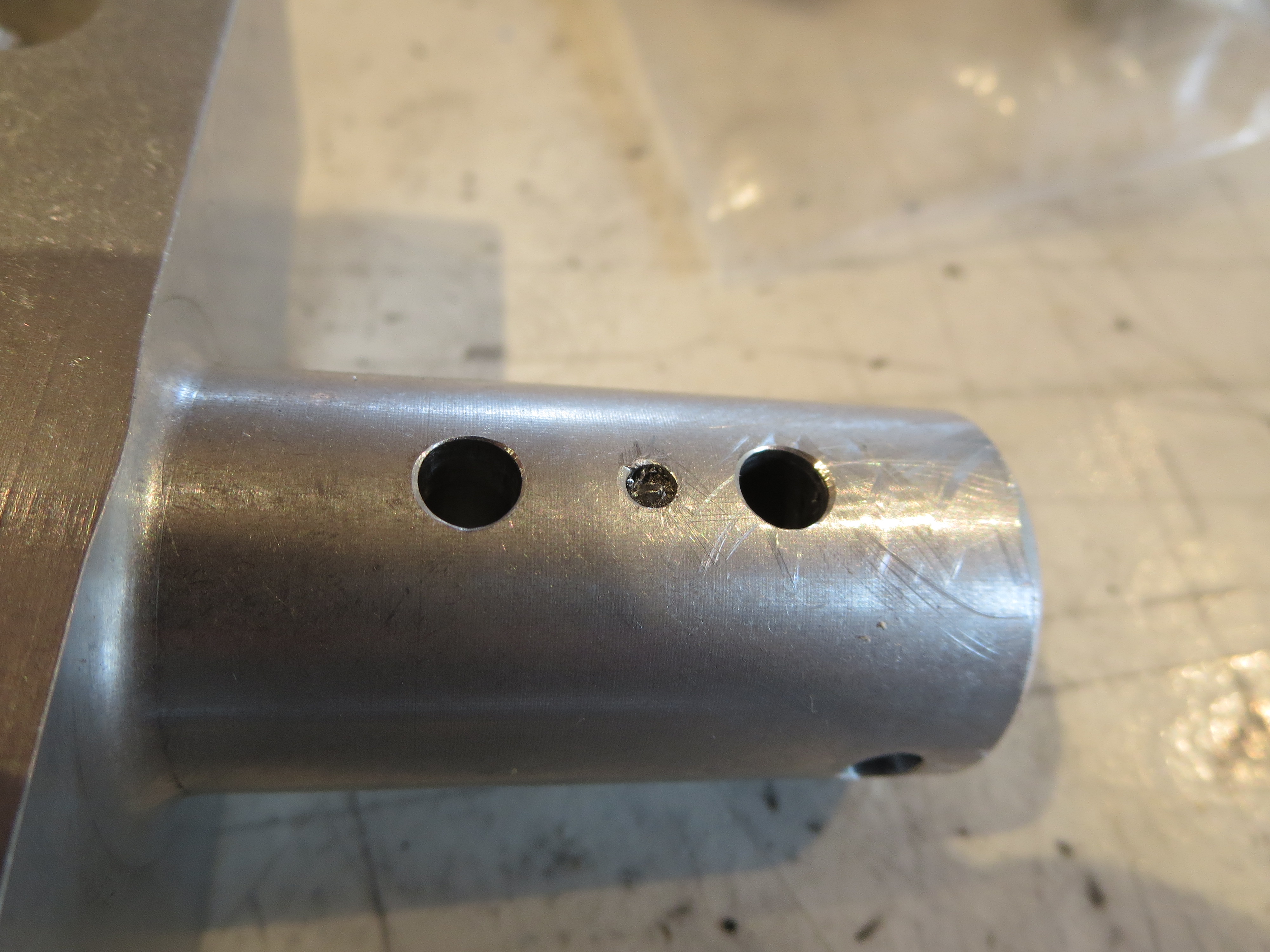
The mixer block removed from the cyclic control tube showing the three holes. Since it is solid aluminum I have no concerns over strength. The broken bit will ride along with me forever stuck in the aborted hole.
The rest of the mixer assembly is a non-event, just assembly with a little sanding to make everything slide together smoothly. Off to paint.
Received New Mixer
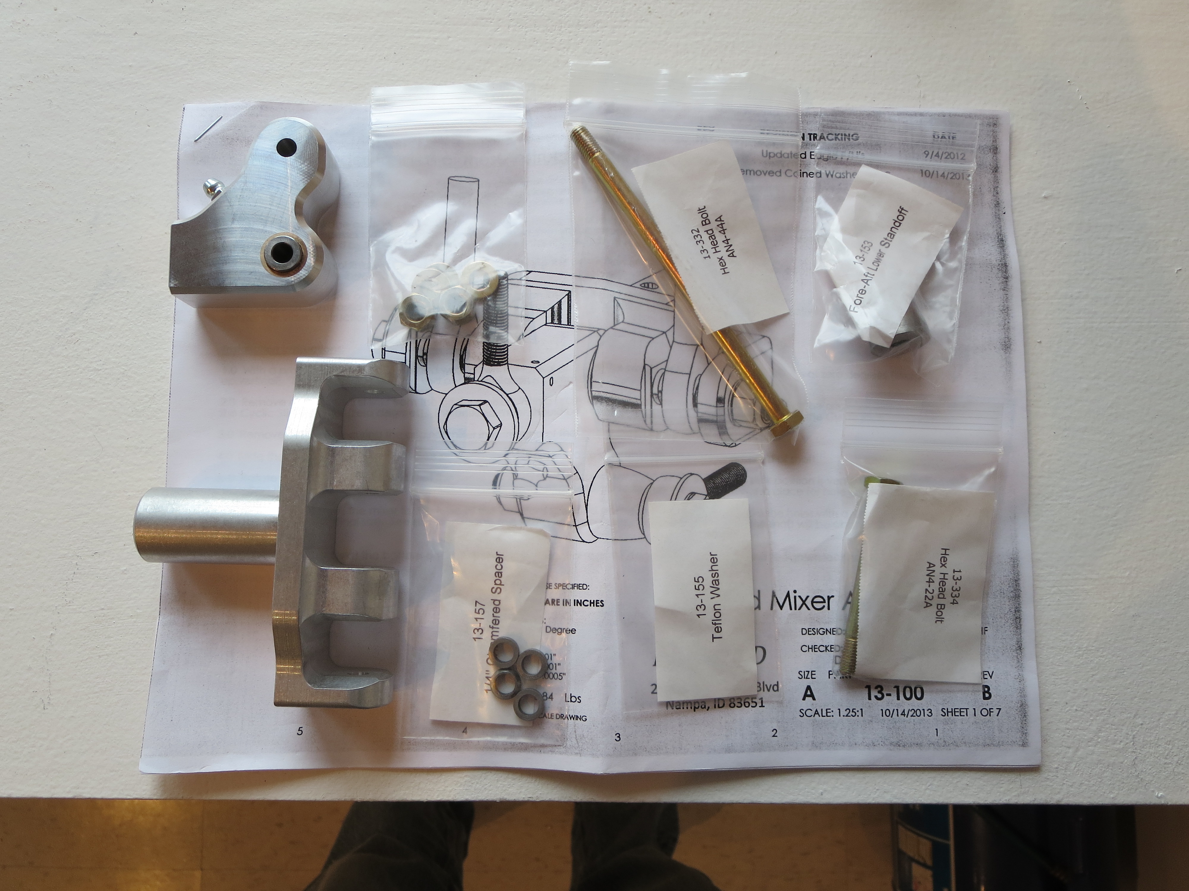
I finally received the new mixer from Blake. Very nice machined parts. What a quantum difference in quality of drawings CAD makes. Can't wait to slide al this together.
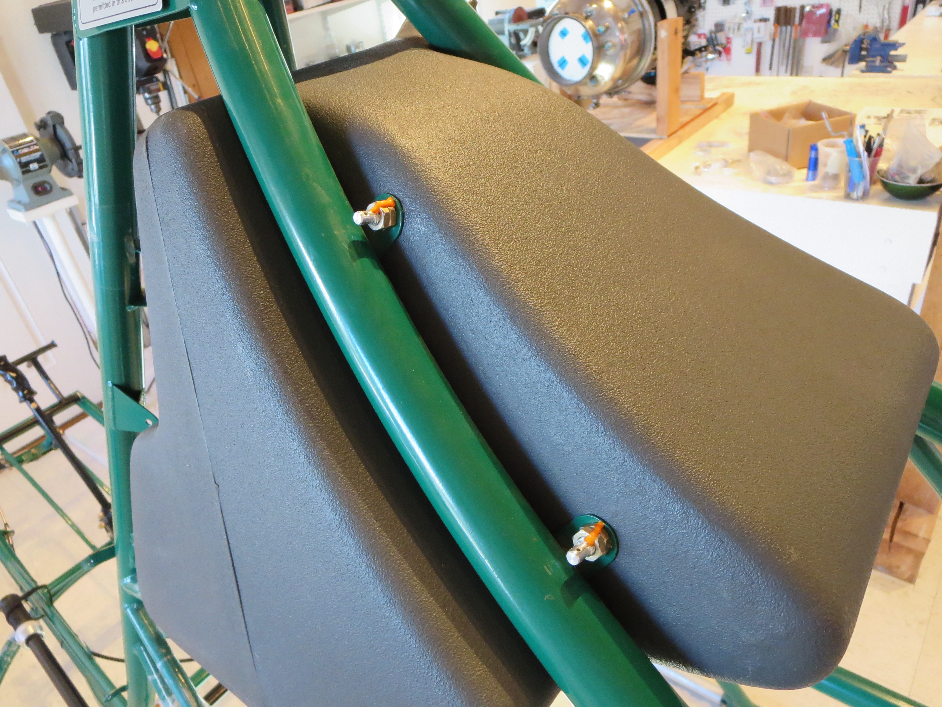
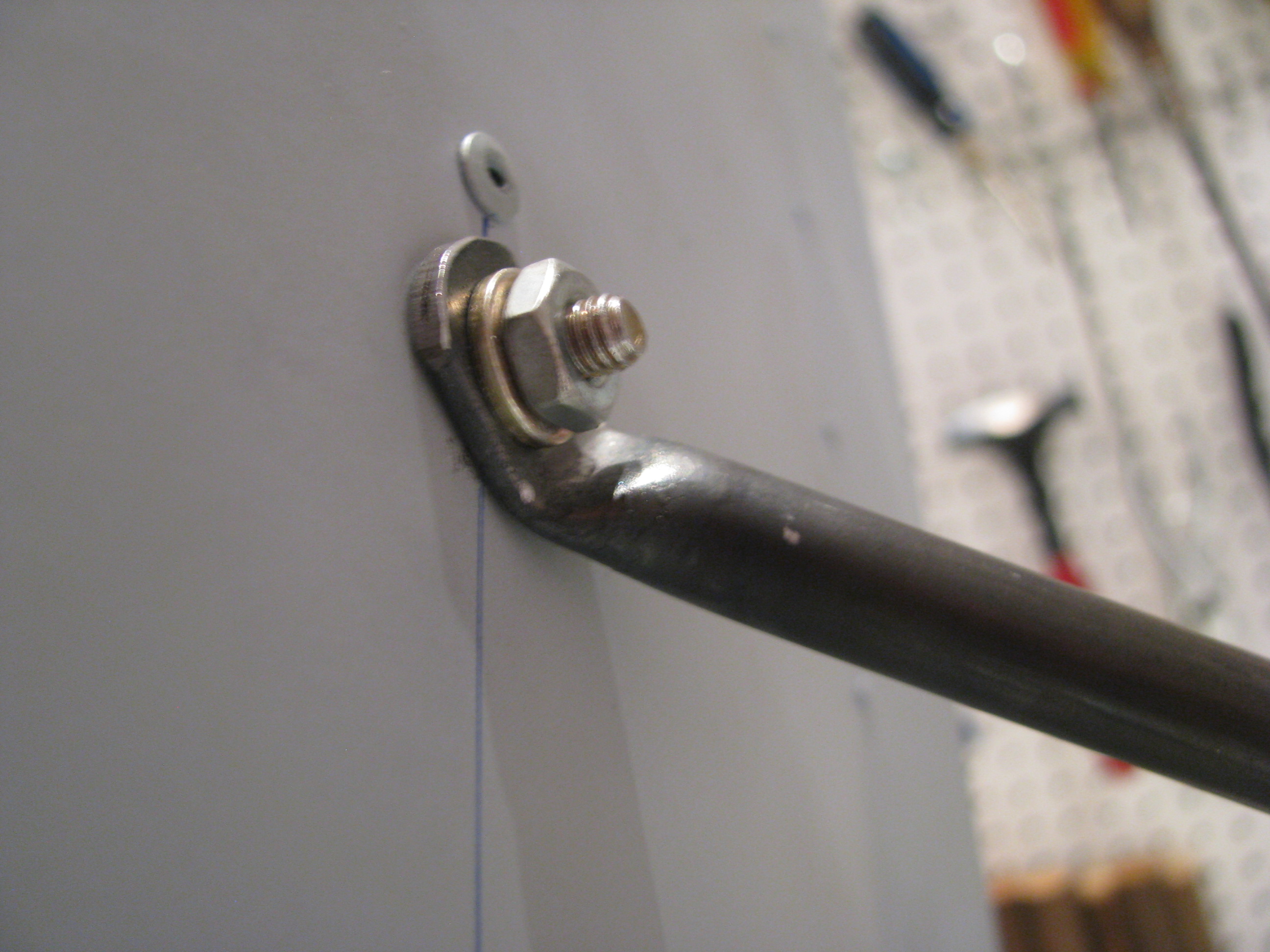
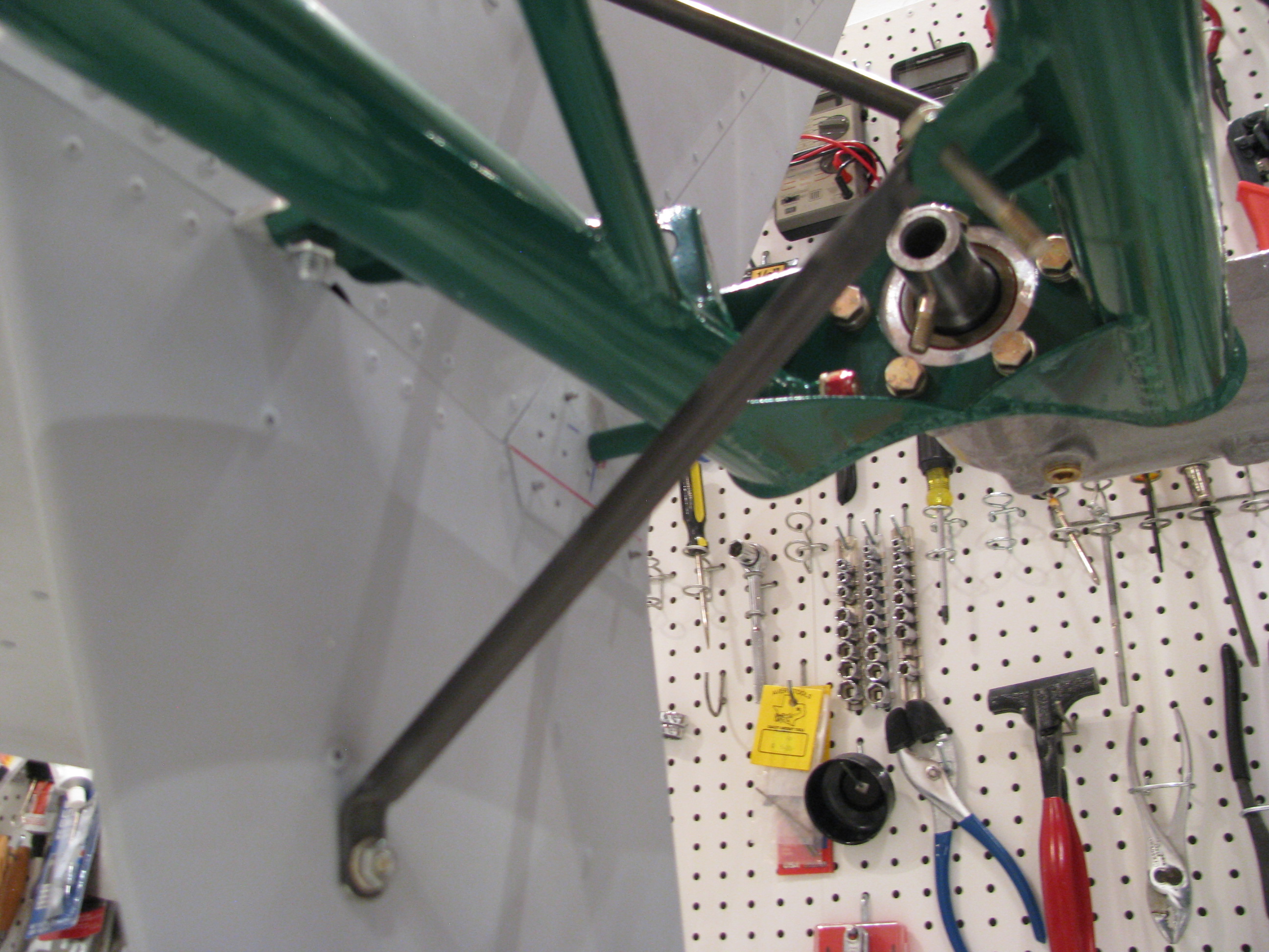
Final Pedal Mounting
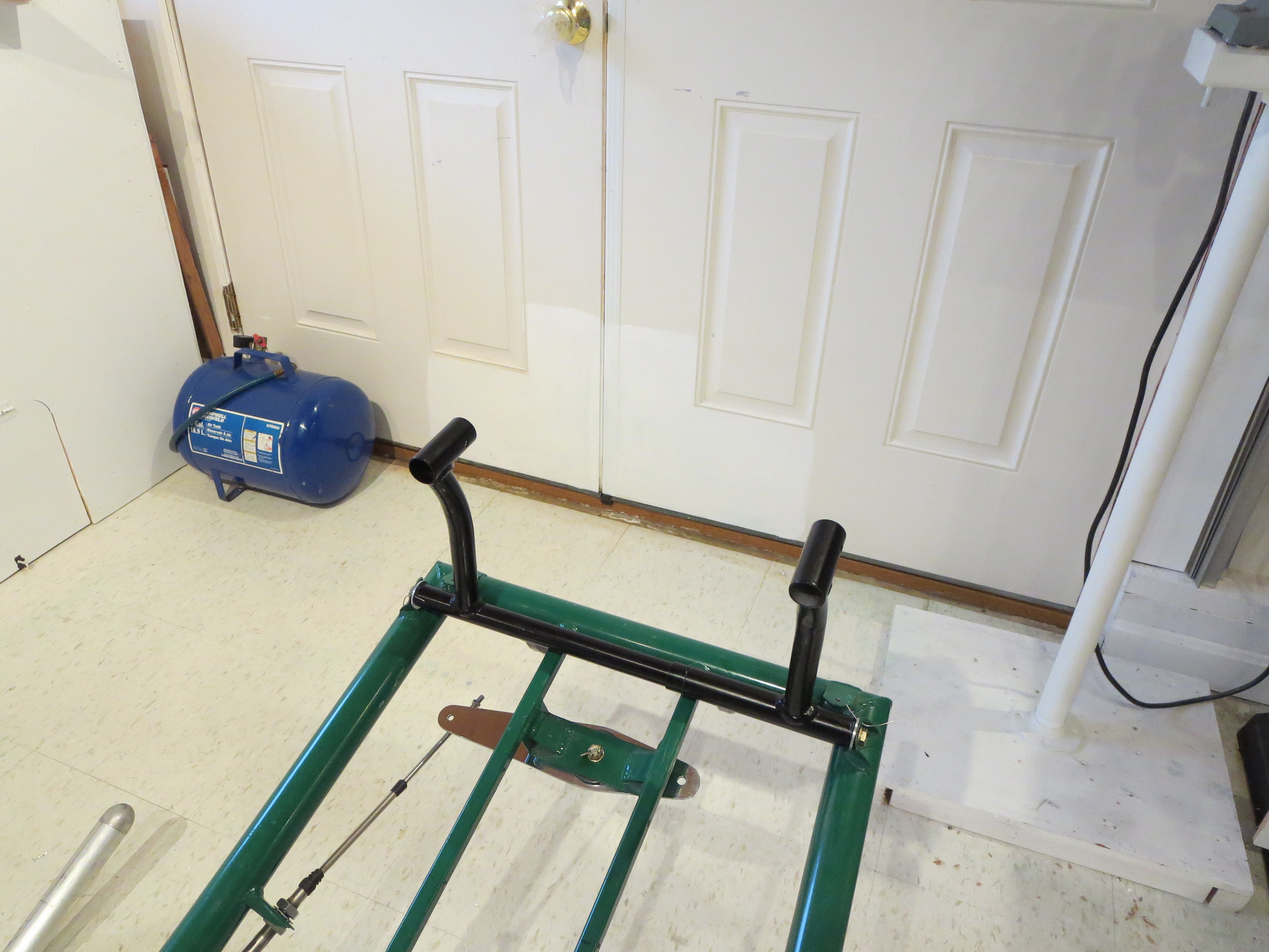
I went to FINAL mount the TR pedals as it is time to start placing some things on the ship for the LAST time now. When I went to snug the bolts up it all bound up and was very stiff. Not good. Controls are supposed to have some damping, but should be butter smooth with no stiction.
After staring at it for a few minutes it became apparent that when the AL bushings are snugged up, they get pulled against the welded steel tabs that mount them to the frame and those tabs are not perfectly square with the mate on the other side of the frame for the opposing bushing. That "tilts" the bushings and cause them to bind in the tube.
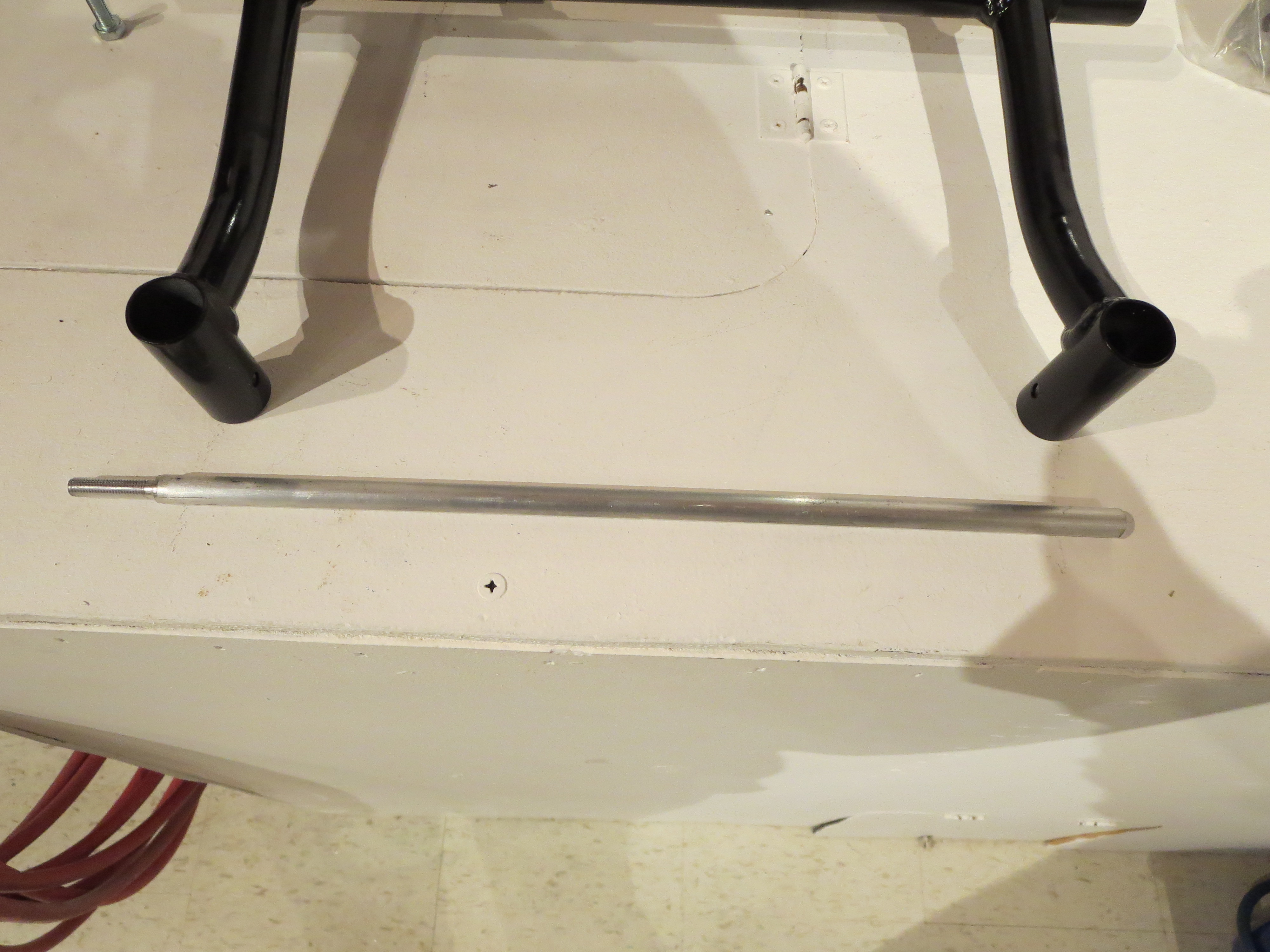
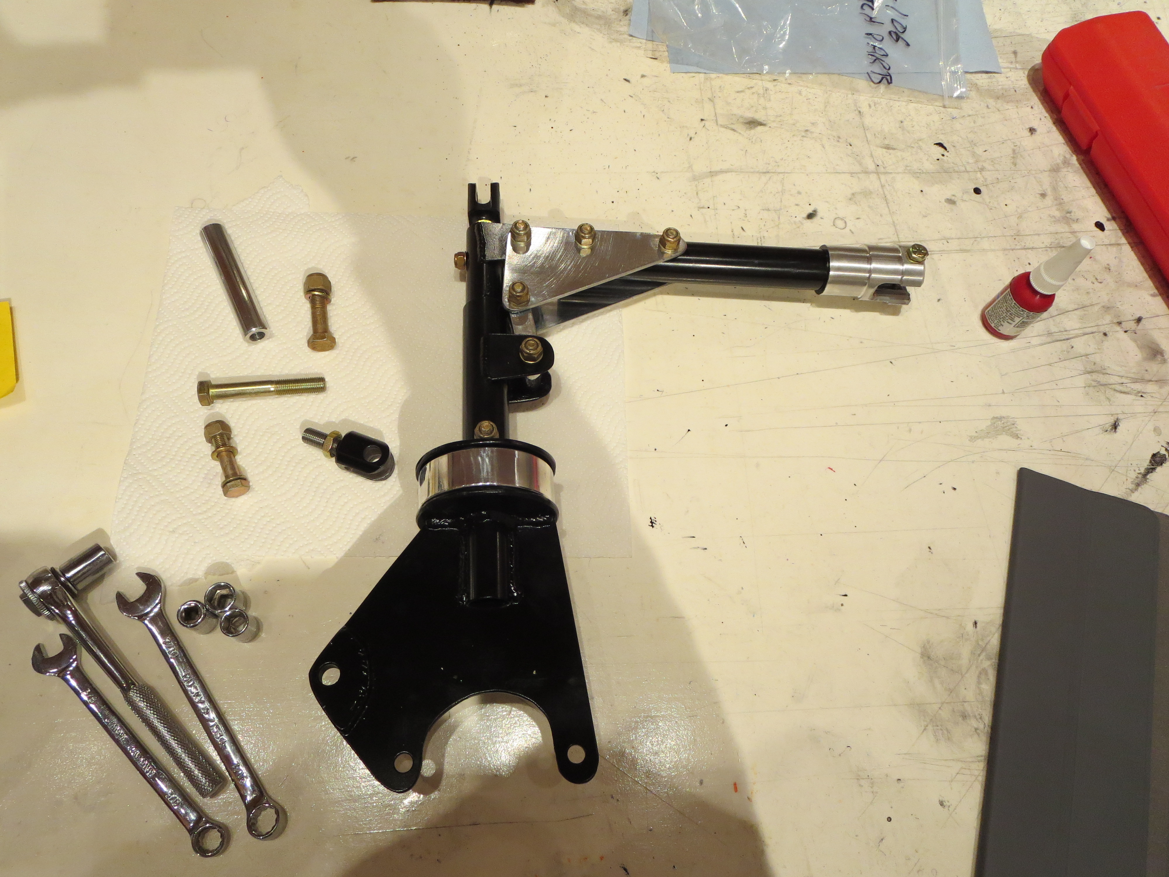
No problem. I have all these machine tools - time to put them to use. I lathed down and threaded an aluminum rod that was the appropriate length to thread into the bushing to "point" to where the alignment was on the opposite side.
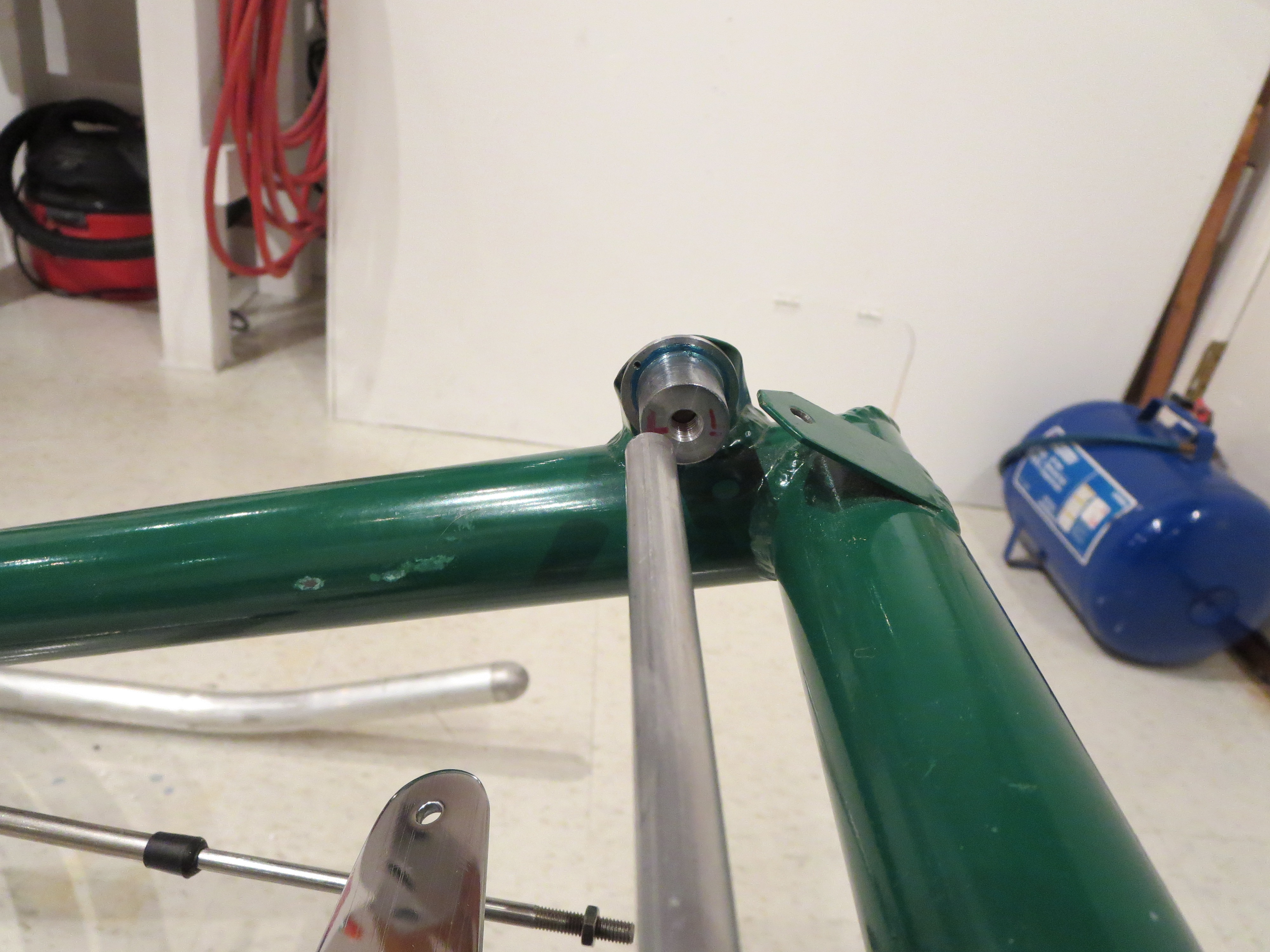
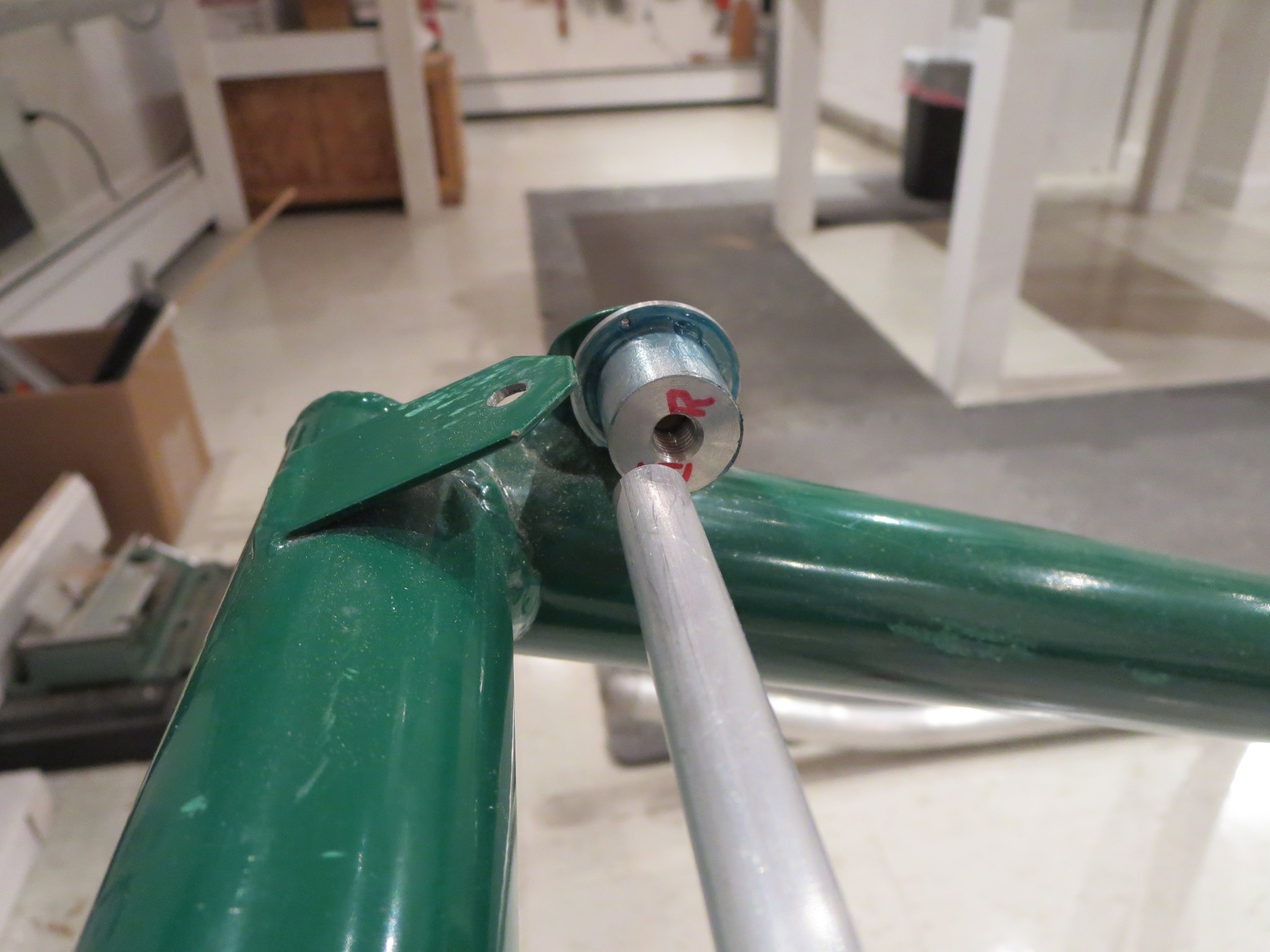
With those very evident visual cues it was very easy to tweak the mounting tabs (it didn't take much) to bring everything into nearly perfect alignment.
Amazing how such a small change resulted in such a large difference in the feel and operation of the pedals. Greased up, snugged up, Safety wired. The first permanent moving part. Lots to follow in a short period. Nice.
Lower Panel Crafted
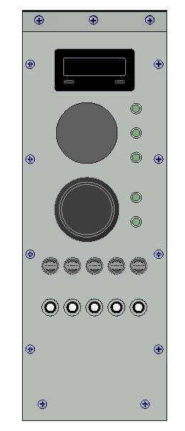
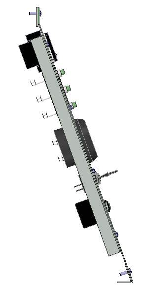
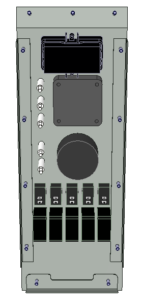
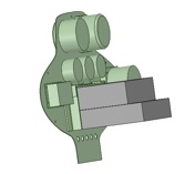
Start with a quick CAD model of the instruments and panel. If anyone is interested in the solid models I used, just email me and I will post them.
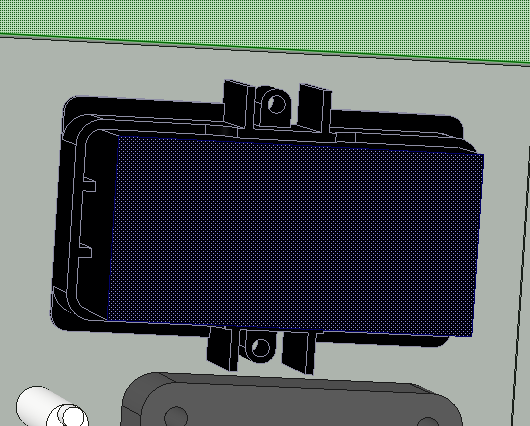
I almost neglected to model the rear retaining ring around the Red Lion tach. Can;t skip that because it's quite a large thing. Once everything is modeled, it is easy tp check for interferences and tweak the position if required.
Once the modeling is complete, add some dimensions and make a detailed drawing as I did HERE. This is the primary reference sheet when machining the holes in the sheet.
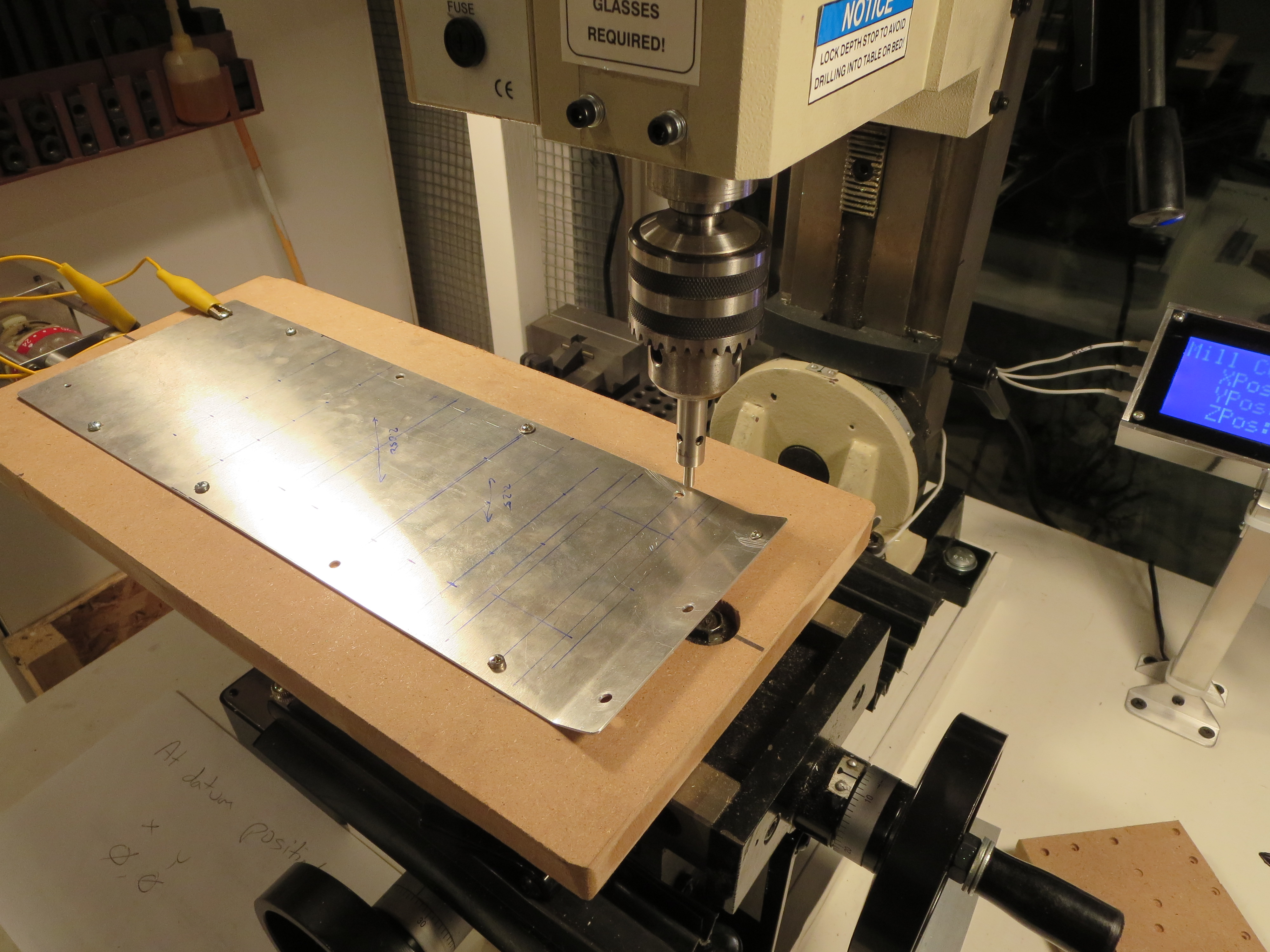
The blank queued up on the mill. Prior to this the blank had been cut and then fit into the instrument pod lower. The side mounting screws were drilled in assembly with the support strips in the pod. Perfect alignment prior to this drilling/milling operation.
On the mill I bolted a piece of MDF to the table (mounting bolt recessed, of course). Then the blank was trammed to the mill so the edge was in perfect parallel alignment with the quill. Very small wood screws are then screwed through the mounting holes to solidly affix is to the plate. The front mount hole and edge are the home reference.
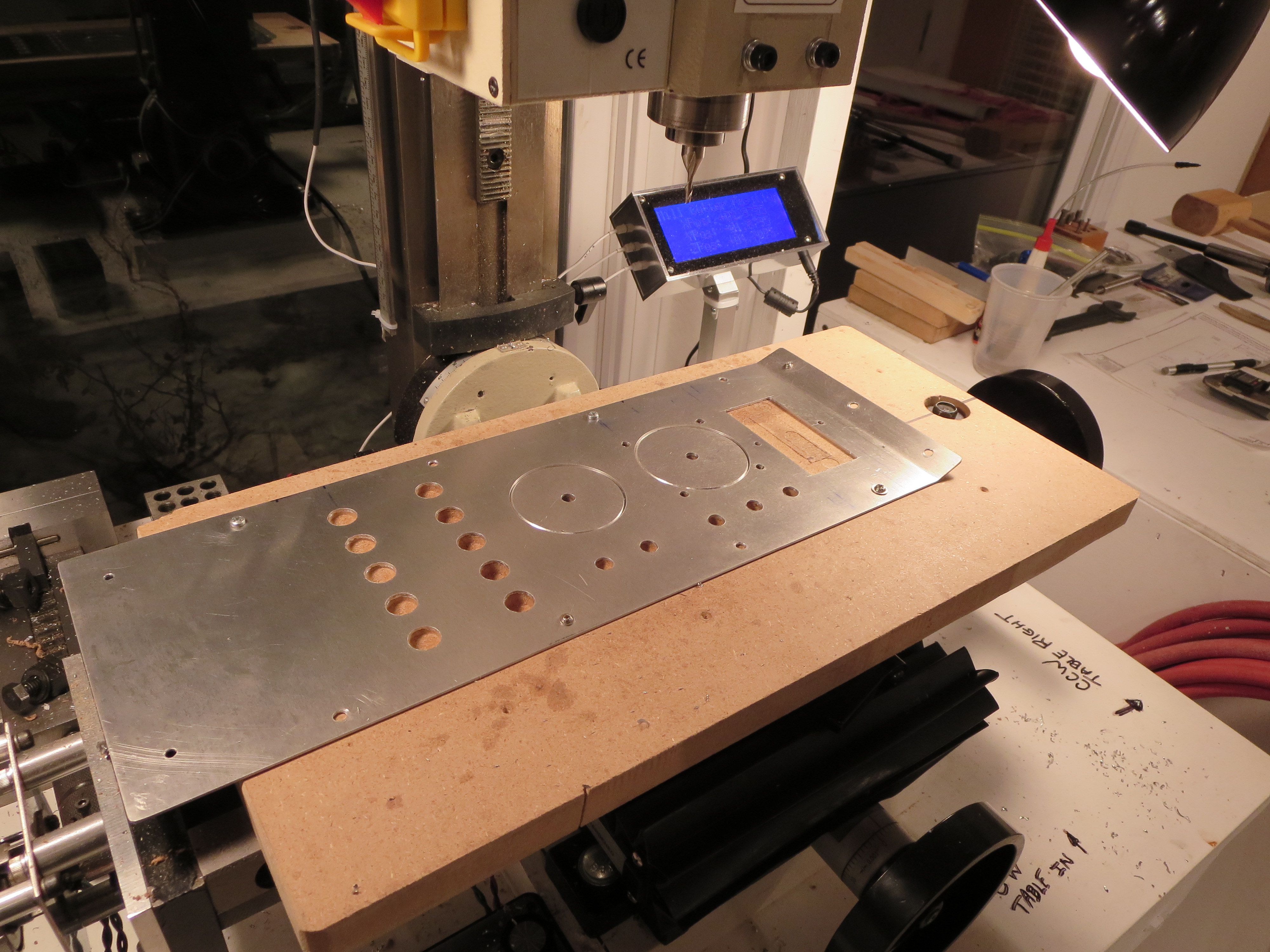
The Lower Panel machined. I love that little mill. Though time consuming, the accuracy is impressive. Digital readouts on each axis make repeatability and accurate positioning very easy. I used my hole jig for the circles, and milled out the tach square with a 3/8" end mill. The corners were finished with an 1.8" end mill. If needed I will file them down.
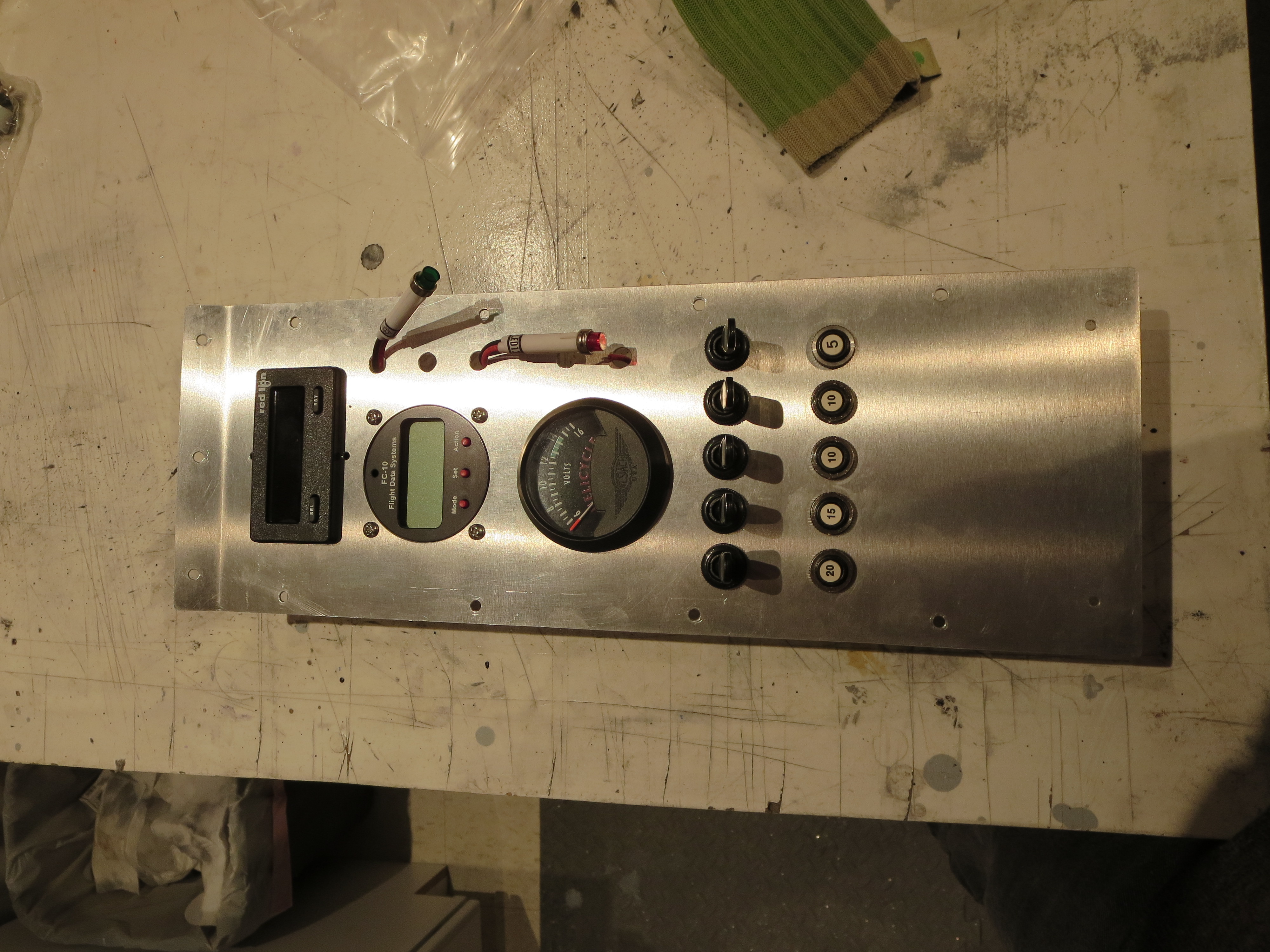
All the stuff preliminarily fitted. My holes for the indicator lights were a bit small and the fuel monitor hole needs some trimming, but by and large the fit is pretty good. All the holes are alignment nicely and very square.
DVD Index
I finally got around to indexing the contents of the DVDs. At this point I need to find certain things quickly. All the DVDs have been loaded onto my iPad so I can reference them quickly in the shop. Also shown is the order in which the items should be completed for final assembly.
| DVD Contents | ||||
| DVD | Group | Sequence | Subject | SDM Order |
| 1 | 1,2 | 1 | Full and Half Door Construction | |
| 1 | 1,2 | 2 | General Construction and Fitting Landing Gear | 1 |
| 1 | 1,2 | 3 | Cabin and Trim Fins- Floor Pan, Pod, Cabin, Windscreen, chin window | 2 |
| 1 | 1,2 | 4 | Cabin and Trim Fins continued - Trim fins and mounting. | 3 |
| 2 | 3 | 1 | Fuel System | 4 |
| 2 | 3 | 2 | Direction Controls, Cyclic Controls | 5 |
| 2 | 3 | 3 | Fitting of Controls to Ship | 6 |
| 3 | 4,5 | 1 | Main Transmission Fitting and Lift Strut | 7 |
| 3 | 4,5 | 2 | Tail Rotor shaft construction. TR gearbox. Tailrotor fitting. | 10 |
| 3 | 4,5 | 3 | Tailrotor balance and general information about design | 8 |
| 3 | 4,5 | 4 | Tailrotor gearbox mountings and alignment | 9 |
| 3 | 4,5 | 5 | Control rod fitting and swashplate alignment. | 15 |
| 4 | 9 | 1 | Turbine engine installation and control information | 12 |
| 4 | 9 | 2 | Governor construction and installation notes. | 13 |
| 4 | 9 | 3 | Turbine plumbing and fittings. Clutch Assembly. | 11 |
| 4 | 9 | 4 | Motor mount fitting and alignment | 14 |
| 5 | 6,7 | 1 | Rotor head fitting. | 16 |
| 5 | 6,7 | 2 | Rotor Blade Doubler Bonding | 17 |
| 5 | 6,7 | 3 | Rotor doubler continued and end caps. | 18 |
| 5 | ,67 | 4 | Rotor mounting and balancing. | 19 |
| 6 | 8 | 1 | Battery Box Mounting and general wiring information | 20 |
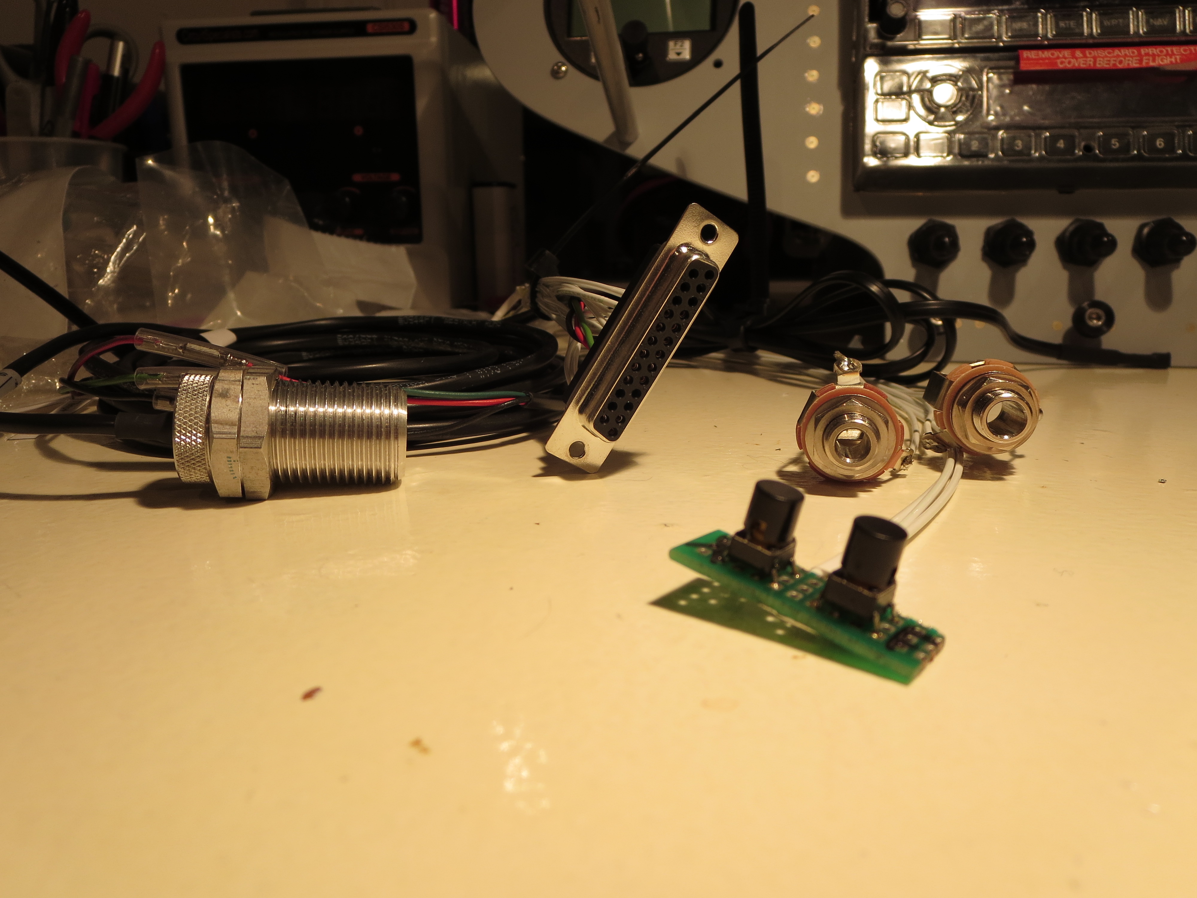
Finished Packaging Compass
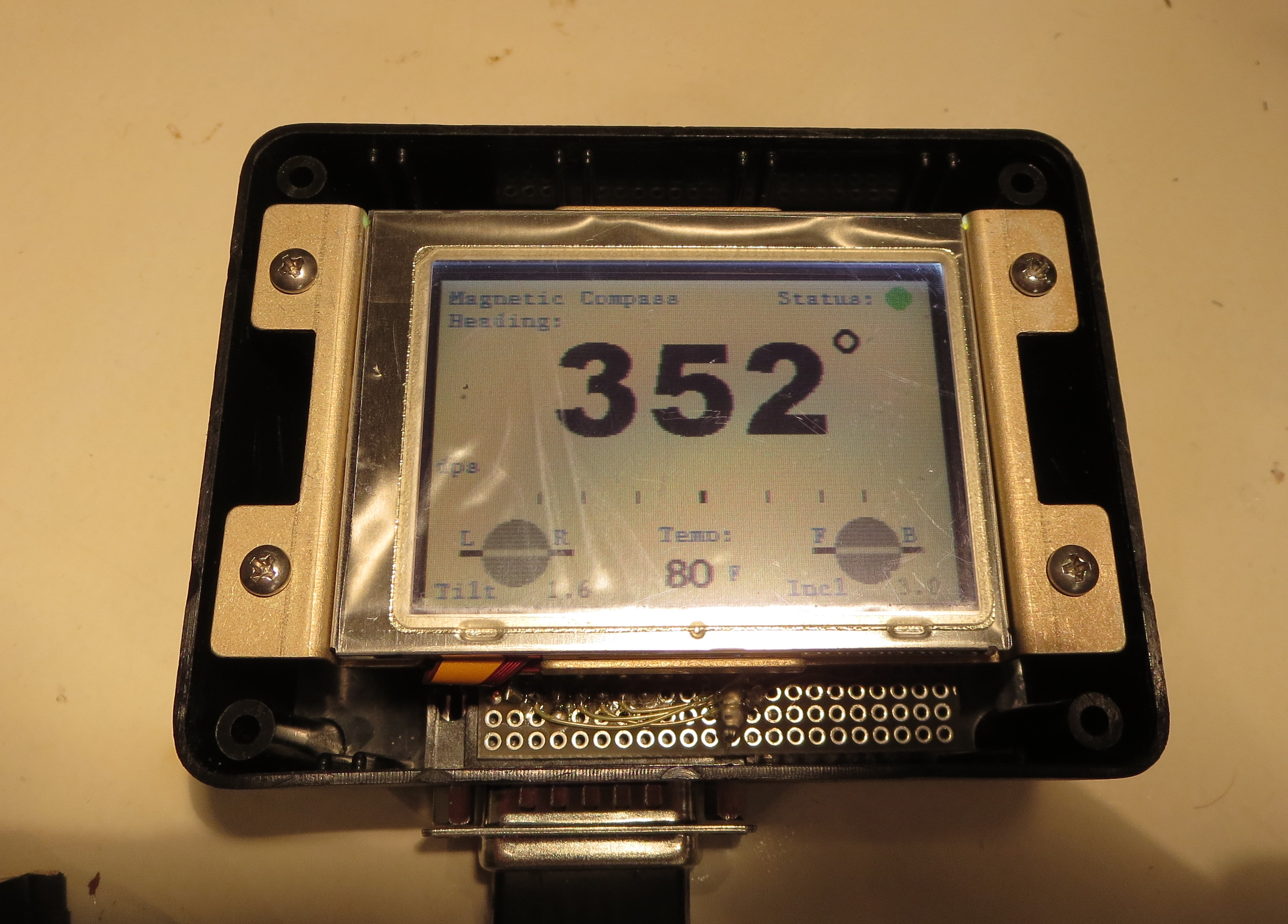
I finally finished packaging my homemade electronic compass. Small project box with some machined risers to house the thing.
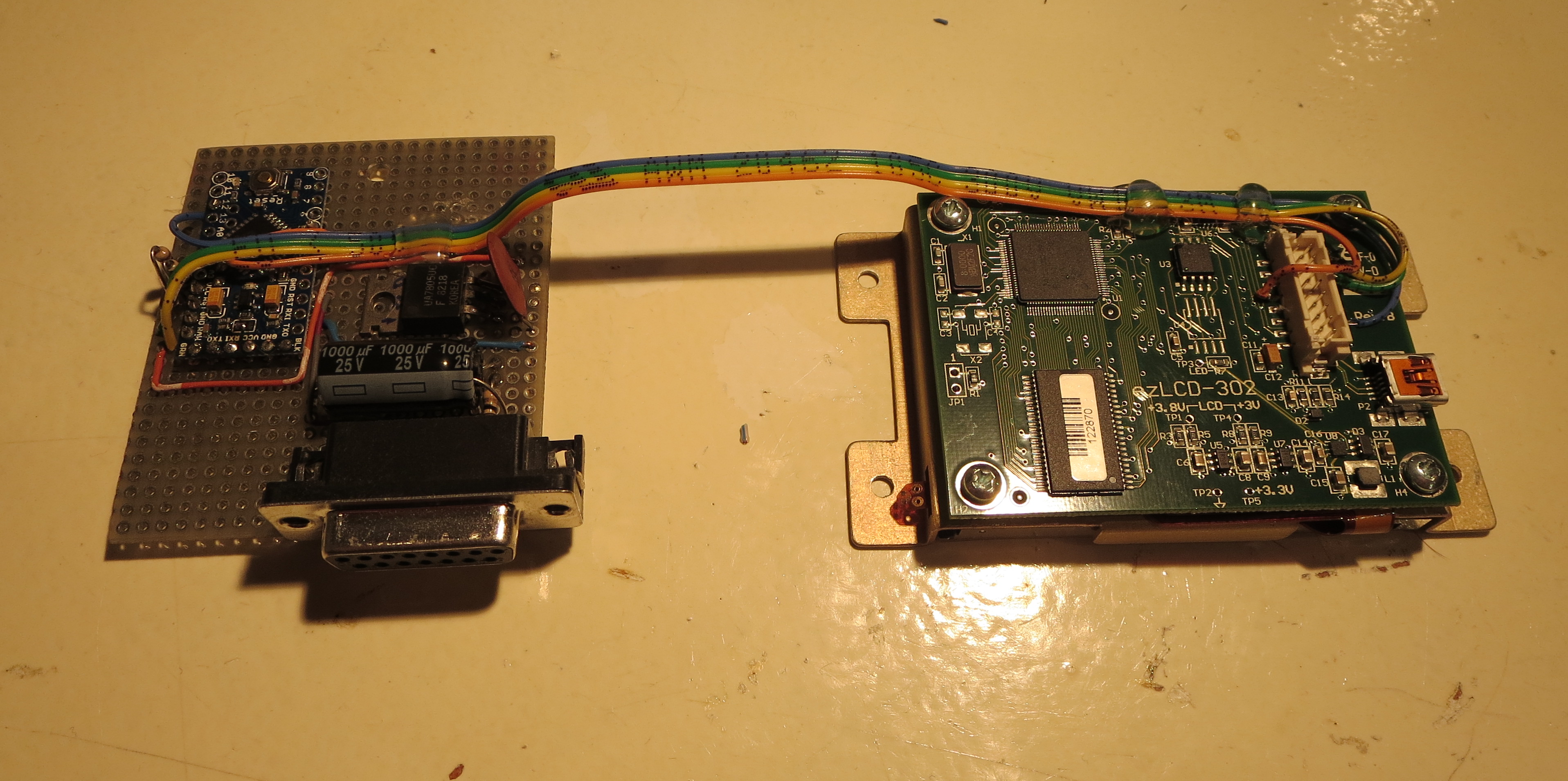
That's just an experimenter board with the Arduino mounted and a 7805 linear power supply. Power draw is 0.18A at 12V, so about 2.2W. More than I expected, but not too bad overall.
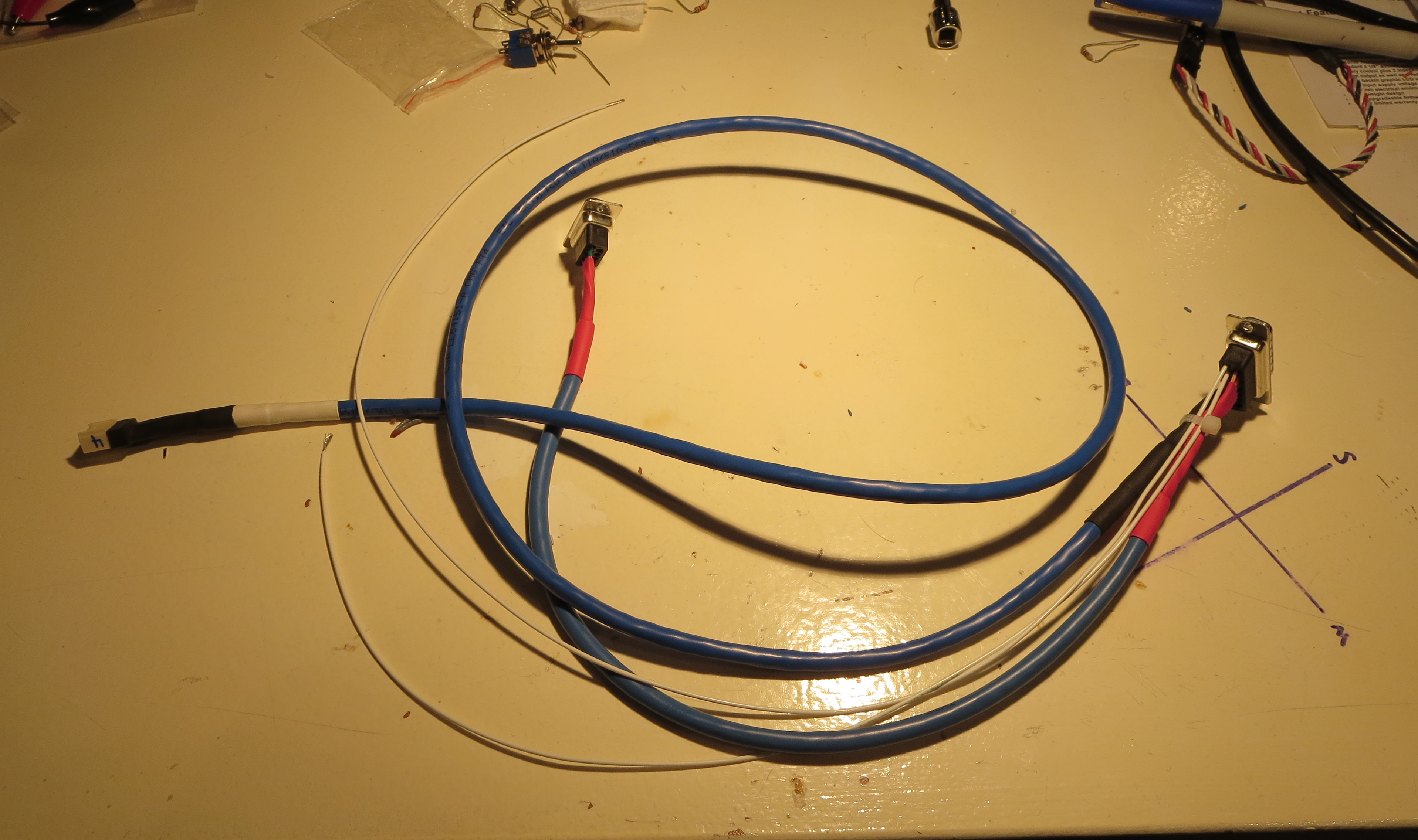
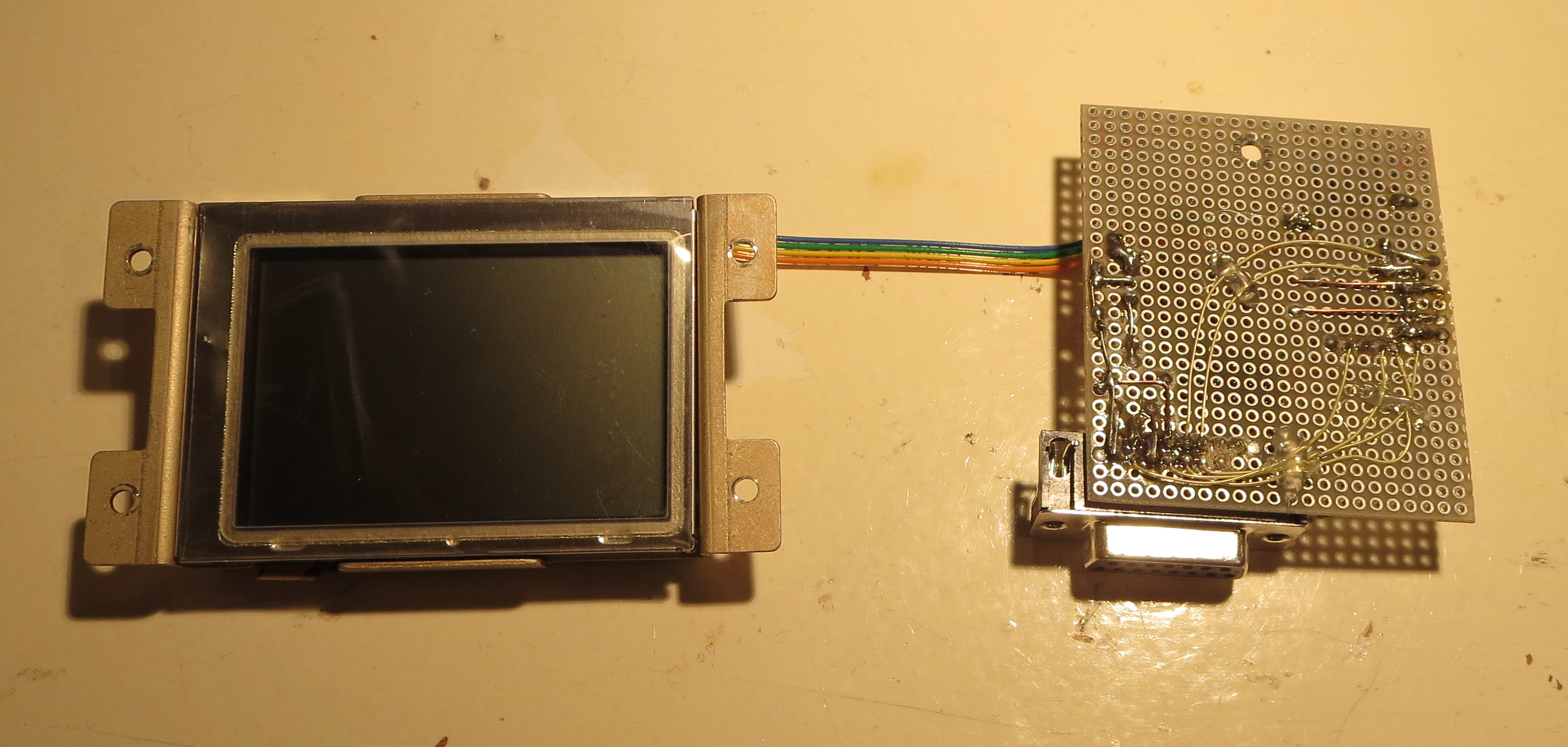
Custom wiring harness connects to unit, power, sensor, and a DSUB9 in case I want to update the firmware with calibration data once its in the bird.
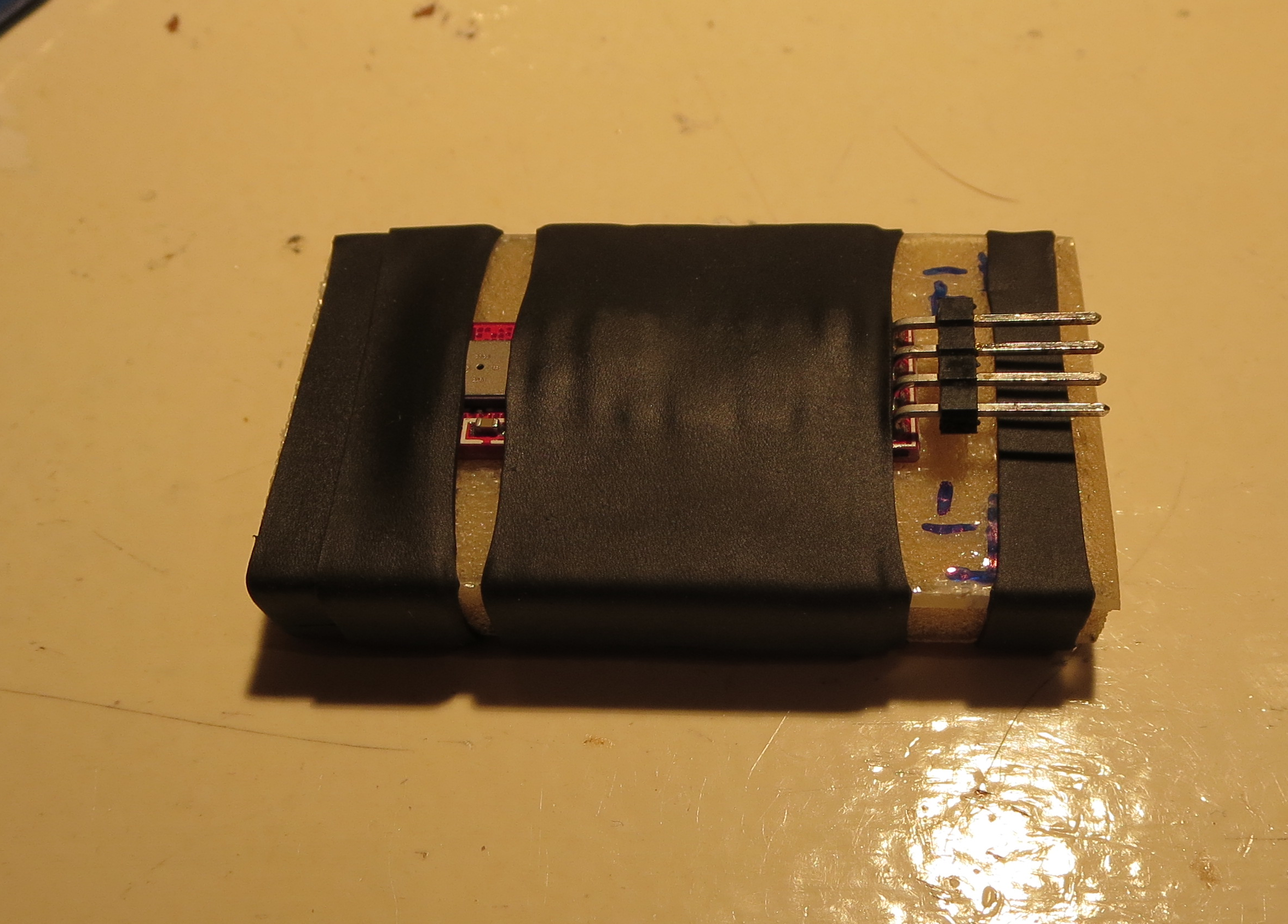
Sensor is shrink tubed to a little chunk of fiberglass. I will probably just tie wrap this to a fiberglass platform at the from of the pod's interior.
Wiring notes are here. I uses NotesPlus HD on the iPad to take hand notes in the shop. Better than paper and you get an instant electronic copy.
N-Number Reserved
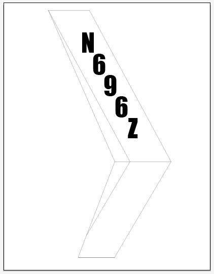
Hooray! I got notice of my reserved N-Numbers from the FAA today. Though not difficult to get or an especially tricky milestone, it IS an indication of the project progressing.
I ordered some custom vinyl lettering from DIYLettering.com; Pre-cut green vinyl letters 3.5" tall. The font is "Impact", which looks very readable.
Panel Wiring
Instrument Cluster wiring harness is fabricated and installed. This is not especially hard, just tedious. I did not do a formal schematic since there is no real circuit design here, just connecting point A to point B. It was all tracked with spreadsheets. Once routed and the ends crimped, the bundles were lashed with spiral wrap nylon to tidy everything up. I drilled holes on the back of the GPS/COMM tray so everything could be hard-secured down. No wiggling wires. It is all very solid.
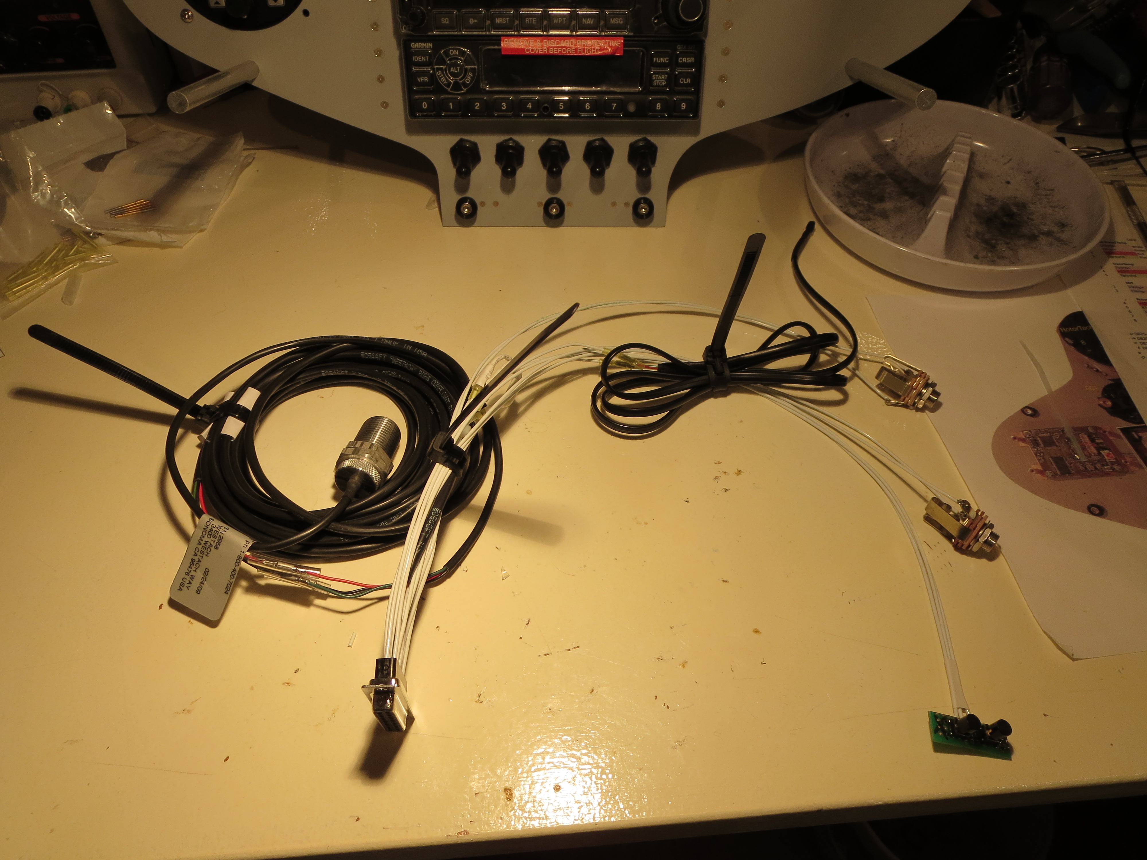
Of course once the wiring was done I had to make up a little test harness with power and switches for the XMIT and COMM flipflop as well as power and the sensors that NEED to be attached when powered up (the tach sensor).
Ahhh the money shot! Everything powered up and is functioning OK as far as I can tell. I rigged up antennas and could send and receive over the radio to my handheld and get GPS position data accurately.
One thing that became immediately apparent is that the COMM draws HUGE current (comparatively) when transmitting versus receiving. Nominally the panel was drawing just under 2 amps, but it spiked to about 4 amps, and quickly dropped to 3 amps when transmitting. Wow.
Hap Miller Bits
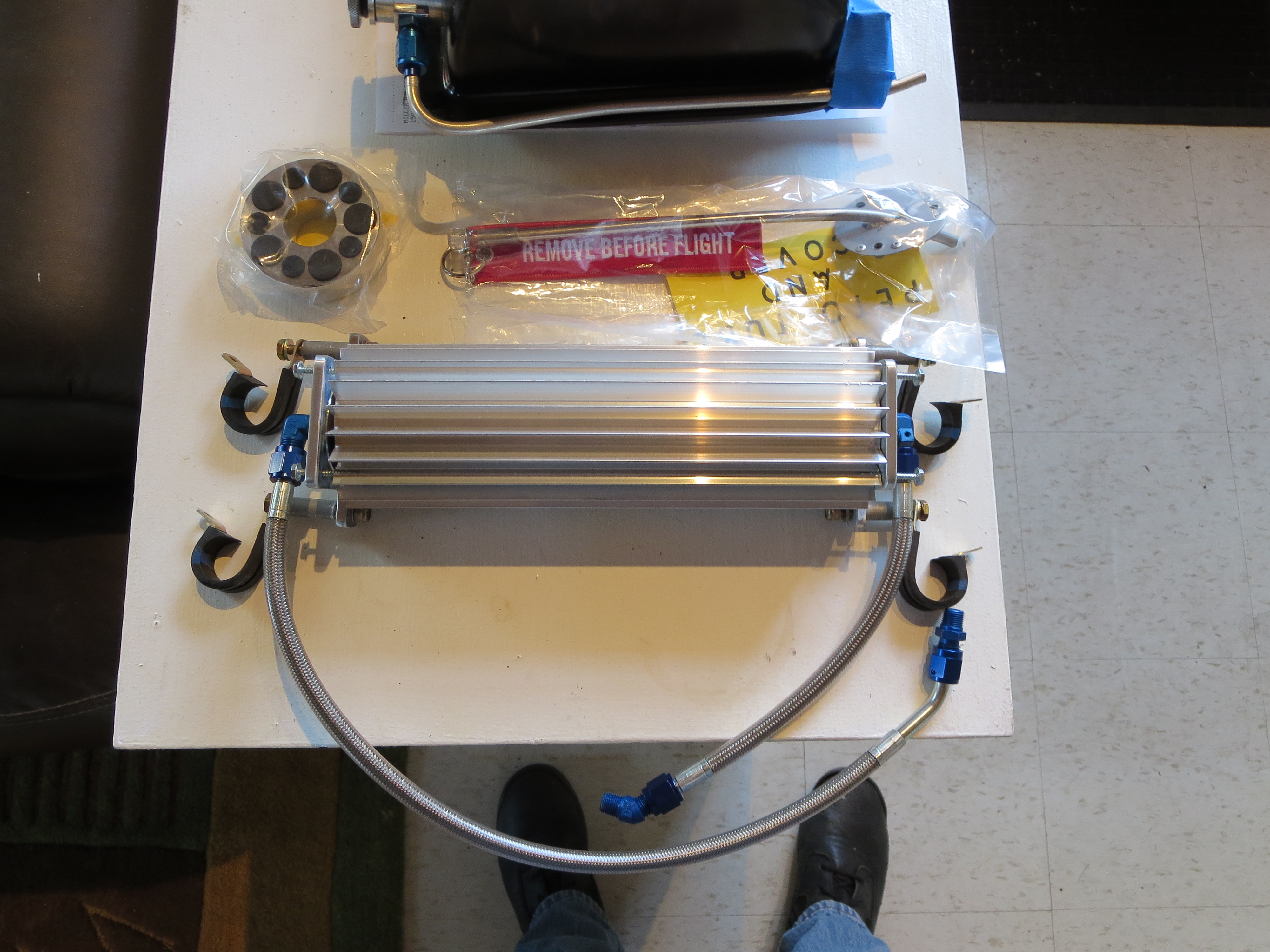
I ordered a bunch of bits and pieces from Hap Miller. Earlier I ordered and received his machined lift strut and it was of very good quality, so I wanted to see what else he has. Turs out a lot.
Here is the transmission oil cooler, clutch disk, and welded pitot tube. Nice!
Hap claims that the "T" on the oil return to the tank actually impeded the return oil flow, so he recommends second fitting to return the oil independently and will add one to your tank. He also has a nice machined cap with integral dipstick.
Lastly are the battery boxes. These mount just behind the transmission and accommodate a pair of Odyssey PC680 batteries. Nice aluminum welding work. It will be a shame to paint them and cover up those nice beads.
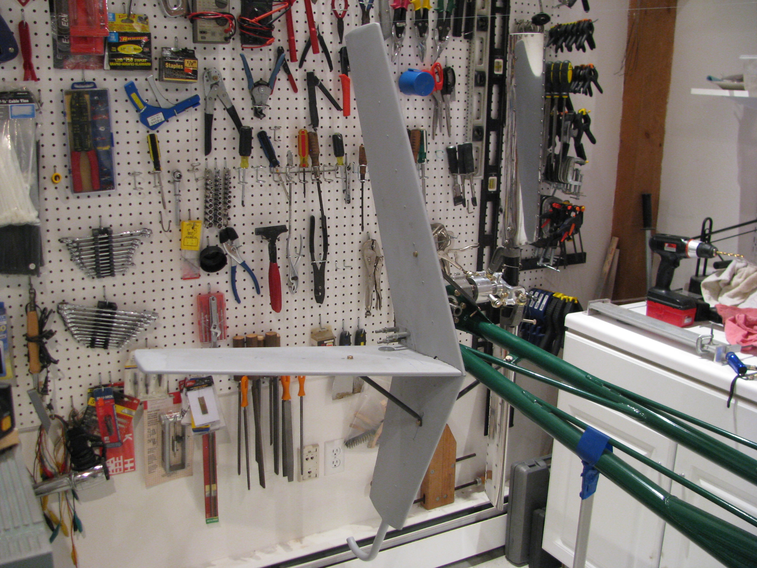
Fin Painting
The first “real” parts painted were the fins. This is Eastwood single-stage urethane. I first practiced on a couple sheets of aluminum I had in the shop, and good thing. There was a fair amount of fiddling with the gun and the first one was a mess.
Keeping the piece flat and getting the second and third coat relatively heavily allowed for a nice flow out. Very smooth. A little orange peel. Not much.
My one flaw is on the underside of the horizontal fin. The Fin slipped down the jig on which I had it and stuck to the piece of MDF I had underneath it. I will have to scuff this and repaint this side.
This is the vertical fin. Overall I am happy with the result. The only issue is that the Eastwood “Bright White” is not nearly as “bright” as I would have thought. It is slightly more grey than absolute white. I am getting used to it, though.
Now that the fin is painted I can select an N-Number and affix it to the fin. Progress.
Ground Plane Paint
For the structural parts I bought some enamel paint that matched the frame powder coating. This is the ground plane for the comm antenna.
Pre-Wiring
Starting in on the wiring of the panel. Have practiced crimping and roughly mapped out the wiring pathways. Power on one side of the avionics stack and a large 37 pin DSUB for all the signals that leave the panel on the other side.
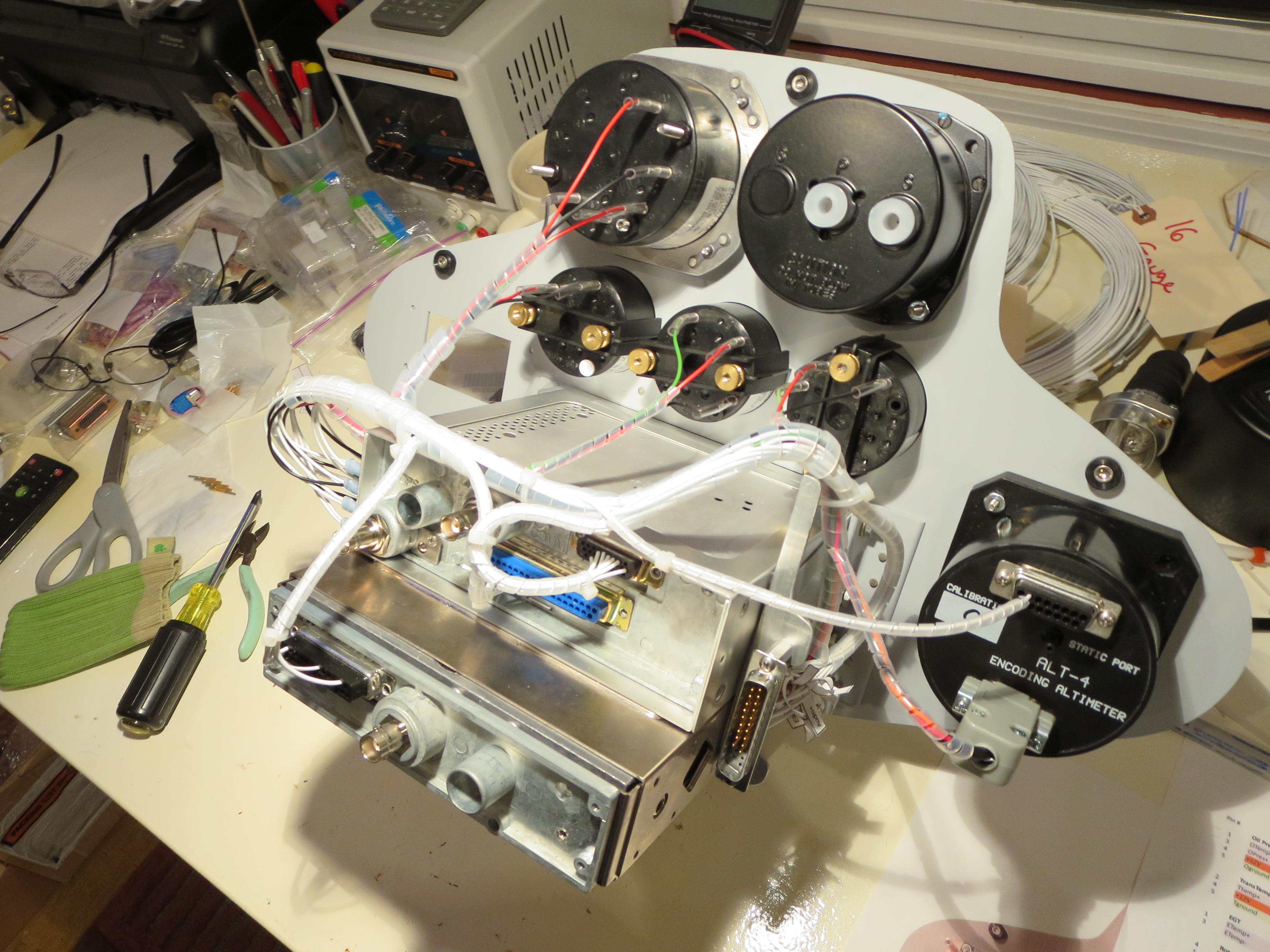
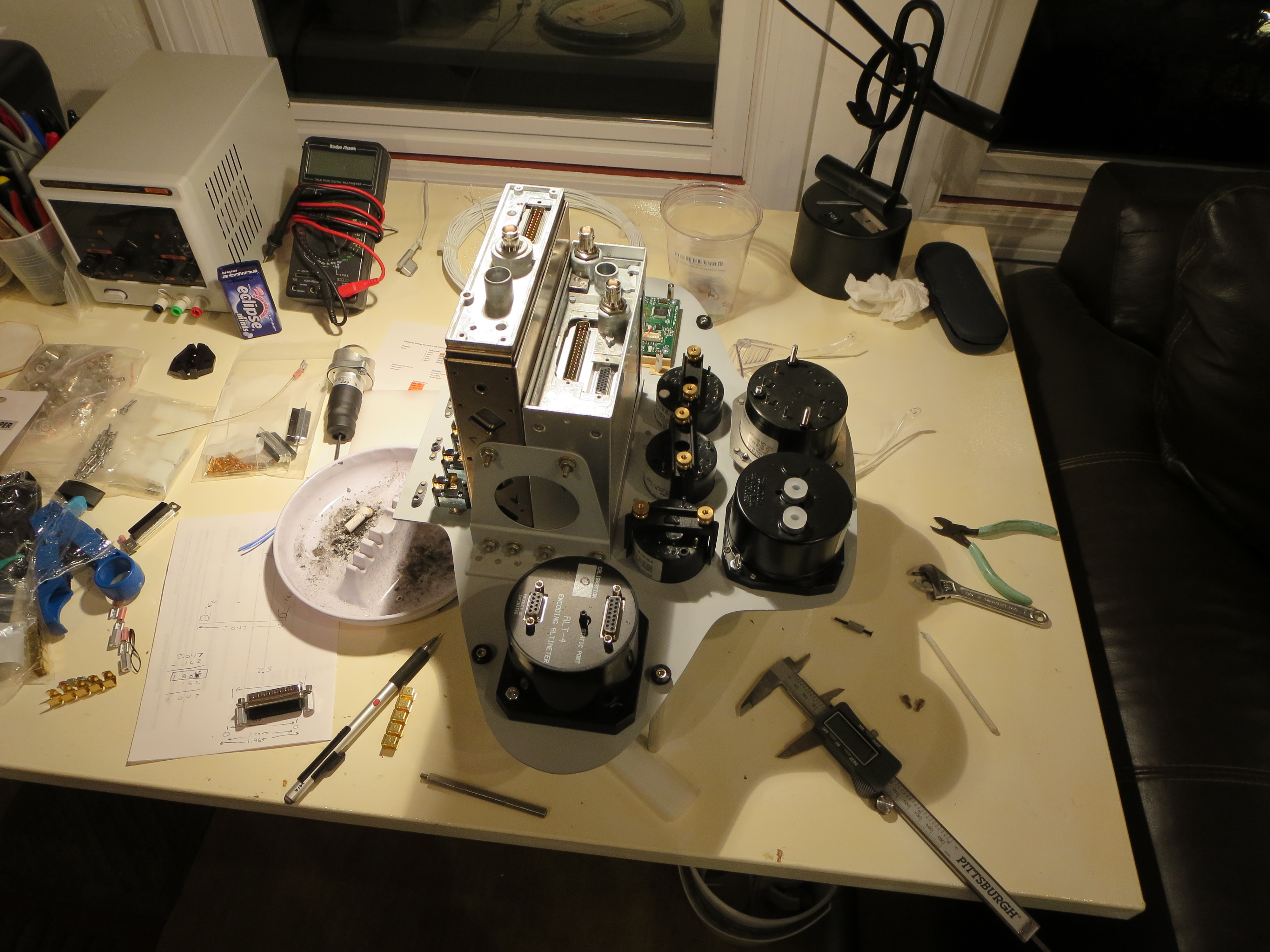
Instrument Fitting
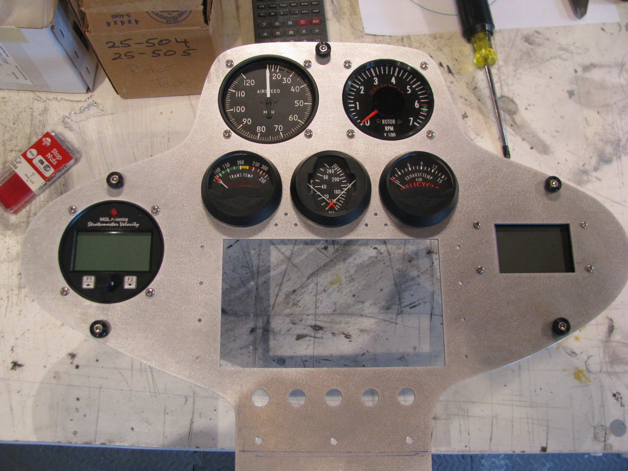
Gauge holes trimmed up and gauges fitted. I decided to fit the large gauges behind the panel just to improve the symmetry and improve the look. The square gauge on the right is my homemade digital compass.
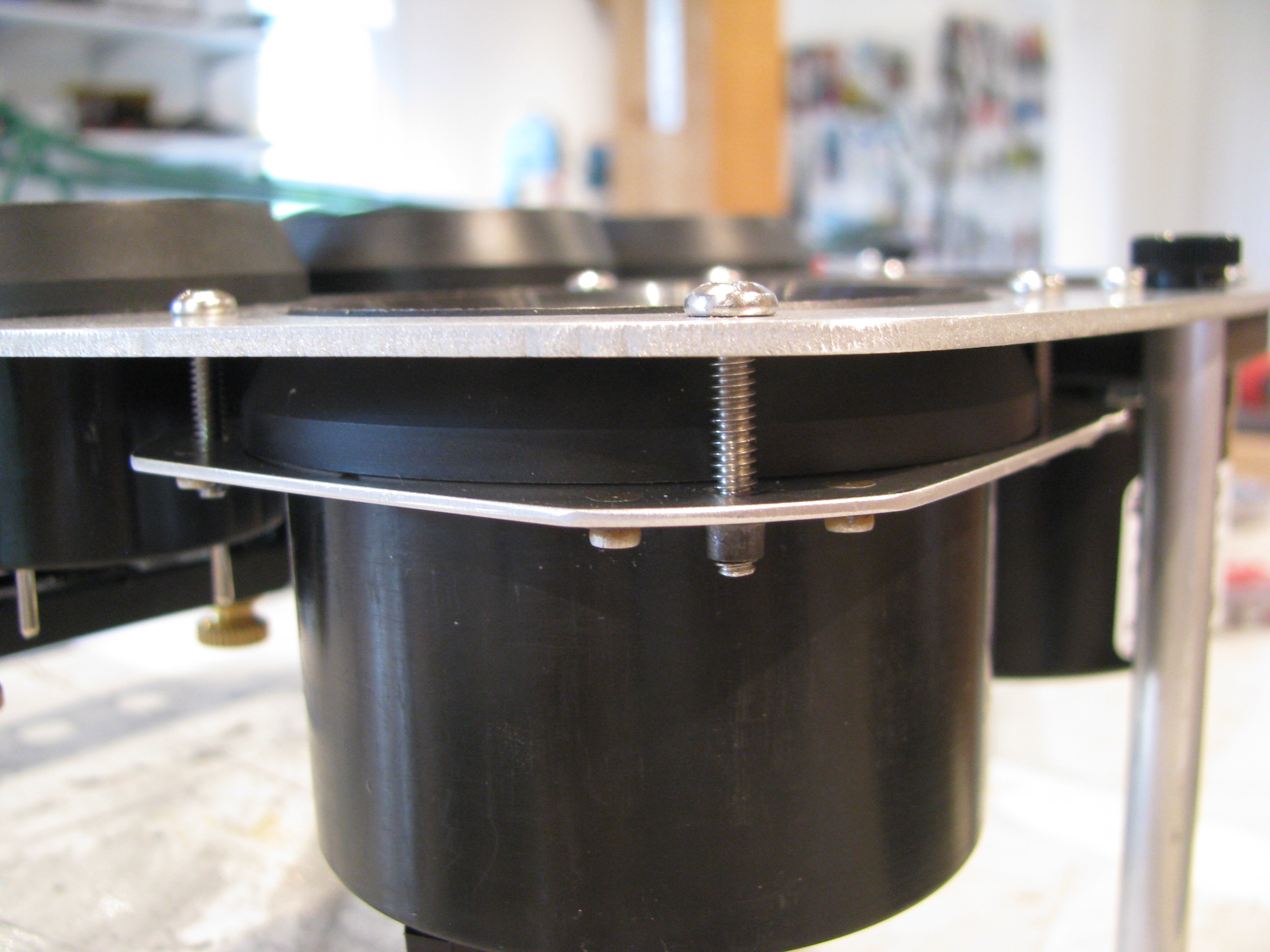
To flush mount the tach, I made this little plate to capture the gauge behind the panel. It’s really flat and parallel in spite of the camera distortion.
I am really digging having the mill with DROs. Made up a little sketch of the angles to mount the trays from the Garmin specs, measured and drilled and everything fit. The digital readouts make this operation a cinch. Also, the tolerances achievable are amazing.
Freehand, this would have required a bunch of fiddling and tweaking to get to fit. With the precision of the machine tools it basically falls together.
Mill DRO Design & Build
Clearly an accurate digital readout of the X, Y and Z-positions of the table and mill head will make jobs go much faster.
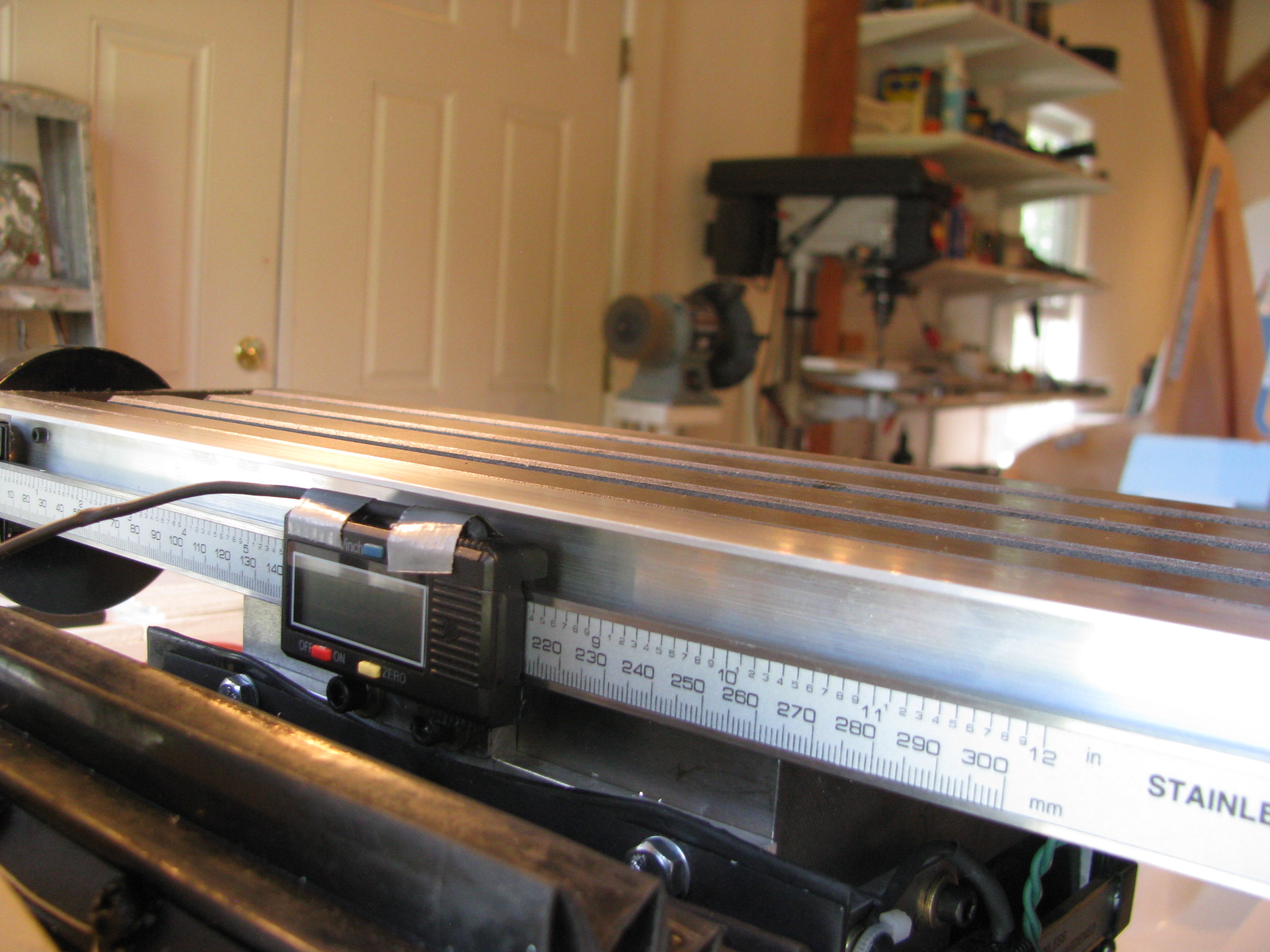
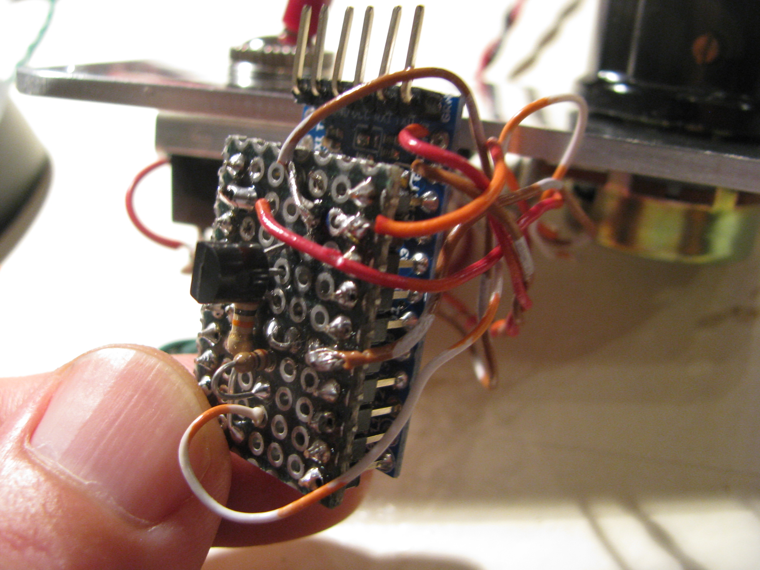
I purchased 2x12” and 1x8” digital caliper mechanisms off eBay for $24 for the 12” and $18 for the 8” respectively. I have read about various folks interfacing to those and hooked the interface signals up to a scope and observed and played around until I figured out exactly the protocol coming over the interface ports from the calipers.
For the ones I purchased the protocol seems slightly different than that measured by others. In my case the value output over the interface is simply a hex representation of the position in whatever units are selected (mm or in). One of the bits indicates the sign (it is not true twos complement), and another bit indicates the 0.0005” indication.
I whipped up a circuit to convert the voltage levels and wrote code to read the three values with an Arduino (that’s a ProMini in the center). I soldered the wires from 3 cellphone headsets (4-pin 3.5mm plugs with very, very fine flexible wires) to the caliper ports. The complete headsets were $0.99 each on eBay, which is cheaper than it would have been to buy connectors and cable and make my own. There’s $7 of buttons, connectors, passives, transistors, and regulators from Digikey rounding out the B.O.M.
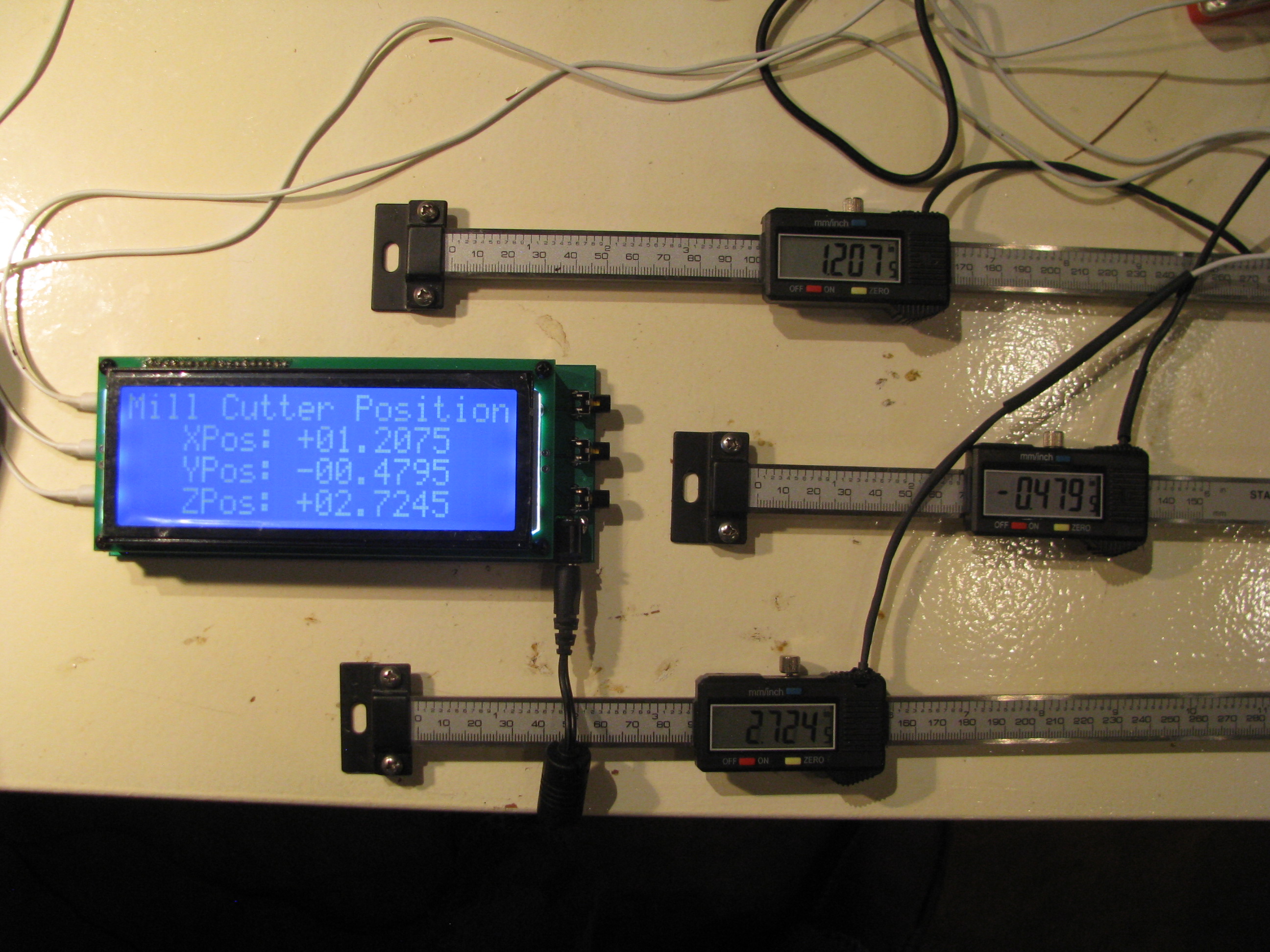
The crowning piece is a large-character 20x4 character LCD display also bought on eBay for $22.
I layed out a circuit and had it fabricated through Sunstone.com using their “Value Proto” service, which is relatively cheap. It’s mounted here behind the LCD. There are buttons on the right for zeroing out the reading on each axis independently for positioning on a workpiece.
The Arduino is clearly running at capacity to handle the three calipers worth of data. Each caliper has a clock and data line. The clock triggers an interrupt, which causes me to sample the data line on the respective port. Two of the clocks trigger the ATMega’s native pin interrupt functions and the third (Z-axis) triggers a pin change interrupt (which is a bit slower). About every 20 seconds or so one of the readings may glitch and a weird reading is indicated for one loop, probably because of a sampling error caused by the fact that the interrupts are happening right on top of each other, causing me to sample one reading incorrectly. It is so infrequent that it will not affect usage of the DRO.
Uber Weenie Alert!:
Here are the technical details of my DRO circuitry and Arduino code for my setup. If you have questions feel free to email me as the above descriptions are pretty terse:
DRO_SupportBD_sch.pdf
DRO_SupportBD_brd.pdf
DRO_Rev3.ino
LCD_Support.ino
8/10/13 - DRO Mounting and Finishing of the Mill. I bought the FIgnoggle plans, and downloaded the free plans from the Little Machine Shop for mounting the DRO scales. Then I proceeded to ignore them both since they seemed overly complicated. They might make sense if you were trying to actually read the indicator on the scales themselves, but since I have my new big display, I found I could simplify the the mounting scheme to simple plates and spacers. The only tricky one was the 6degree wedge to vertically align the Y-axis mount with the base angle. No problem - I have a mill.
Y- Axis Mounting. The sliding part of the scale is mounted to the Y-axis carriage. An 0.040” plate is screwed into the caliper’s tapped holes, then 10-24 holes are drilled and tapped into the carriage (be careful - not to deep or you’ll hit the ways). There’s another 0.25” spacer behind those allen bolts, elevating the slider. The scale is fixed to the base using the supplied brackets and a wedge machined down from 0.25” plate. Just put an elongated slot in the wedge and you can slide it up or down until it is spaced properly.
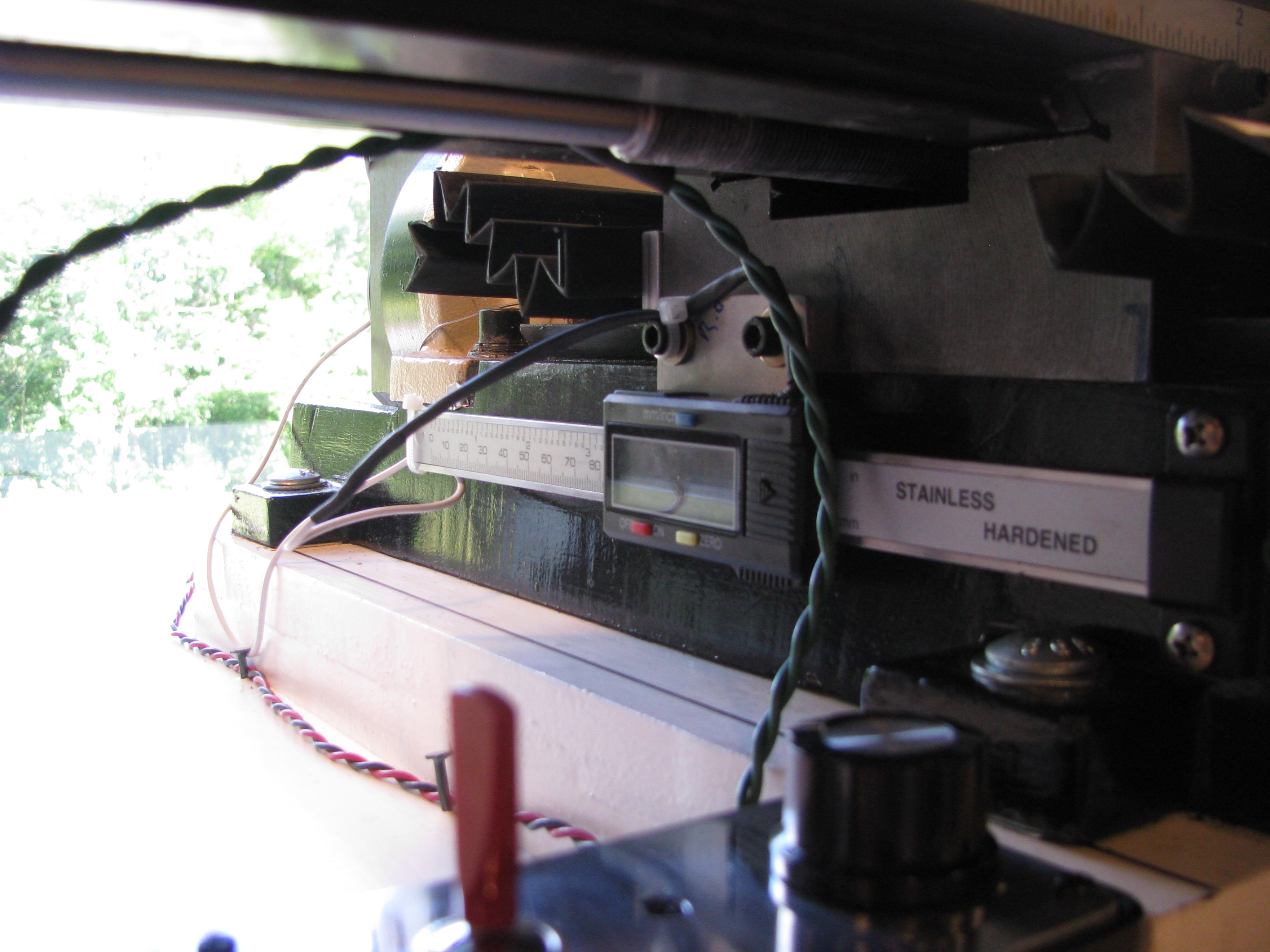
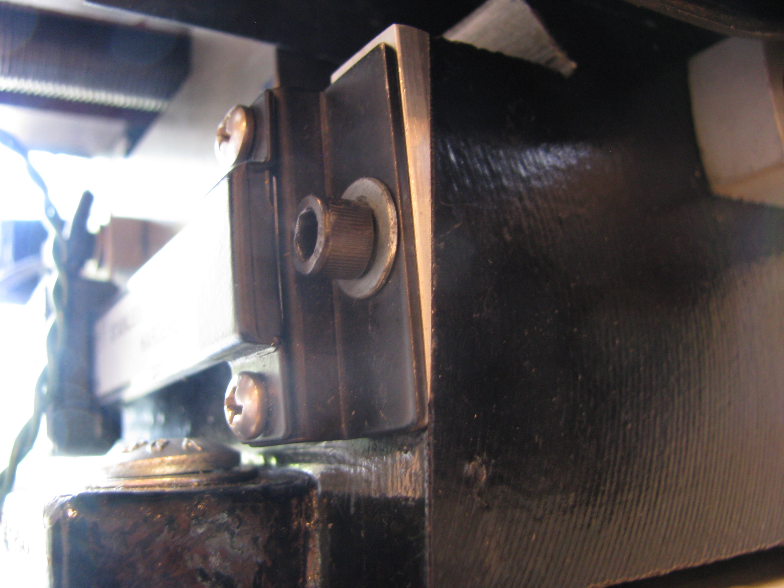
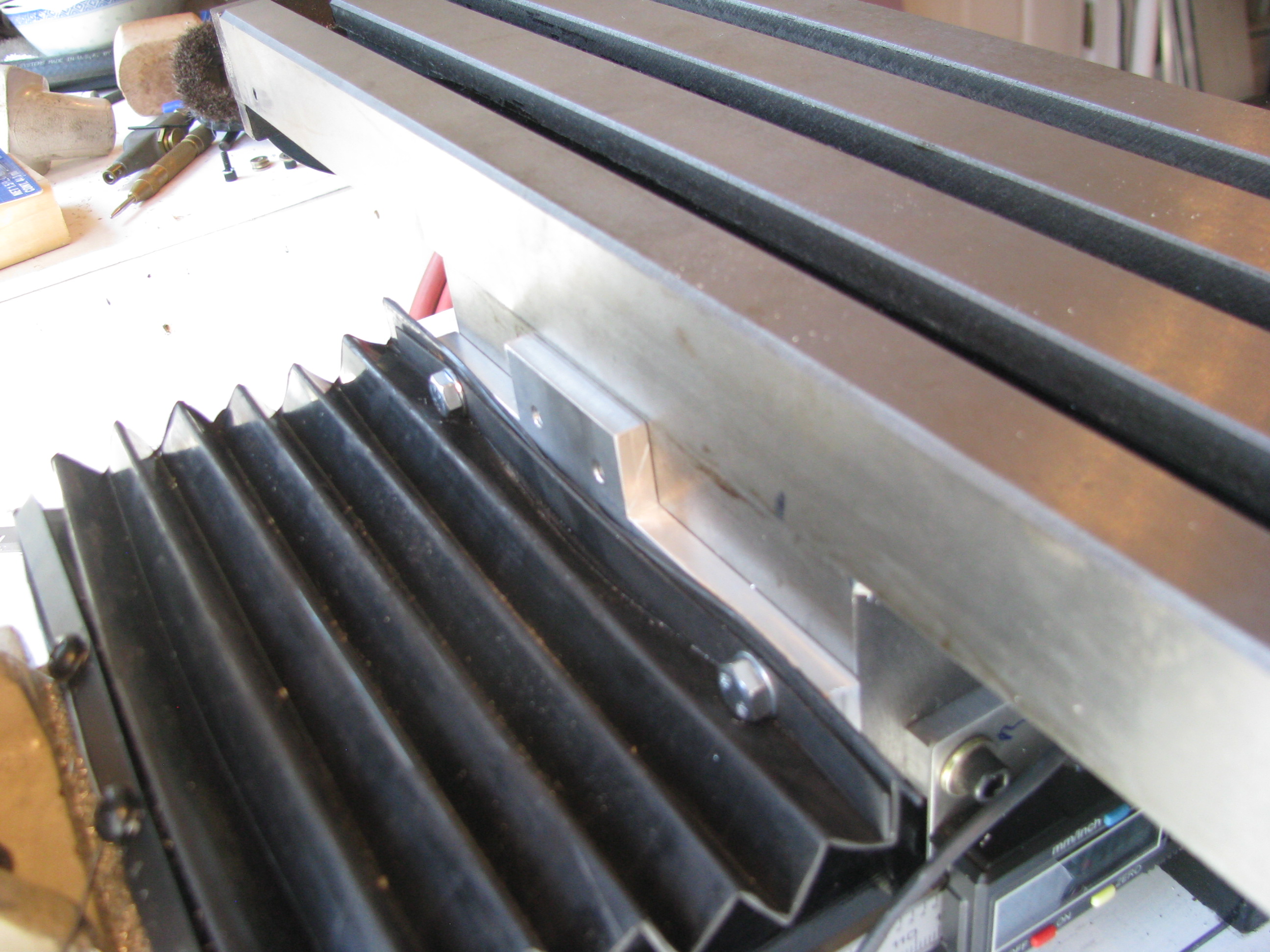
X-Axis mounting. I didn’t want the scale on the front since it would interfere with the Y-handle and the gib lock. The only tricky part was that there was no way I could drill from the back and I didn’t want to remove the column. I used the pre-existing holes for the rubber boot and machined a plate to mate with those pre-existing holes and allow for the slider plate no the caliper to screw into it. The scale is simply mounted to the table on one end. Only one hole is needed and washers (which I have many of and various thicknesses) to fix the scale to the table. The display is fixed to the Y-axis carriage, the scale is mounted ot the X-table. I then mounted a fixed angle to the table to cover and shield the scale.
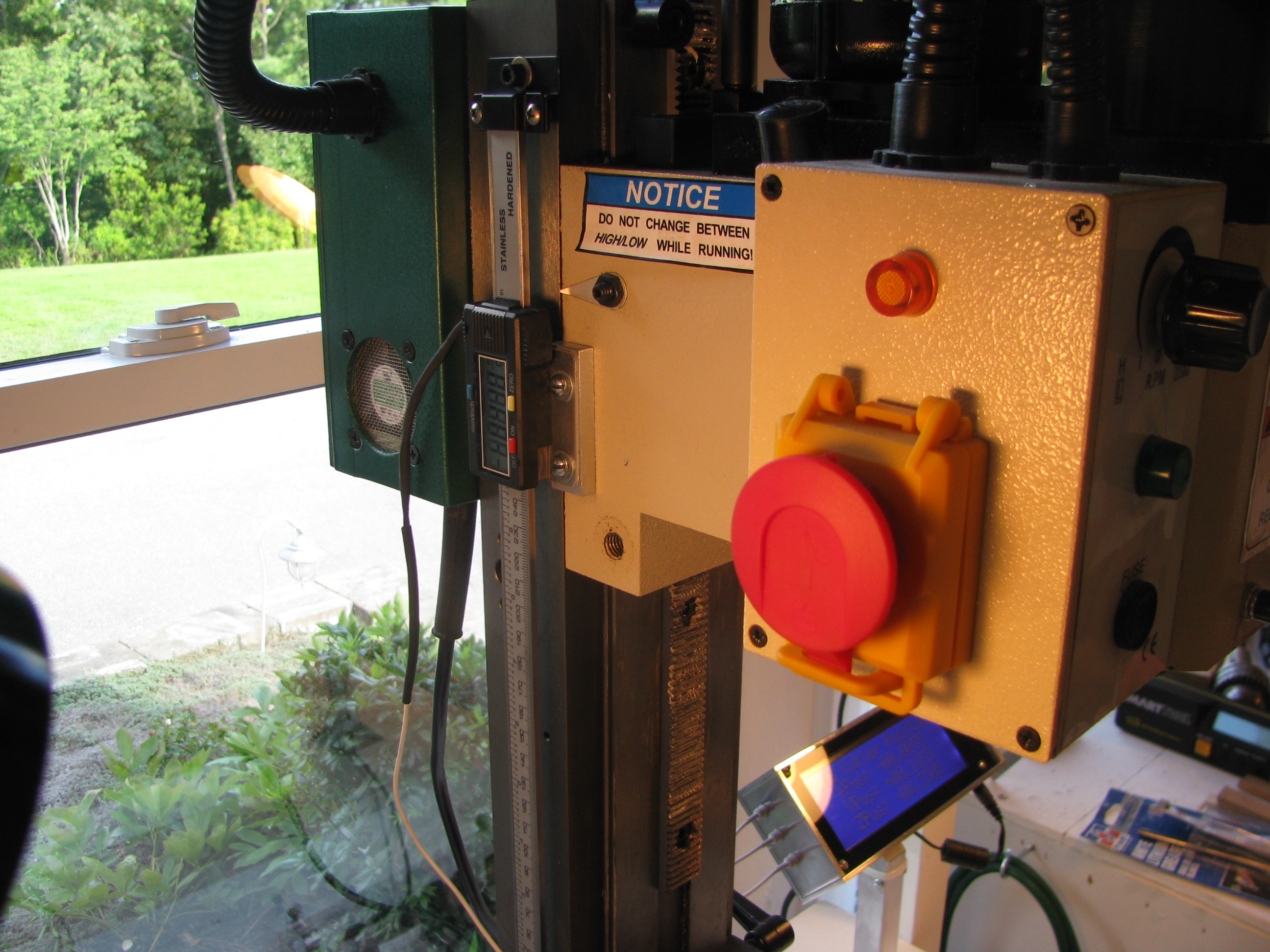
Z-Axis DRO Mount - I removed the existing visual scale (next to useless), as well as the existing spring support. This freed up a lot of room to mount the DRO scale.I just opened up and tapped on of the already existing holes on the column, and drilled two holes in the head casting for the slider. Again, an 0.040” plate on the caliper slider and a 0.25” spacer on the head casting. Simple. As before, be careful not to drill&tap too deep on the casting or you’ll hit the ways.
Other Mods - I purchased the Air Spring kit from Little Machine Shop. This provides two things; 1) A better spring, which is more linear and allows for greater travel of the head, and 2) a longer rack so that you can lower the head much closer to the table.
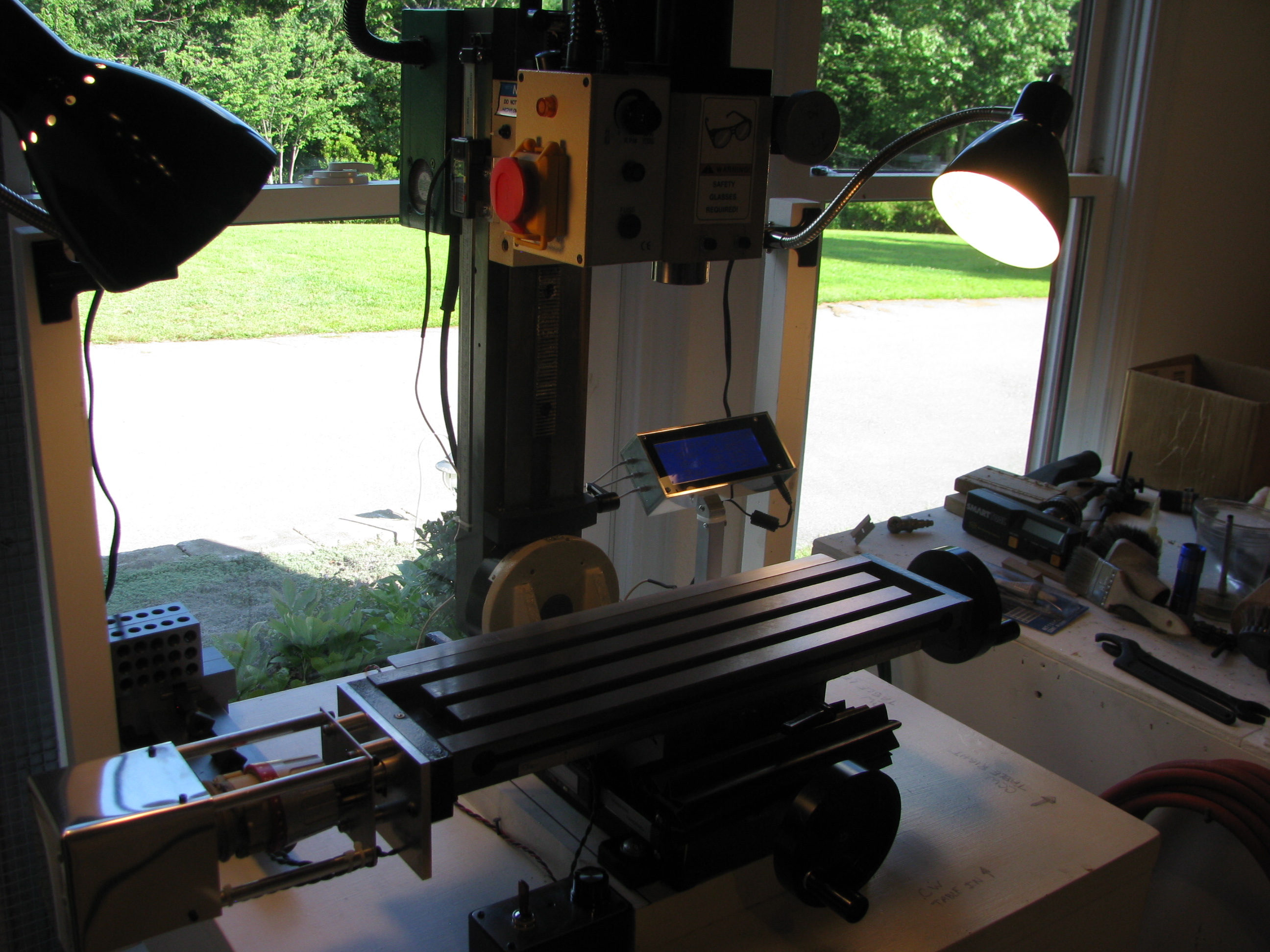
DONE DONE DONE! Now, a fully enhanced X2 class mini-mill. Extended travels on X, Y, and Z axes, a power feed, and DRO on all three axes. Nice to be completed and I learned a lot and practiced more machining technique.
Took the opportunity to scrub the shop from top to bottom and prep for the next project(s) now that this one is in the bag.
Mill Power Feed
For airplane parts it is common practice to drill parts in assembly. In this case however, I made sketches and machined all the parts to spec, being careful on all the measurements. Even though not necessary, I was able to hold tolerances to +/- 0.001” on all dimensions. Not bad for a noob. Everything fit together with very tight tolerance and no play anywhere. Satisfying.
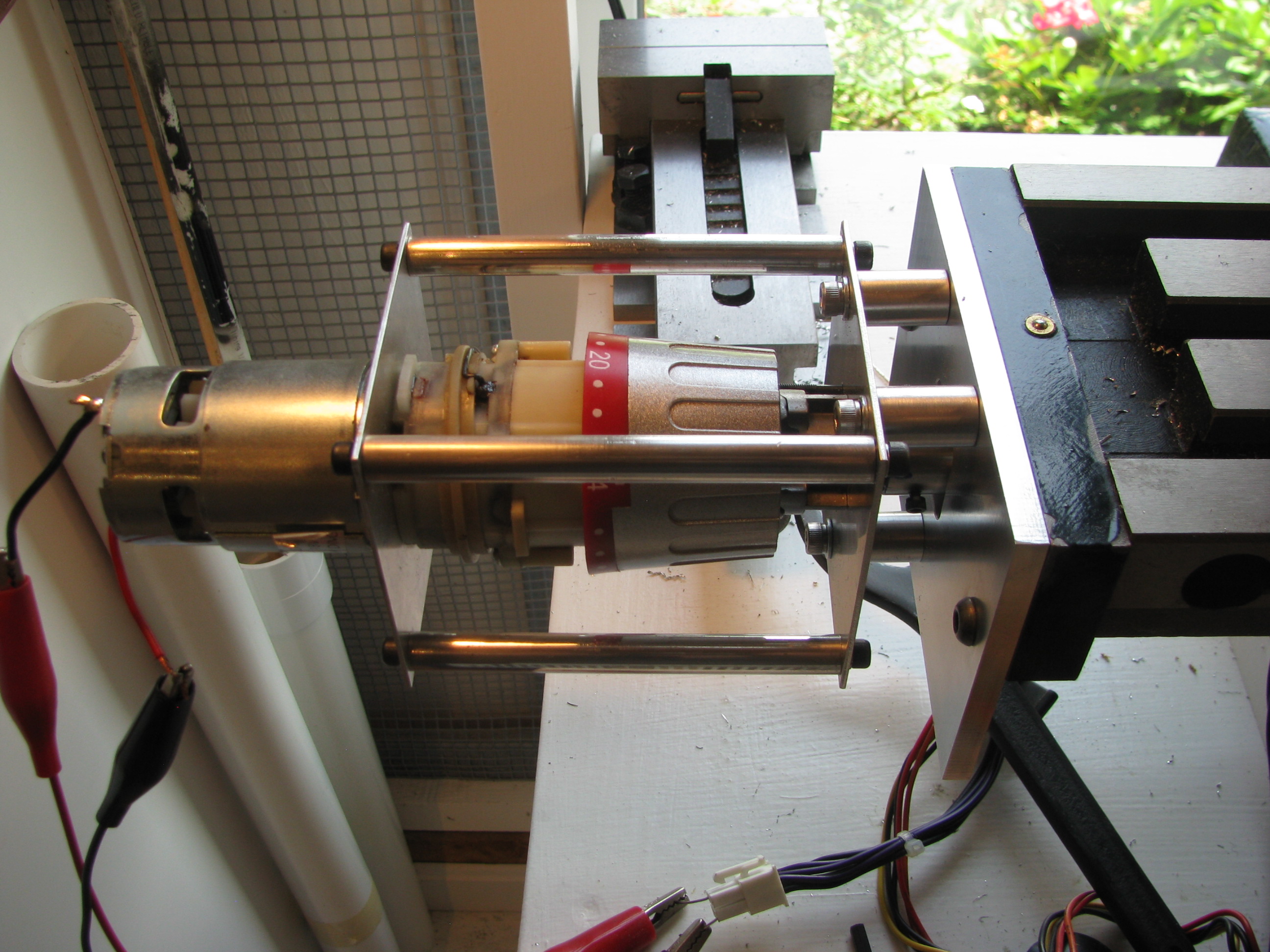
To link the drill shaft to the X-axis lead screw, I machined a coupler with a tongue that mates to a slot already present in the lead screw, and then drilled a hole through the coupler and drill shaft.
The coupler is threaded for a couple of 4-40 allen screws. When they are backed out the coupler spins freely on the drill shaft in case I want to machine without the power feed engaged. A little cumbersome and it it becomes a pain I will fit a quick-release pin instead of the screws.
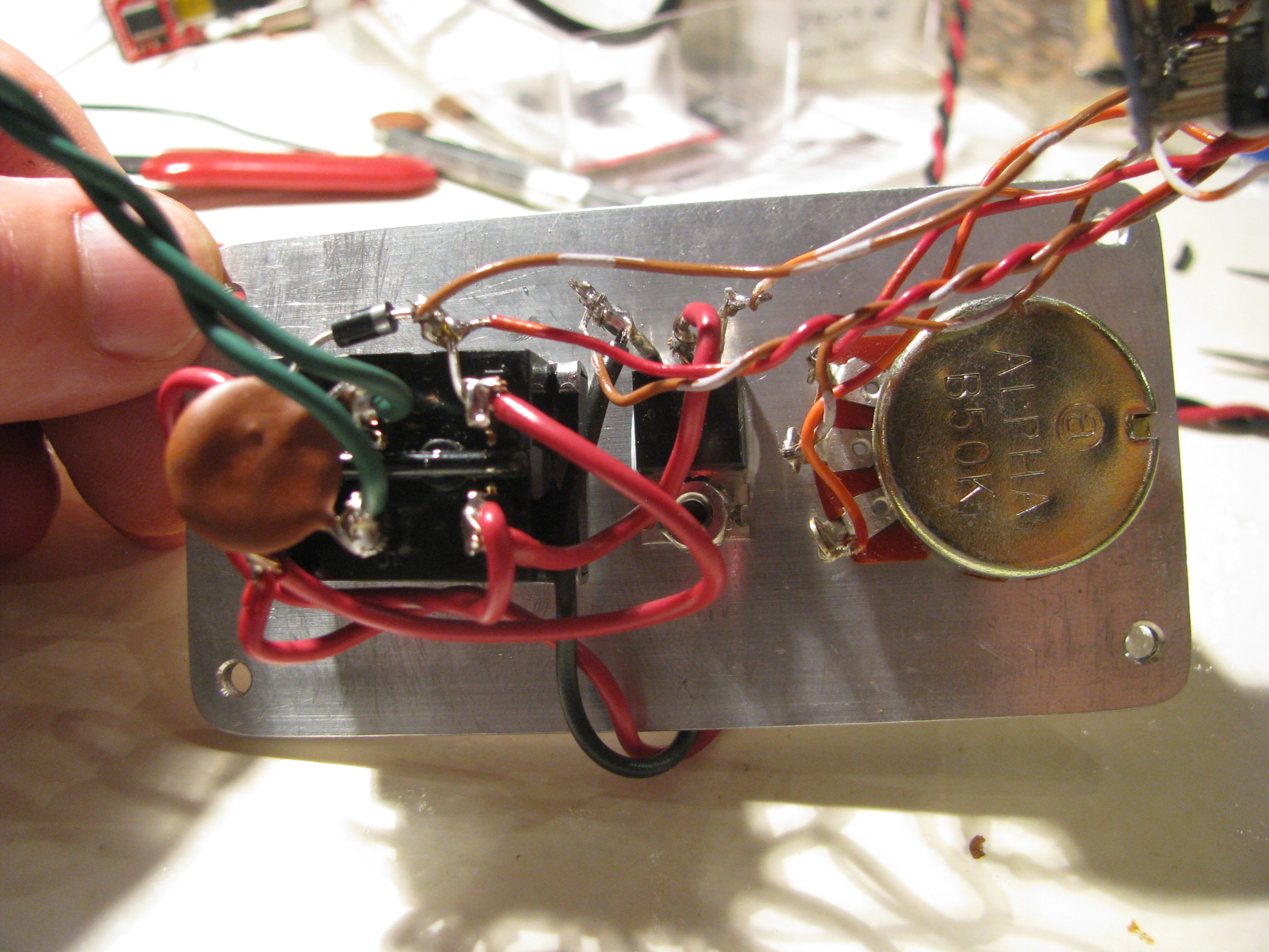
Speed Control for Power Feed. Being hooked up on the Arduino, I whipped up a little PWM program. It reads the voltage on a linear pot and adjusts a PWM signal output width. I just used a DPDT-Center Off switch to change direction and turn it off, so the Arduino’s job is simple. Just read a POT, adjust the PWM pulse width and drive a power FET (IRFZ44). A little Radio Shack Project box with the aluminum cover replaced with a 0.125” plate machined to accept the switch, POT, doubles as the heat sink for the FET as well. Works great.
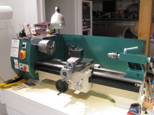
Milling Machine

About 3 years ago I invested in a Grizzly G0516 Lathe/Mill/Drill. The lathe is great. Very capable. The drill very precise. With patience you can drill very accurate holes. Milling left a lot to be desired. It took a lot of setup and then the machining was tough with the small mill table and relatively imprecise control using the lathe slide as the table movement control.
On paper it sounds great, but like many before, I have realized its limitations and really only used it for milling maybe 4 or 5 times seriously.
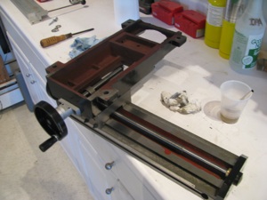
Little Machine Shop (.com) offers this milling table (shown here upside down). It is a little larger than a Sieg X2 table and the G0516 milling head bolts right to the back, effectively making a big-table X2 mill.
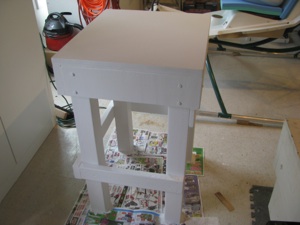
Step one is to fabricate a sturdy table made to fit in the only convenient spot left in my shop (too many projects). 4x4 legs, 2x6 table stringers, 3/4” ply and 3/4” mdf forming the top with 3 or 4 coats of urethane to seal it all up.
Everything is screwed and glued to keep it as stiff as possible. The surface is true within 0.1degree (I love my digital level).
As with the lathe, the first step is to take everything apart, clean off the shipping grease, and check all the surfaces. It felt pretty bad right out of the box - very sloppy movement - alternatively too tight and too loose with lots of side play.
That shipping grease turns to something like chewing gum and some of the sliding surfaces had paint on them. Don’t even think of using these Chinese machines right out of the box.
But as with the Grizzly, after a little work the motion cleans up, smooths out, and the tolerances can be snugged up substantially.
Virtually no play on the table movement once the gibs are adjusted. The motion is kind of stiff. After some use I may lap the ways and gibs to smooth it out and allow freer motion.
Complain as folks might about the Chinese machine tools, the value per dollar is amazing.
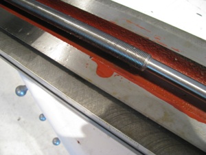
I don’t have any pictures of my tramming - my first time doing it with any precision. It took hours. I first made a tool I could chuck up in the mill that rigidly held my dial indicator 3-4 inches off centerline.
The Y error was about 9 mils at the start. This is the fore/aft “lean” of the mill column. To adjust it you unbolt the casting that holds the giant column mount stud, tilt it the appropriate direction and add shims to the appropriate side. Very thin shims. Doing the trig showed that I needed 2.5-3.5 mils of shim. My thinnest shim stock is 5 mill brass, so I ended up using aluminum foil. Lightly grease up one side (so it sticks) and layer it together. I needed a strip about 3 layers thick to get the Y tram. Since aluminum is not the strongest, I will have to check this periodically.
Since the column is designed to tilt left and right, it is just a matter of loosening the giant bolt and tilting/bumping the head until things are accurate, then snugging it down.
I ended up with about 0.5 mil Y tram error and just less in the X. I only have a dial indicator, so this is all probably within the error of the indicator, but sufficient for anything i will need it for.
Interestingly, the Jacob’s chuck had about 1.5mills of runout (since I was measuring stuff anyway). When I switch to a milling collet I will check the runout of that to see if its the chuck or the spindle head (I hope it’s the chuck).
The lathe denuded of the milling head. Whenever I needed the lathe it seemed I had t set up to drill and vice versa. This new arrangement should be much more efficient and I will be more inclined to use the mill for precision drilling instead of the old drill press.
Next up is to add my DRO indicators to the mill table. I’m going to make some chips first.
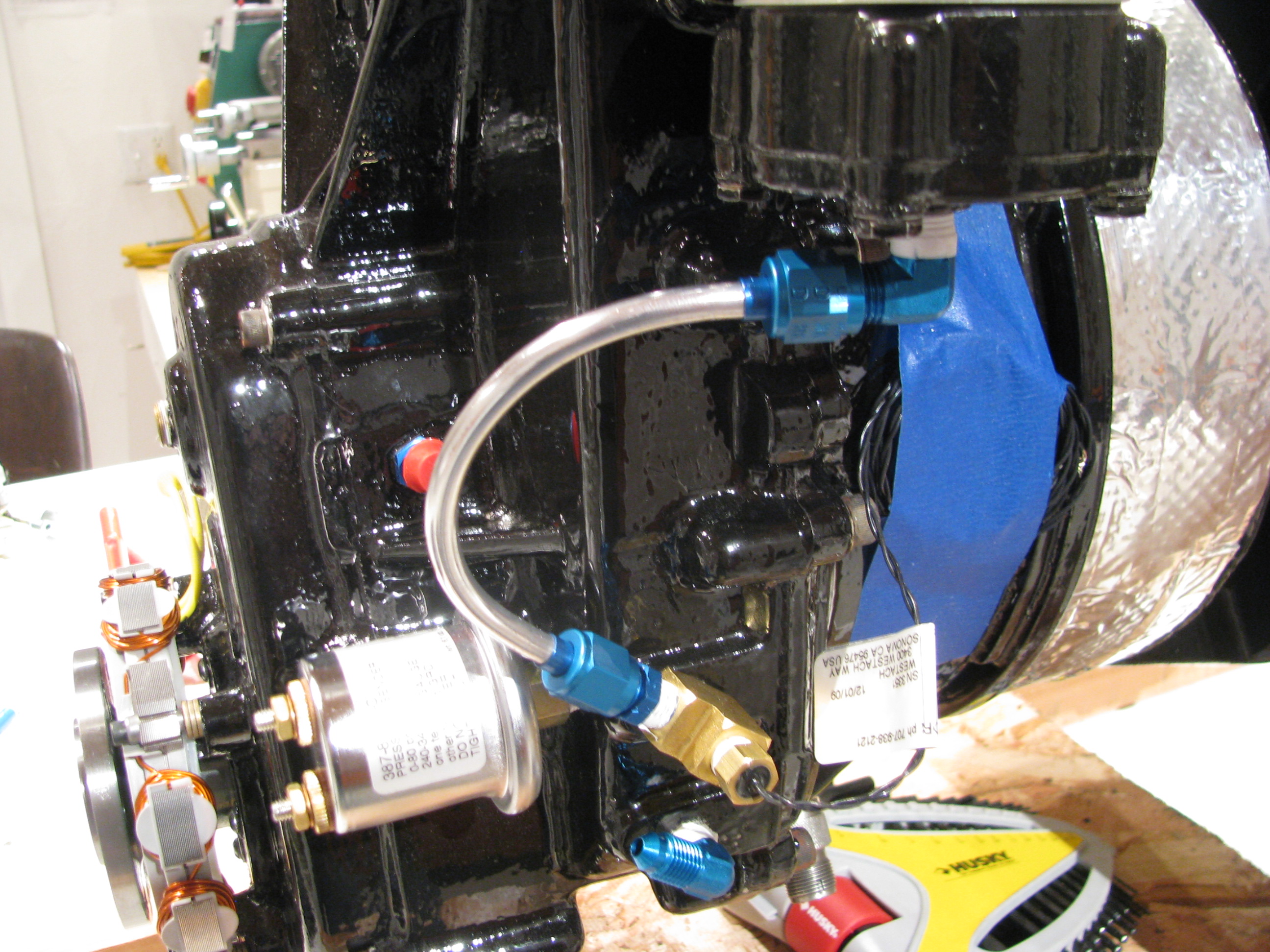
Turbine Plumbing Done
Completed plumbing of the engine oil system.
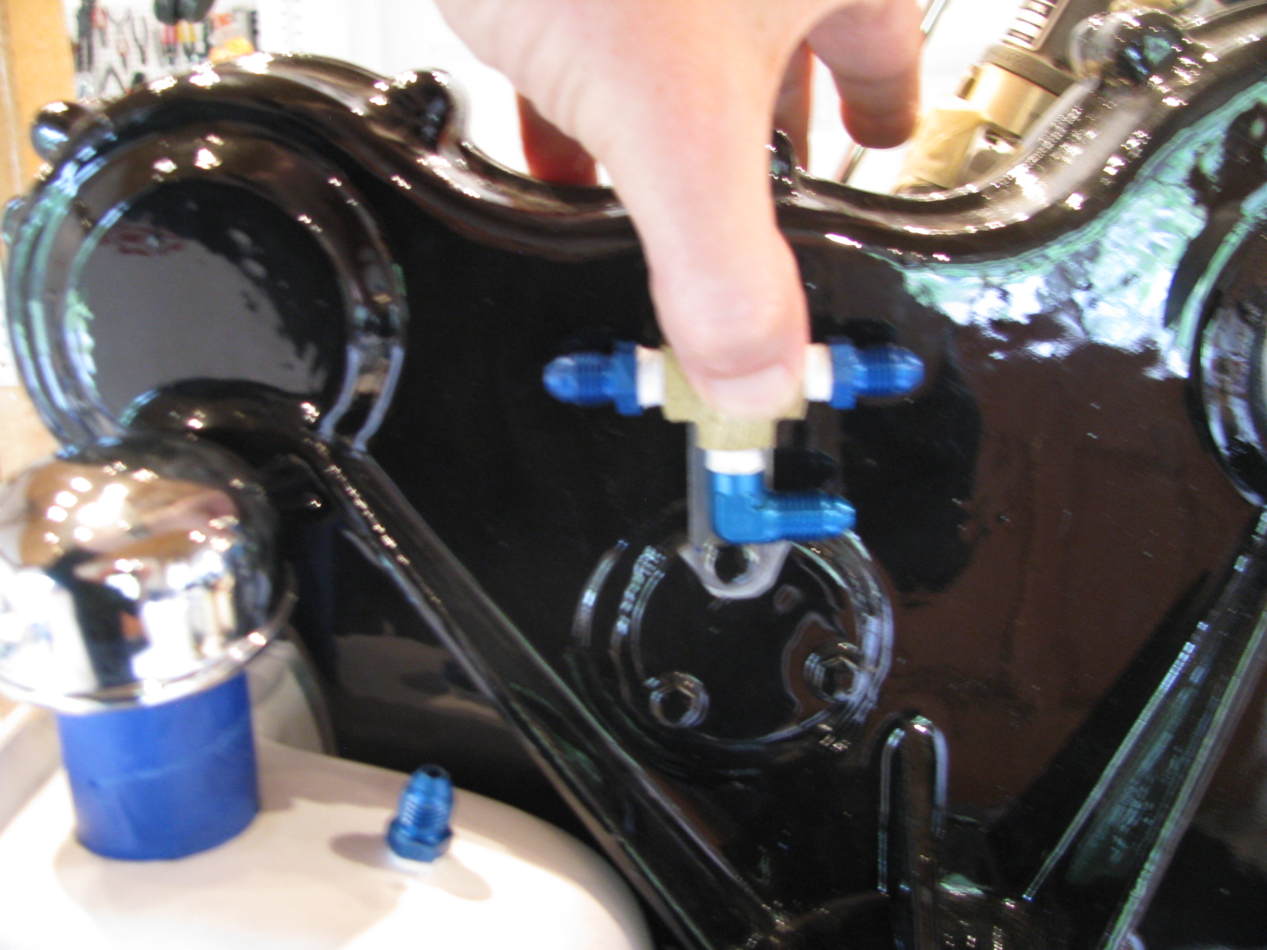
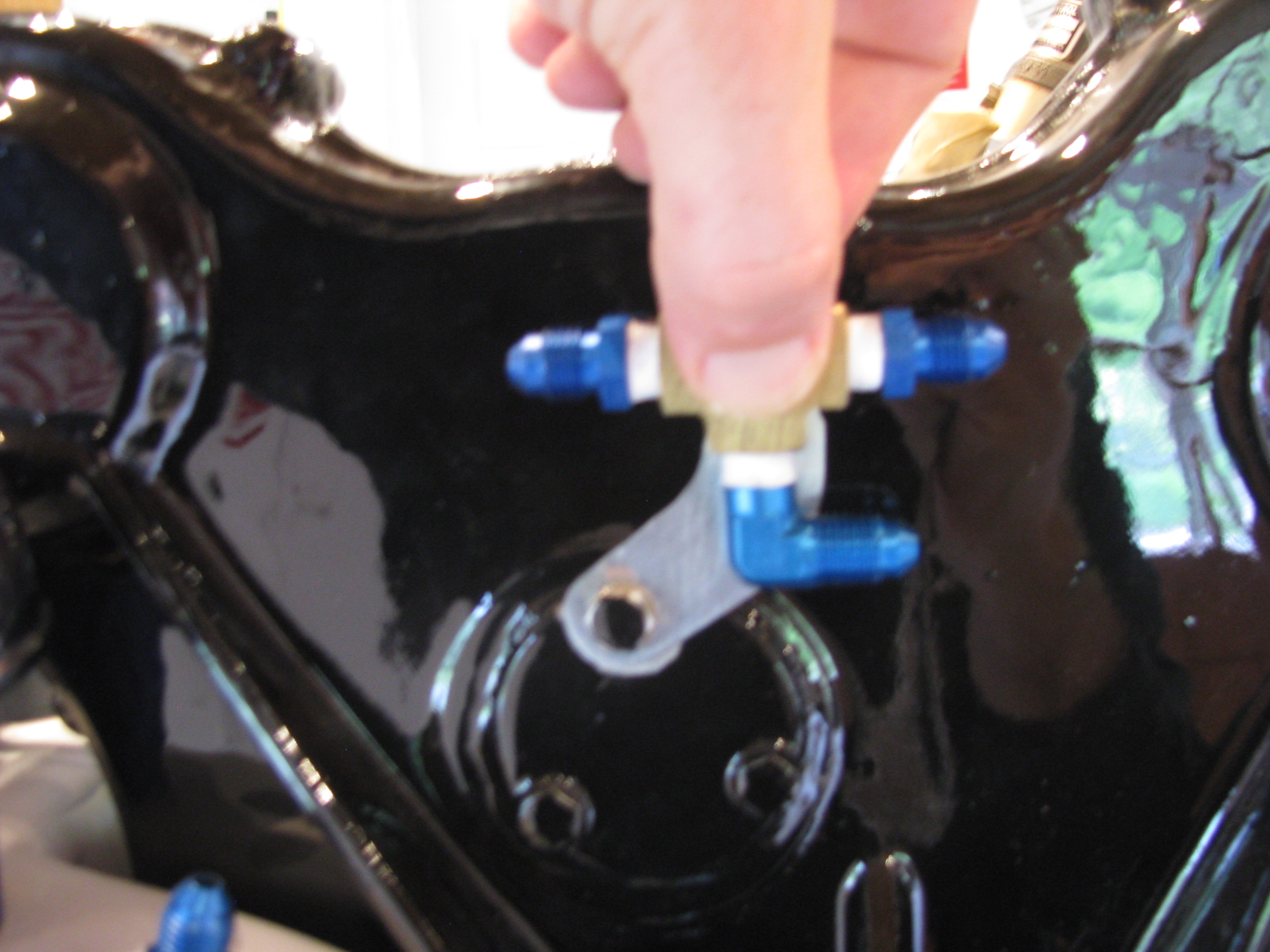
My tubing flare tool clamps just about an inch of tube, so you can’t begin a bend until then. I found it easier to offset the central Tee about an inch to be able to make the line from the top of the tank possible.
The top bracket is per BJ’s instructions. The lower one is bent for the actual offset needed so the bends were not too tight.
The money shot. Doing the tubing is a pleasant project. Try the run with wire first for test fitting, cut the tube, gently coax it into shape, polish, flare (don’t forget to add the fittings first - done that), and it all comes together. My son’s girlfriend said it looks like some 50’s science fiction movie prop with all the gadgets and tubes.
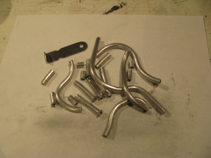
I don’t know if anyone else has the problems of a lot of scrap. This being a trial and error kind of thing I ended up with a lot of little pieces like this. I had to actually buy more Versatube from A.S.&S. to finish my job.
I got enough to make BJ’s “poor man’s oil cooler” should it be needed. I will try without first as I am in a chillier climate (especially this year). I’m not a fan of blocking the inlet airflow.
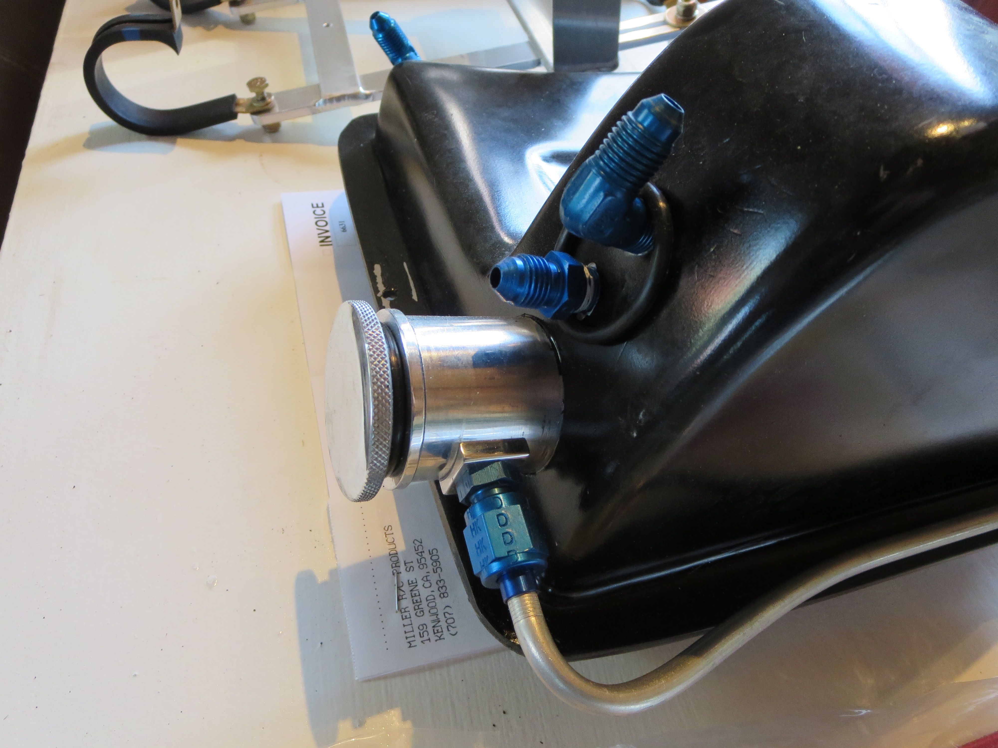
Oil Tank Fab
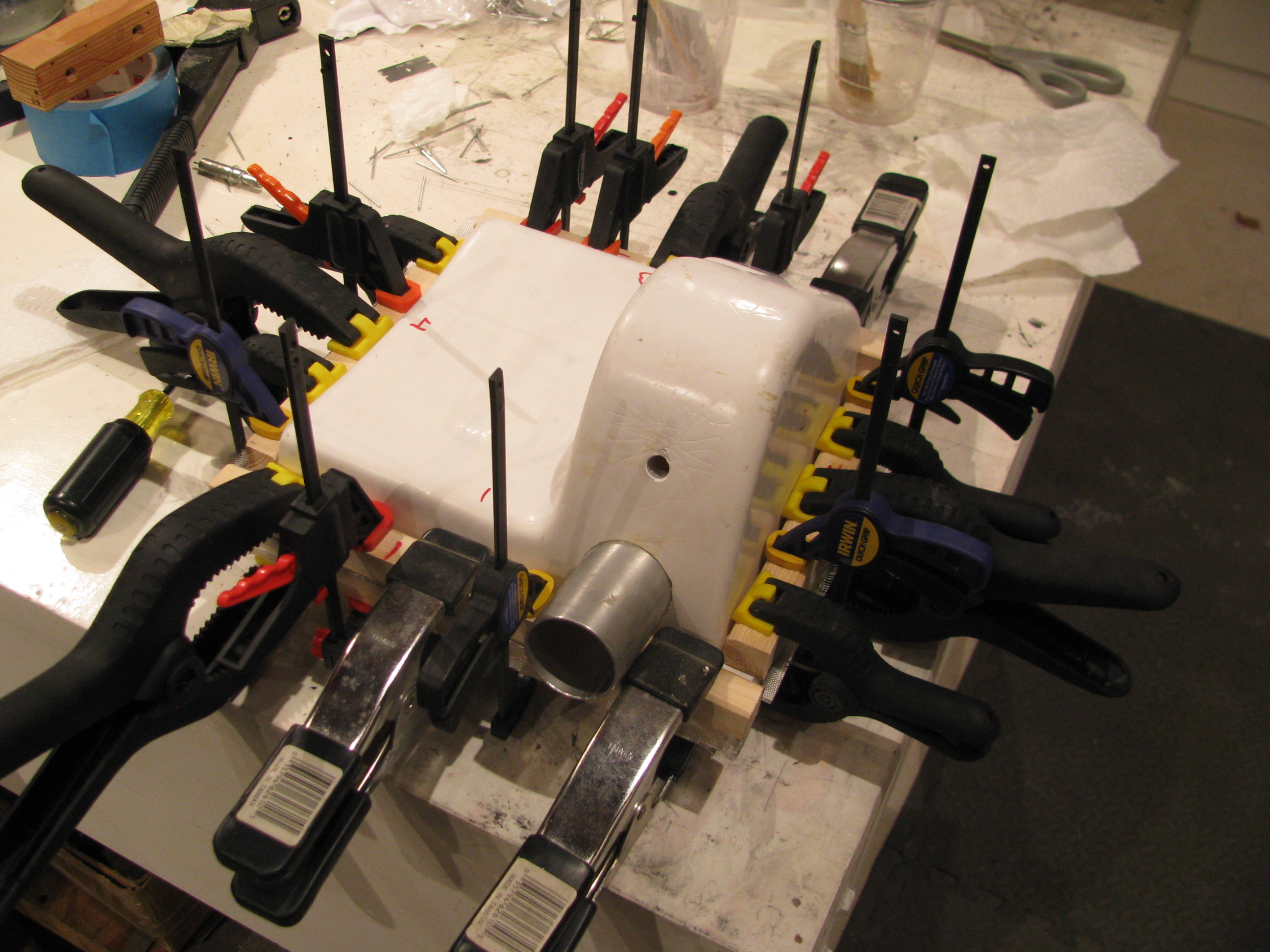
Fiberglassing together tank halves. Tidy up the insides (some stray bits of glass and cloth needed trimming, clean the surfaces with acetone, and bond the sides with a thick mixture of flox and resin.
Check for extrusion out each edge and clamp the hell out of it.
The tank mount brackets. You can see my many trial cardboard templates.
Thankfully I had an old ZVBox case that was 0.048” steel which I could use as a donor since there really isn’t enough steel strapping supplied to make the brackets, especially in the weird shapes you actually need, as opposed to the nice straight ones that BJ shows.
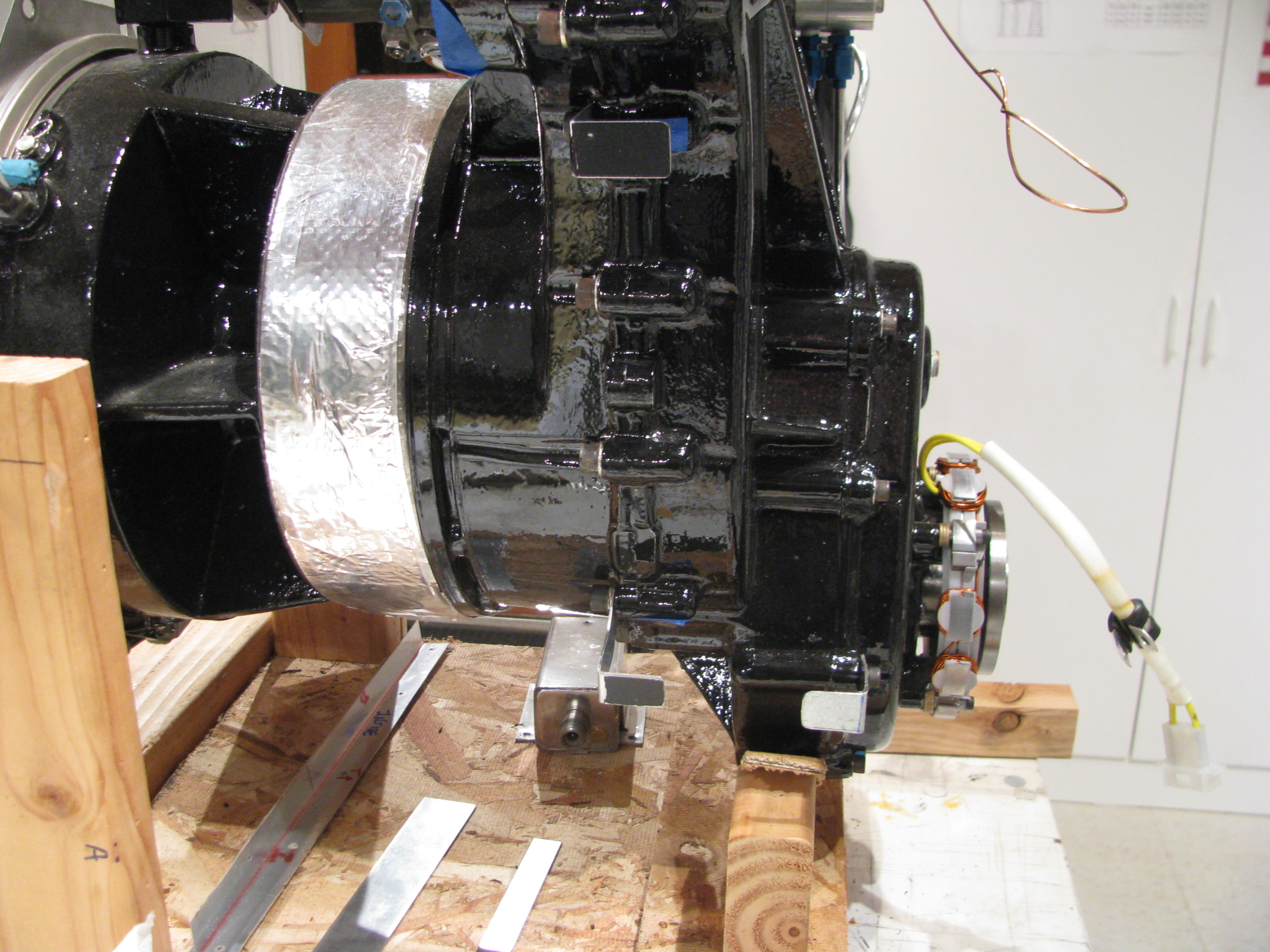
The videos show only two mounting points, top and bottom. I added a third using the one of the lower forward case bolts as the mount point. This takes it from something that could vibrate with some play to being very, very rigid to the engine.
There are a few points in the instructions like this, where it seems a very simple mod can add immensely to the strength/quality. I am sure I’m not the first to do this.
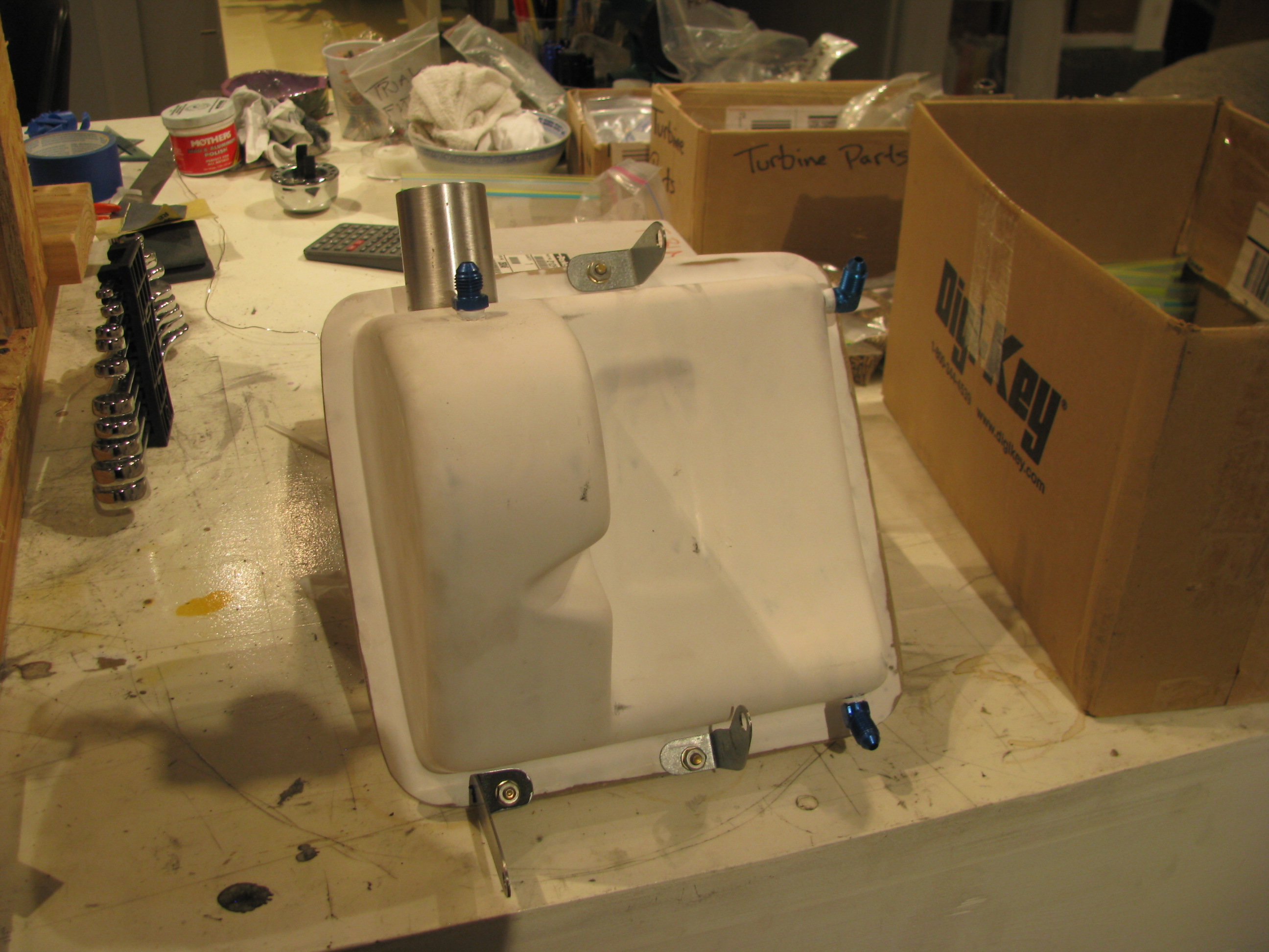
Finished tank with fittings mounted. I glassed the tank in the fall, but only just now finished mounting it this spring. My long winter of distractions, international travel, and business has ended and I plan on making very good progress on the helicopter again.
Panel Cut & Delivered
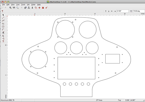
Panel Received. I discovered an online service called eMachineShop.com
This service will take a simple drawing and machine up a part for you. My method is to model the item in a “real” CAD system (in my case SpaceClaim), then import the drawing into their proprietary tool. You could do all your modeling in their tool, but it’s pretty primitive and yet another tool to learn. Select the material, and once it passes their design rule checks submit the part. A week later you get the item delivered. My panel cost me about $95 in 6061-T6 0.090” aluminum. I wanted some beef on the panel thickness to avoid having to add support structure for the planned avionics.
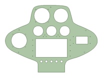
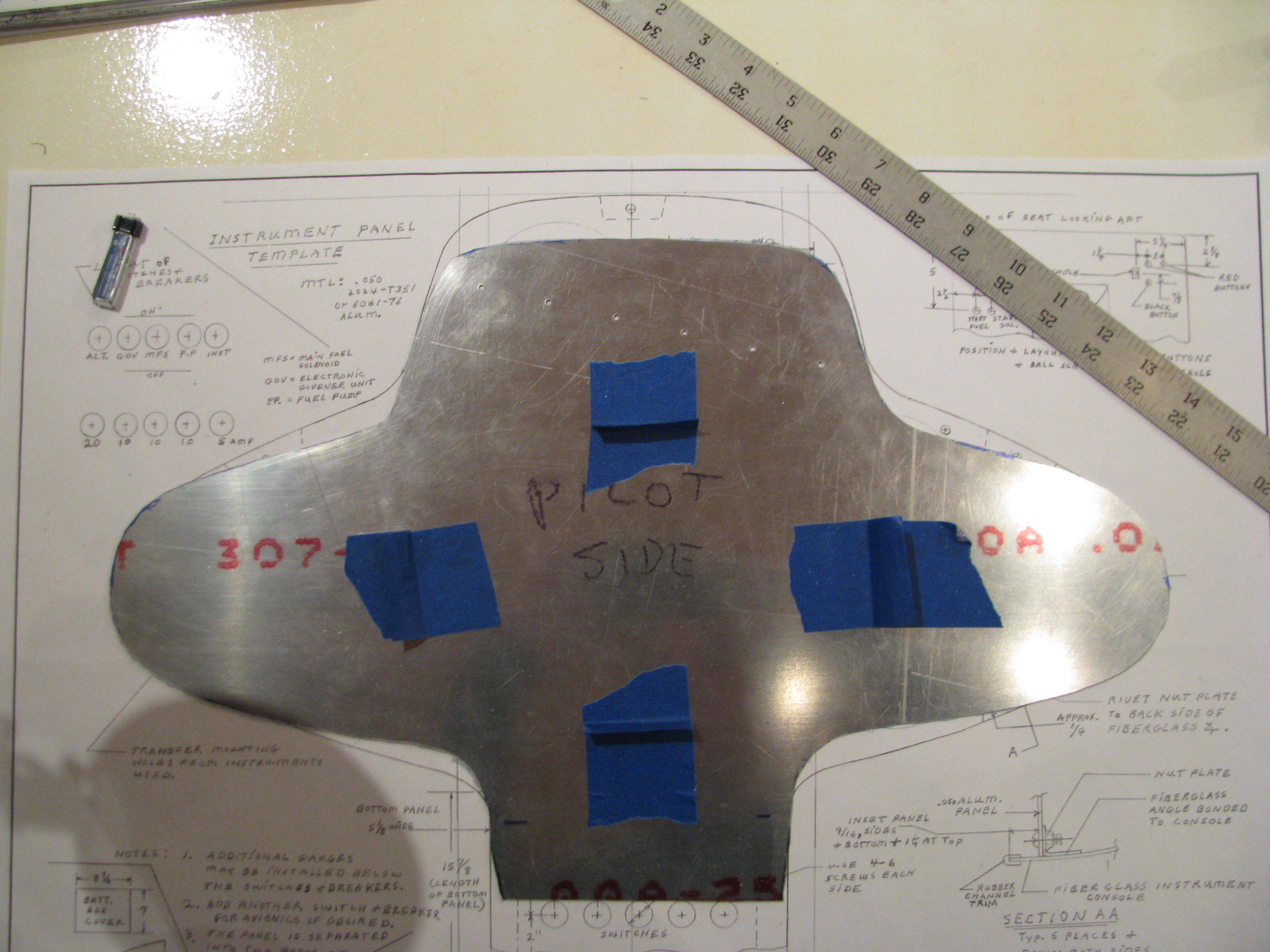
I took my aluminum “test fit” piece, traced it on graph paper, measured the points, and splined up the outline. Then I rough-modeled the instruments, shuffled them around and “cut” the holes. Everything is tight or slightly undersized so I can trim for a nice snug fit. As BJ says, it’s easier to remove metal than to add it back in.
And here is the finished item. It was returned in just over a week and fits perfectly. Some of the holes need trimming, but that was expected as I wanted a nice snug fit.
Here are the links to the rough DXF’s of my panel that I used to import into eMachineshop’s tools:
PanelMock1.A.dxf
LowerPanel.dxf
Compass Bug Killed!
Experimentally I found that my lab supply was the problem. The HMC5883L must go through some internal initialization at power up. I have a big honking lab DC power supply. Whenever I turn it off and on I get a relay click and a big hum - must be charging some caps or something. Anyway, when that occurs the compass chip must latch onto some stray field being put out by the supply which screws up its internal power-up calibration routine. Certain relationships and distances between the compass and the supply proved to be worse than others.
Using a different supply, or just a separate switch from the lab supply’s switch got rid of this behavior. Nice to have it understood/killed. My experience is that if you have a bug on the bench, even a very rare one, it will occur in the field - probably at the worst possible moment.
Electronic Compass
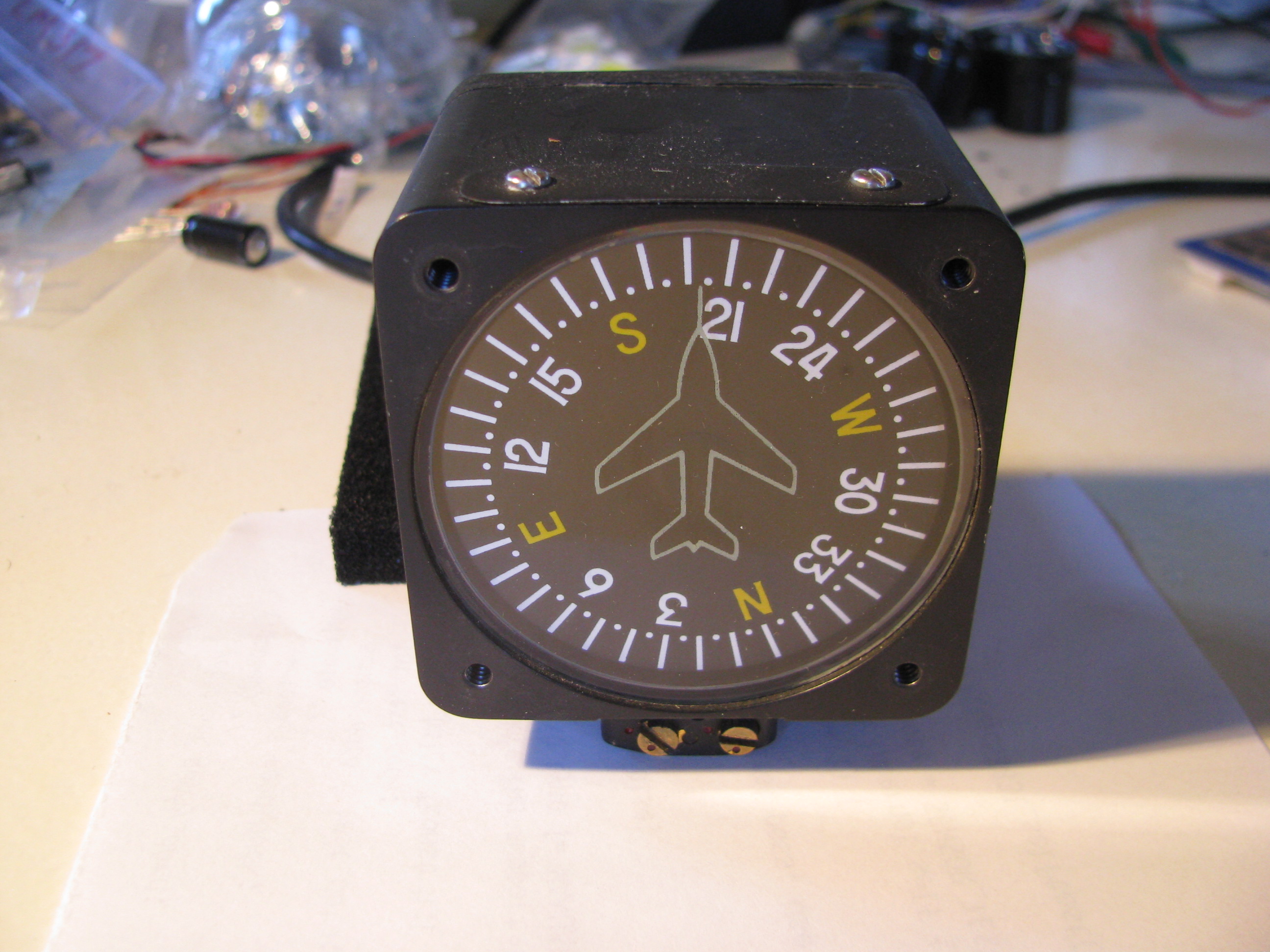
Every aircraft seems to have one of these, so I just assumed I should get one as well, so bought one from Wentworth on eBay for about $200.
It’s awful. Sticky motion and inaccurate (+/- 5 to 10 degrees). Now this one is used, and does not work as well as the one in my plane, but - damn - there has to be a better way to tell direction than sticking one off these butt -ugly devices on the top of the instrument pod.
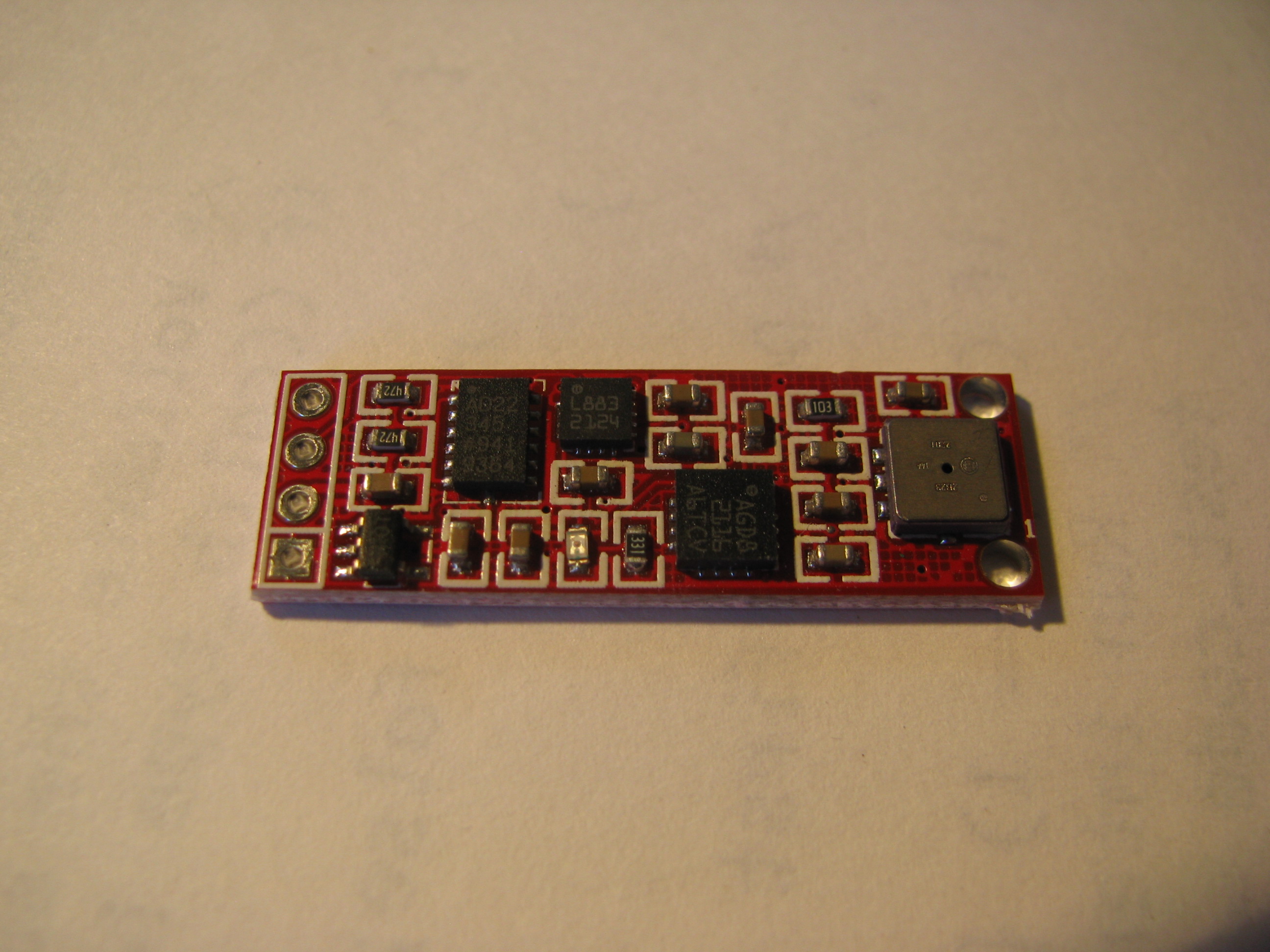
Looking around the web revealed these little gems. This is basically an inertial navigation system on a little 1.5cm x4cm card.
Onboard there is a compass chip, a 3-axis accelerometer, a 3-axis rate gyro, and a barometer that tells temperature as well. All this for <$20.
Seems like one should be able to build a compass out of this pretty easily.
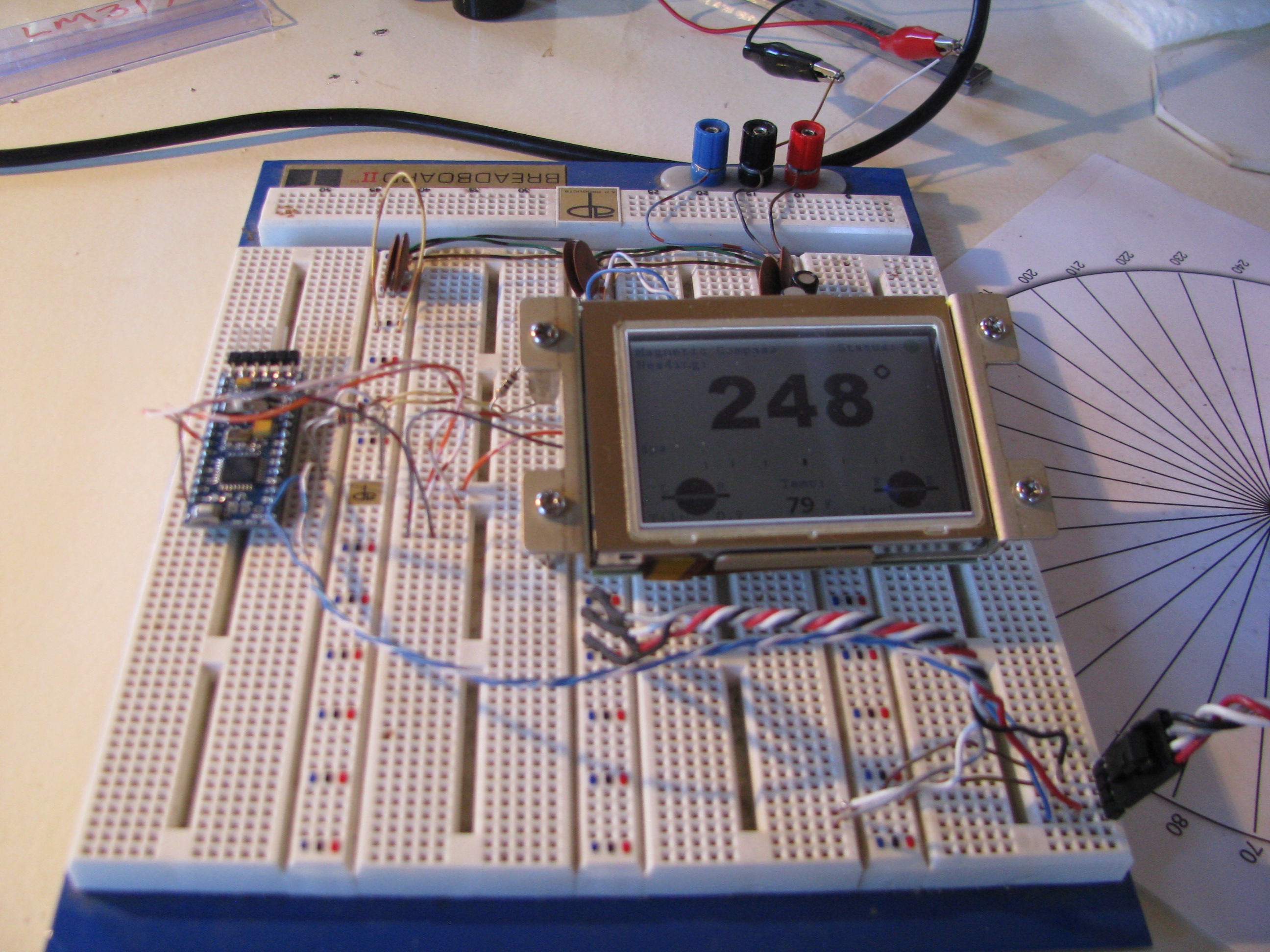
I took the opportunity to learn about the Arduino. Neat little micro - fairly self-contained with a well-developed open-source IDE. That‘s a sunlight readable LCD from EARTHLCD.
The display is driven by a serial line from the Arduino and the IMU module is interfaced via I2C. All-in-all some very simple wiring to get the whole mess working. Of course this will all get packaged up cleanly before installation for real.
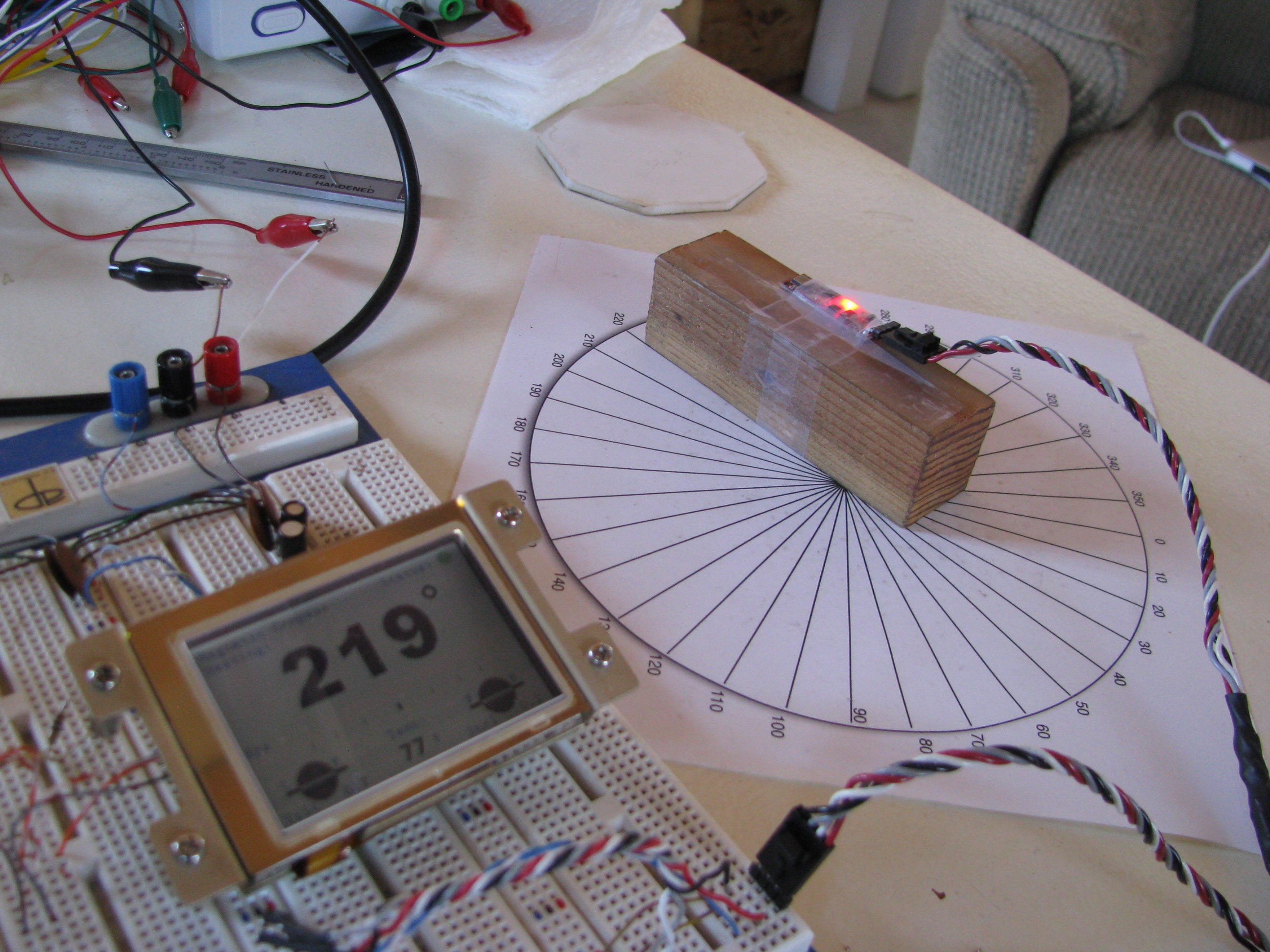
The test jig. The rose is calibrated with a fluid compass to point North. The IMU is just taped to a block of wood. It’ll be mounted up in the nose of the instrument cluster pod.
I learned a lot about the earth’s magnetic field and compasses. I did not realize that the primary magnetic force vector points 70 degrees downward at my position on the planet.
What that means is that the compass works well if level, but is WAY off if tilted by even a degree or two. The solution is to use Z-axis of the magnetic field reading and the accelerometer to detect tilt. Then do the 3-D vector trigonometry to correct and compensate for the tilt.
All of this is a lot of math and was a good challenge. It’s been years since I did matrix operations and lots and lots of trig.
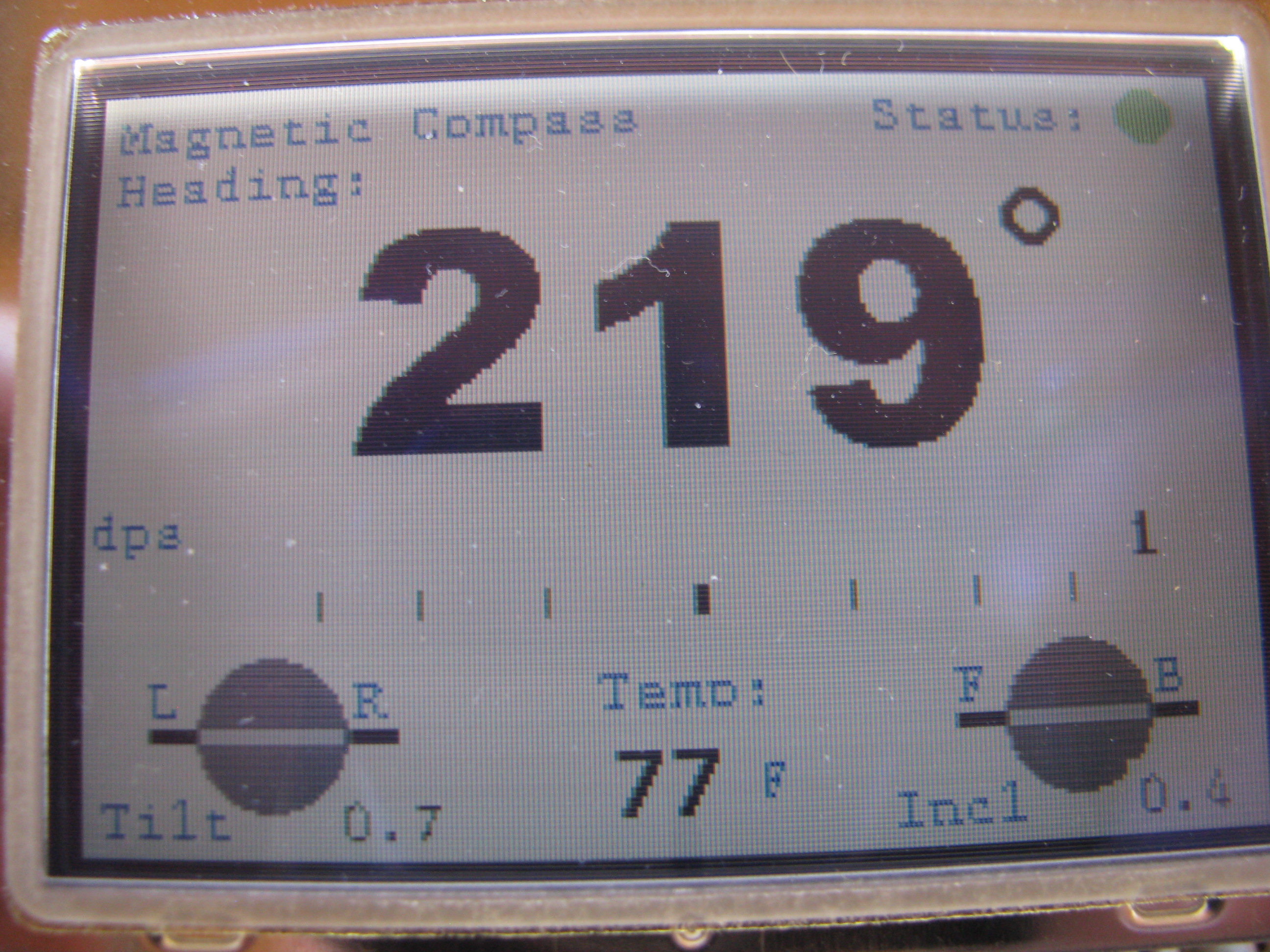
In the center there is a turn rate bar that varies in proportion to the rate of angular turn. Just like in a commercial gyro, the 3dps reading is a half scale bar. The bar deflection is proportional to the rate of turn and the displacement scale is exponential. The tilt readings are displayed since I had to compute them for the compass anyway. I calibrated the tilt against my $200 digital level and it is just as accurate.
For the uber-weenies out there, the code is attached. I make no license or warrantee that this will work for you. It works for me and that’s all I care about right now.
Air_Instrument5.ino Main program with primary execution loop
ADXL_Support.ino Support routines needed for accelerometer device
AI_Support.ino General purpose routines and conversions
AI_Types.h Data type definitions for passing vectors around
BMP085_Support.ino Routines for handling the barometric and temp sensor
Compass_Support.ino Routines for initializing, calibrating & reading the Compass Device
EZLCD_Support.ino Display device routines and drawing methods
Gyro_Support.ino Routines for driving the rate gyro device
I am extra-happy with the tilt compensation. You can now tilt the device (and ultimately the helicopter) up to about 70 degrees off level in any direction and the magnetic heading is still accurate. There is NO mechanical compass I know of that has that sort of performance envelope. Along the way I learned a ton. I plan to use that knowledge to build an airspeed indicator accurate to 5mph or less.
Beacon Strobe
LED technology has made leaps and bounds in recents years. I decided to build my own strobes based on some new 900 Lumen CRE LEDs. That’s 900 lumens each. My old-fashioned living-room flood light bulbs are each 800 lumens at 90watts, just to put that in perspective. According to the spec sheet you can get almost twice that light per device if it is not continuous duty by overdriving the current.
So six of these LEDs with a peak of 1800 lumens each gets us about 10,000 lumens. The trick is handling the current. At 4amps per device that’s 24 amps. You certainly don’t want to switch that on and off directly from the battery. The current loop in the ship’s wiring would induce its own set of problems.
So to deal with that I developed a little circuit that charges up a capacitor bank, discharges through the LEDs then charges up again. The sequence is a 25millisecond flash, pause 100 milliseconds, another 25 millisecond flash, then pause 1.5 seconds, repeat forever. The caps charge during that 1.5second delay and therefore the average current to the whole strobe unit is 0.3A at 12V and should be very easy on the rest of the ship’s systems.
Best of all, the thing weighs next to nothing. I haven’t measured, but it can’t be more than a couple of ounces.
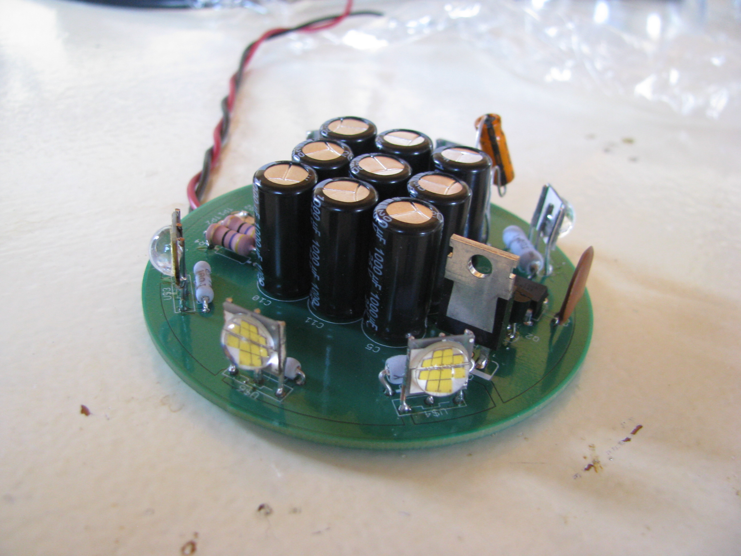
Here’s the circuit. Ignore the two capacitors dangling in the breeze. They are bulk and decoupling for the ATTiny85 microcontroller that controls the sequence. I forgot to order SMT caps from Digikey and will replace those before buttoning it up.
For those interested the schematic can be seen at Strobe_A.pdf. If you do something like this, pay attention to the ripple current rating of the capacitors. Layout is Strobe_A_top.pdf.
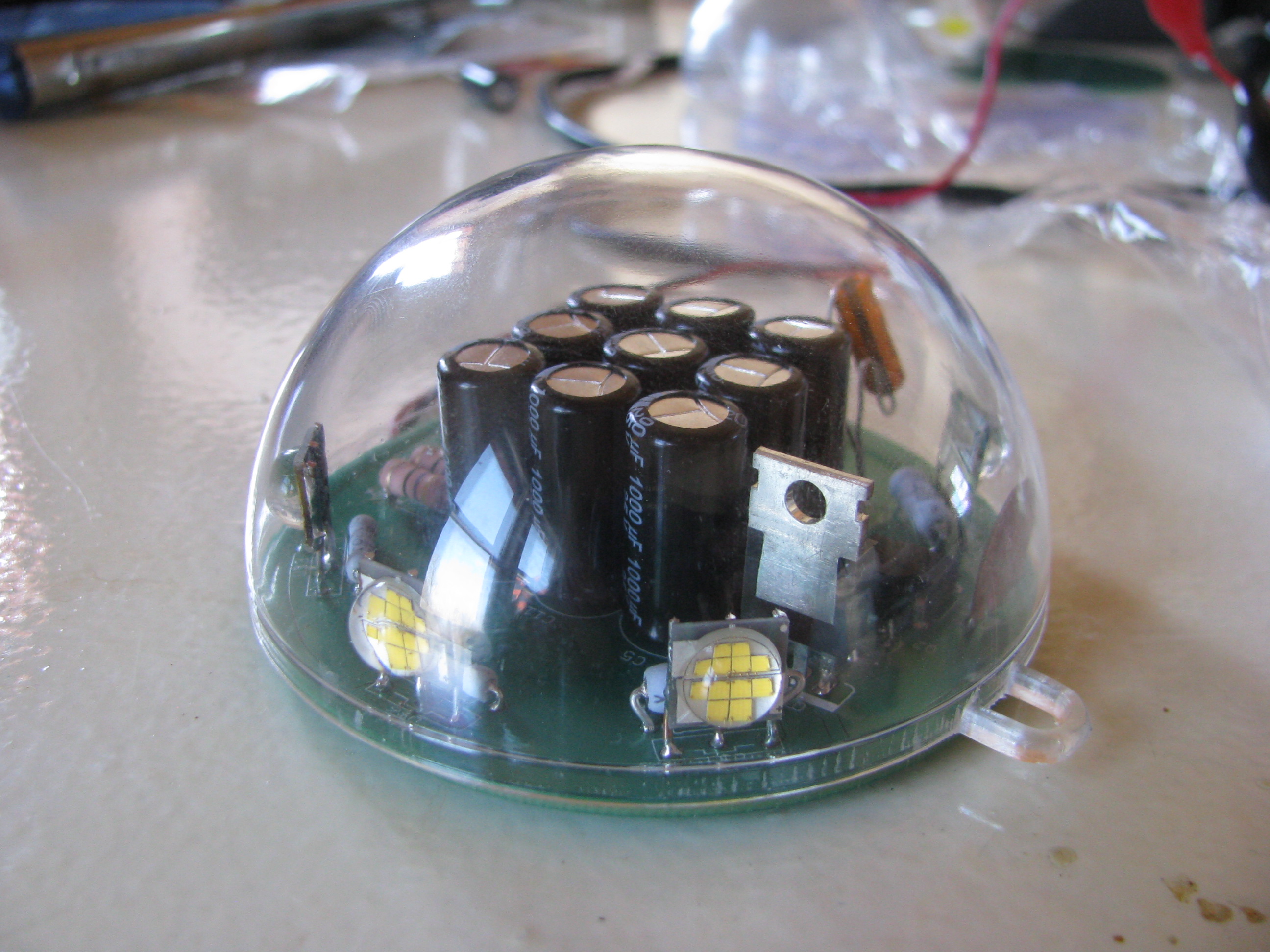
The PCB was sized to fit in a polycarbonate sphere bought at a craft store. The shell is designed to be used as a homemade christmas ornament.
I used Sunstone circuits “Value Proto” service for my PCB. This is a very cheap PCB fab process that uses unused panel space on other designs going through to keep your individual cost down. The down side is that the lead time can be long since they have to wait for a design with spare panel space - but hey, it’s very, very cheap.
If you do something like this, bear in mind that if the lights were left ON continuously (not blinking) it would heat up quickly and destroy itself. This circuit only works if the duty cycle (lights on period) is very, very low. I have left it running for days blinking along with no problems and cool to the touch, with flash pulses that are retina-melting. If you look at it directly by mistake you will see spots for an hour.
Turbine Prep
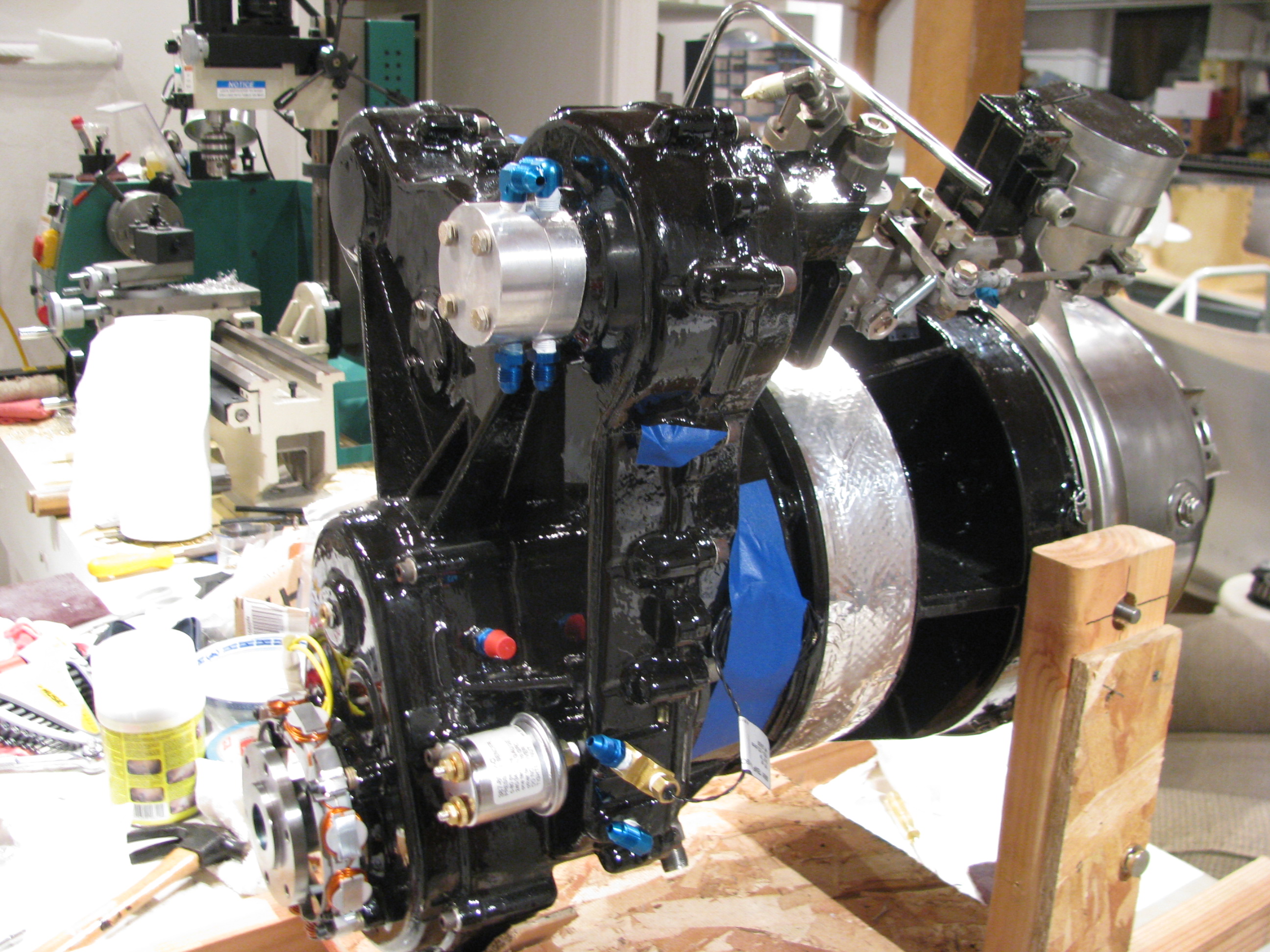
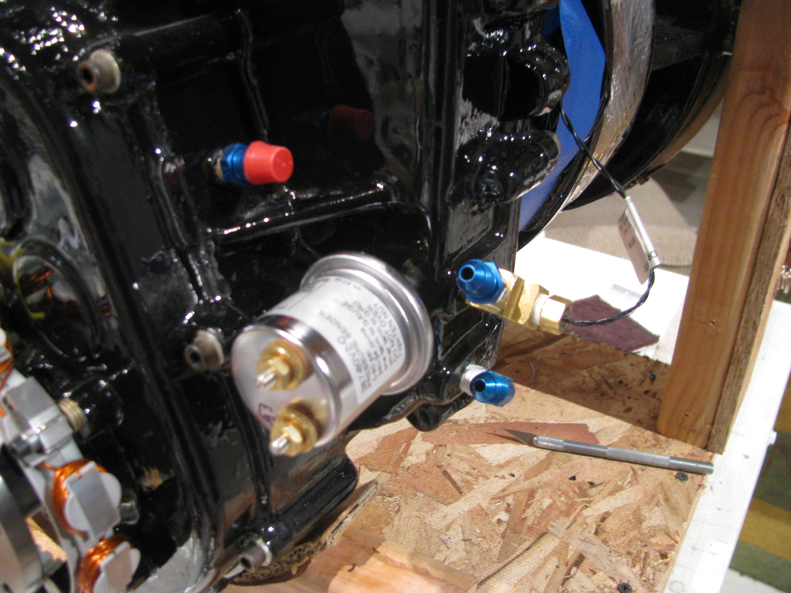
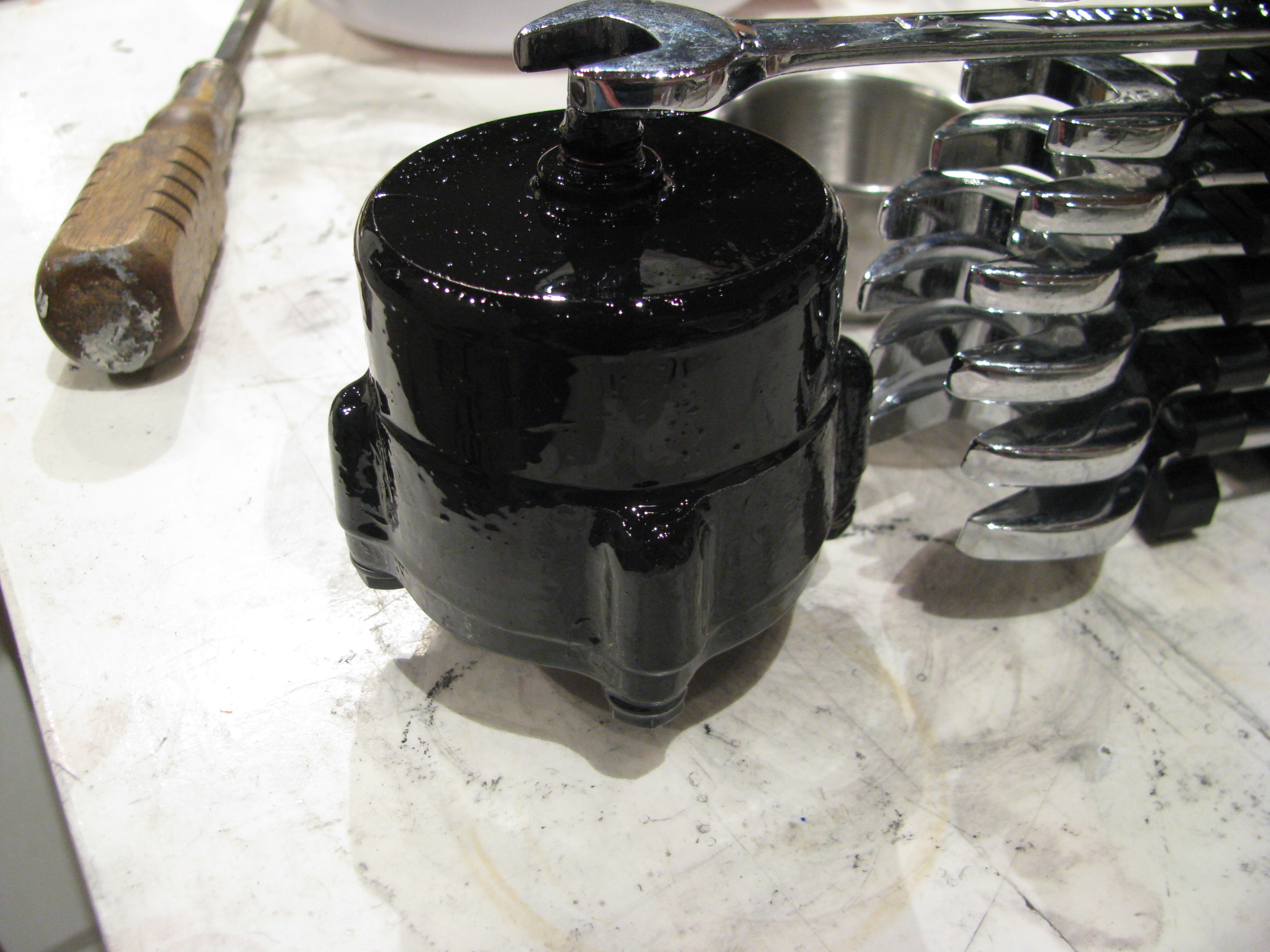
Various plumbing fittings, safety wiring, and painting of the oil filter housing.
My first oil line. I think I may have “overflared” the ends as a little ridge extruded out between the flare clamp dies which prevents the retainer ring from seating fully. This one is coming back. I practiced on a couple, but probably should have intentionally under and over flared to get a feel for what that looks like, Again, my second helicopter will be perfect.
Takes about 3 minutes to polish the line and makes a huge improvement in appearance.
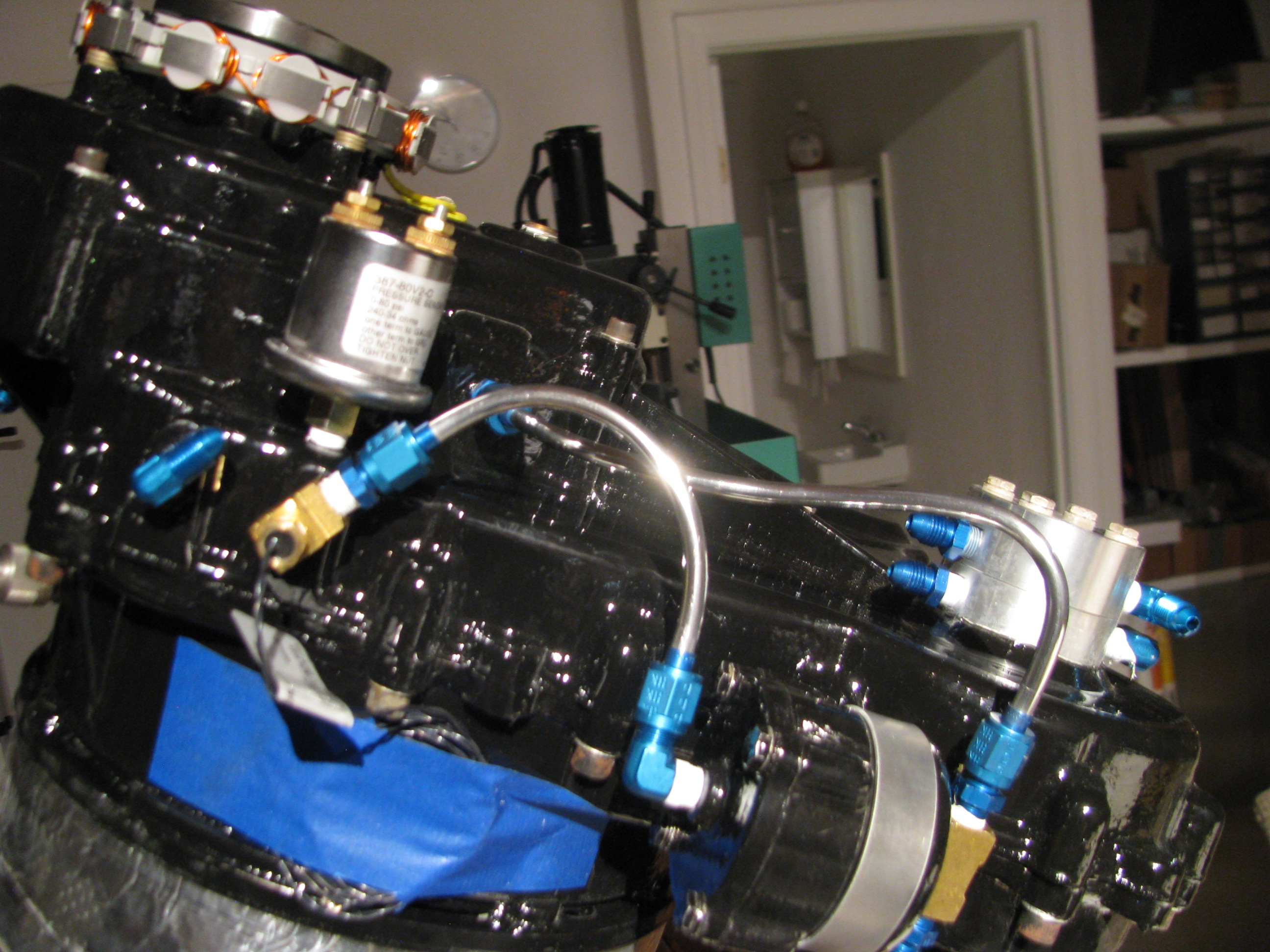
Adding more lines. Engine is tilted up for better access to lower lines.
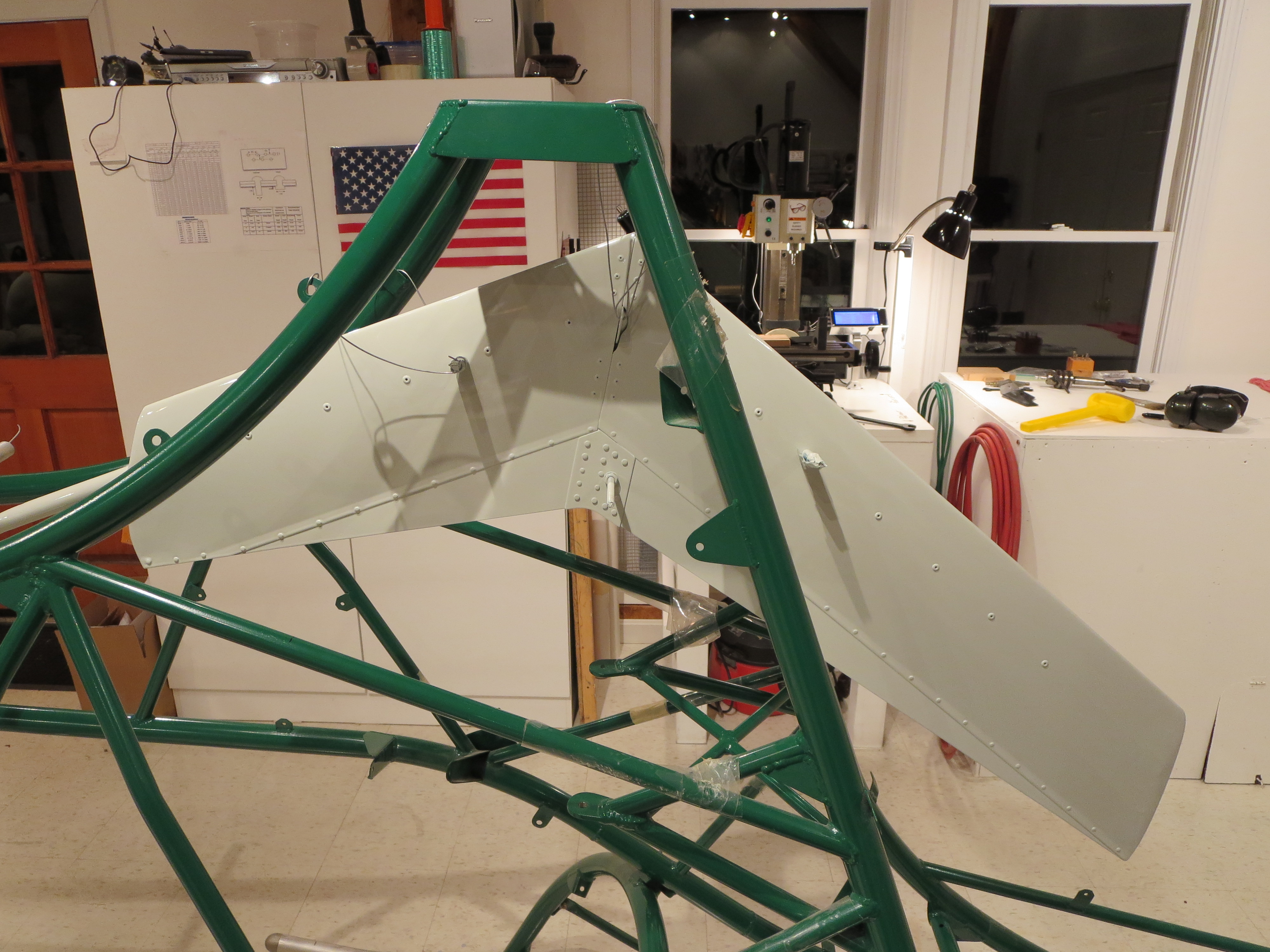
Drilling and Aligning Fins
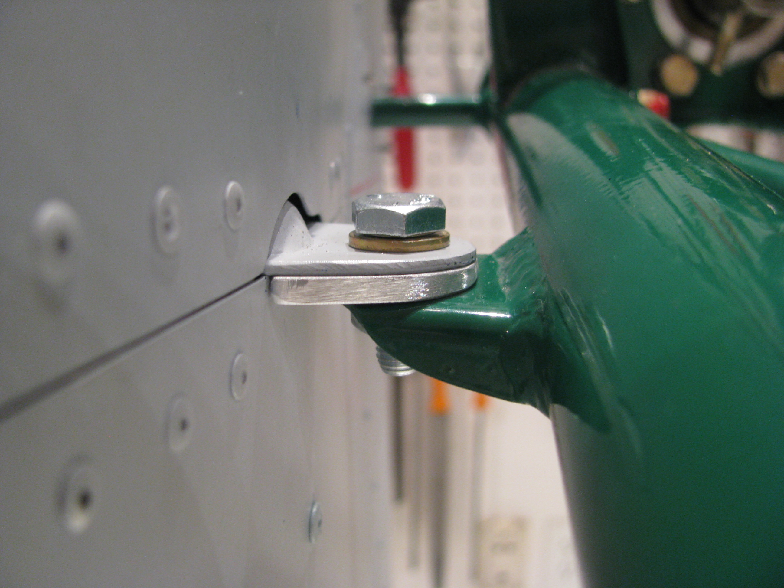
To get the horizontal fin at the correct 5° angle, and to keep the relationship of the vertical fin reasonable and the position of the rear mounting hole centered in the doublers (don’t worry, it would make sense if you were building one), I found things to work better if I placed a 0.125” spacer under the front vertical fin mount. This also allowed for the milling of a tilt to account for angular mismatch between the fin and the frame mount. Quick job on the Grizzly.
When I first started making these tubes I thought I would simply use my fabricated tubes as templates and then go have a welder make “real” tubes with a welded endplate, but I must say that I am actually pretty pleased with the results. The double MAP torch trick seems to work as Home Depot MAP torches do not seem to burn hot or concentrated enough to thoroughly melt the tube, but the flame temp (3600 degrees) is well above the annealing temp (1590 degrees) of 4130 steel.
The finished (almost) fin mounting job. I just need to redo the single lower tube, final rivet the central fin doublers, drill the horizontal fin to its mounting stub tube and fashion a bracket at the rear of the horizontal for added support to the vertical. One evening.
Of course during flight checkout all these may have to be boogered around a bit, but for now I am pleased that they are spot-on the planned dimensions and angles.
Ground Plane Mounting
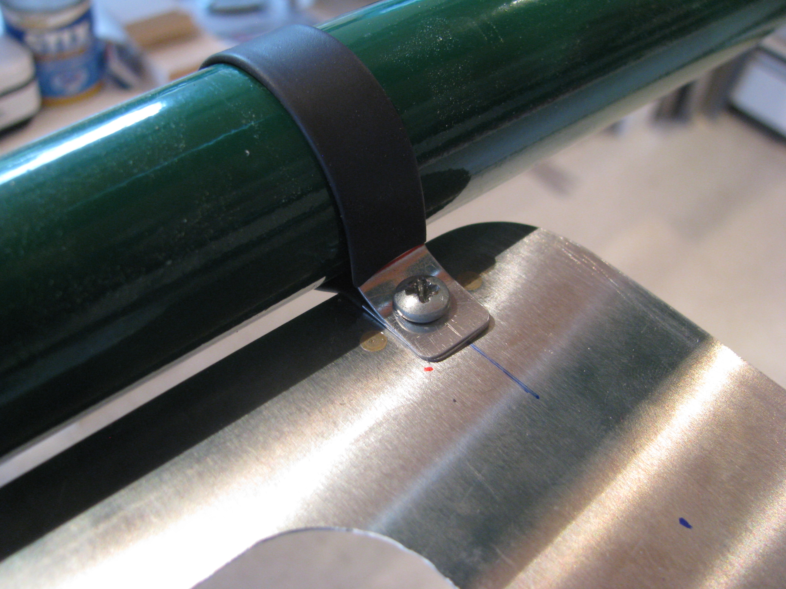
Completed the ground plane. I couldn’t see using Adel Clamps to secure it. Overkill. Instead I used little strips of 0.025 covered in shrink tube screwed through the ground plane to nutplates riveted to the bottom of the ground plane. Nice and tight, and it weighs next to nothing.
Fin Brace Tubes
I got out my torch and bent the tubes that are to support and align the tailfeathers. As with most operations that are new to me, the first one came out great, then the second two were sloppy I need a better device for squeezing and bending the heated tube that is a little more precise. I am going to do some experiments to see how strong the heated and bent tubes are as that is a questionable procedure in my mind. I am heating the tube with a pair of MAP gas torches which gets the tubes bright orange, but not cherry red. Good thing I bought an extra 3 feet of tubing from A.S.
I ended up grinding some generous curves on the outside of a couple of chunks of aluminum angle to cover the vice jaws, so that when I squeezed, the hot tubing it would have a gentle bend instead of a sharp break at the end of the angle.
Every time the tube is heated and squeezed the aluminum picks up some scale from the steel that has to be scraped off since it’s hot enough to braze the scale to the aluminum surface and stick.
Once the hot tube touches the jaws you have about 2 seconds to complete the bend before the heat is wicked away and the tube re-hardens.
Once the squeeze and the angle look good, reheat and get the whole bend bright orange to re-anneal and let it cool very slowly. I played around with more rapid cooling on test pieces and it makes a huge difference. I had one piece so hard that drill bits could not get any bite at all and just burned.
Ground Plane
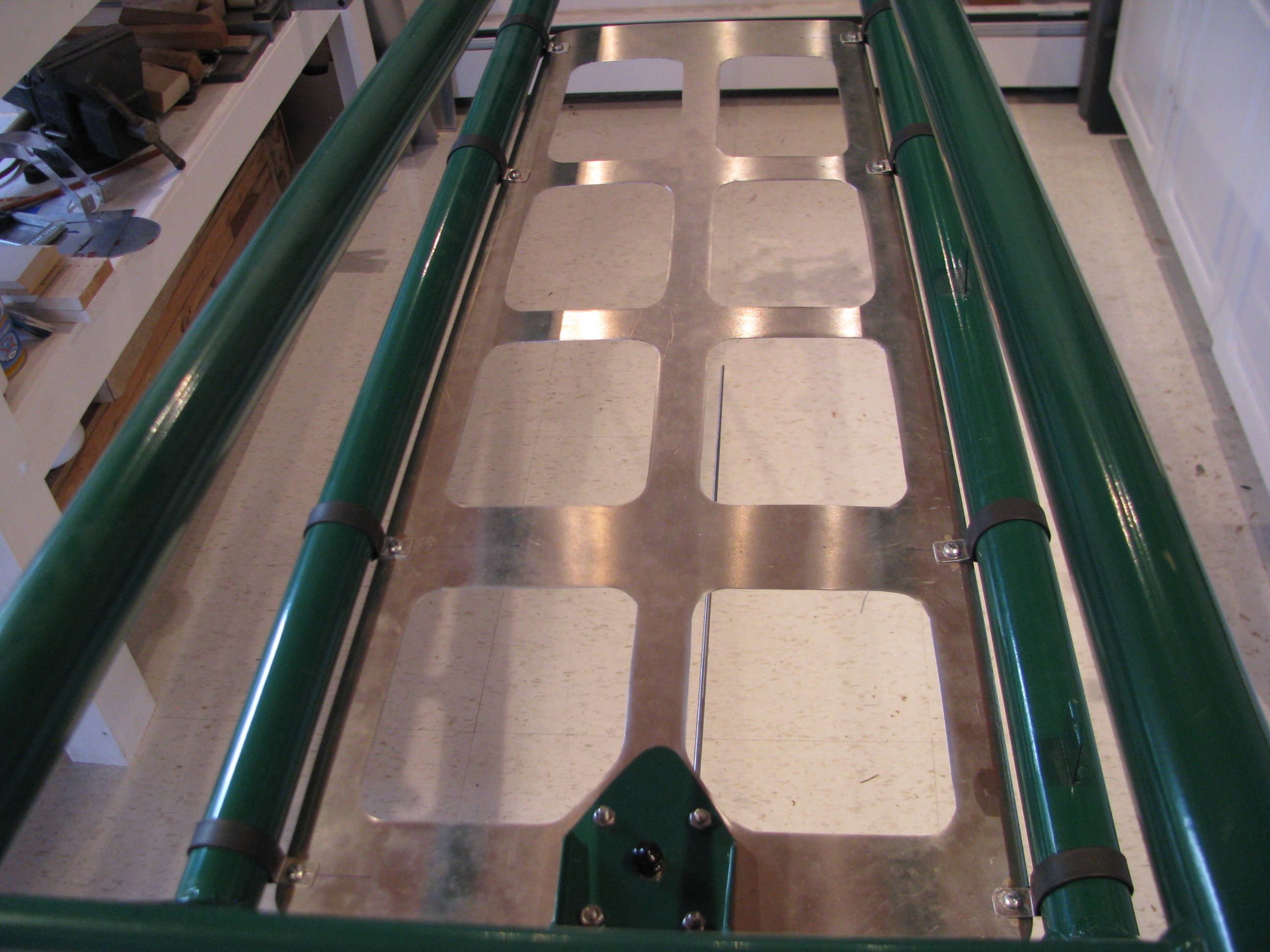
After having read Juan Rivera’s web site I decided that I would include a ground plane to improve the performance of the VHF communications antenna. The comm frequency range is 118 to 136 MHz. Therefore the 1/4 wavelength range is 21 to 25 inches. The sheet is 28 inches long. The longest diagonal opening is about 6.5 inches. No hole should be more than 1/10 wavelength (8.5 to 10 inches) so this should work well.
Cutting the sheet was a royal pain, but I didn’t want to just rivet strips together as the impedance across the joints would have adversely affected the RF performance of the ground plane. Drawing for the ground plane sheet is GroundPlane_B_072012.pdf.
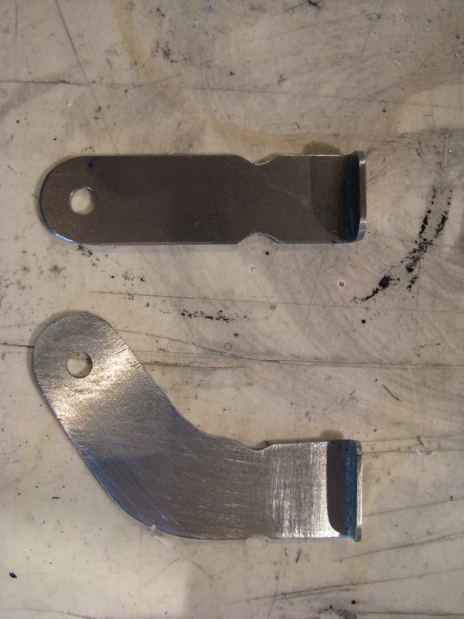
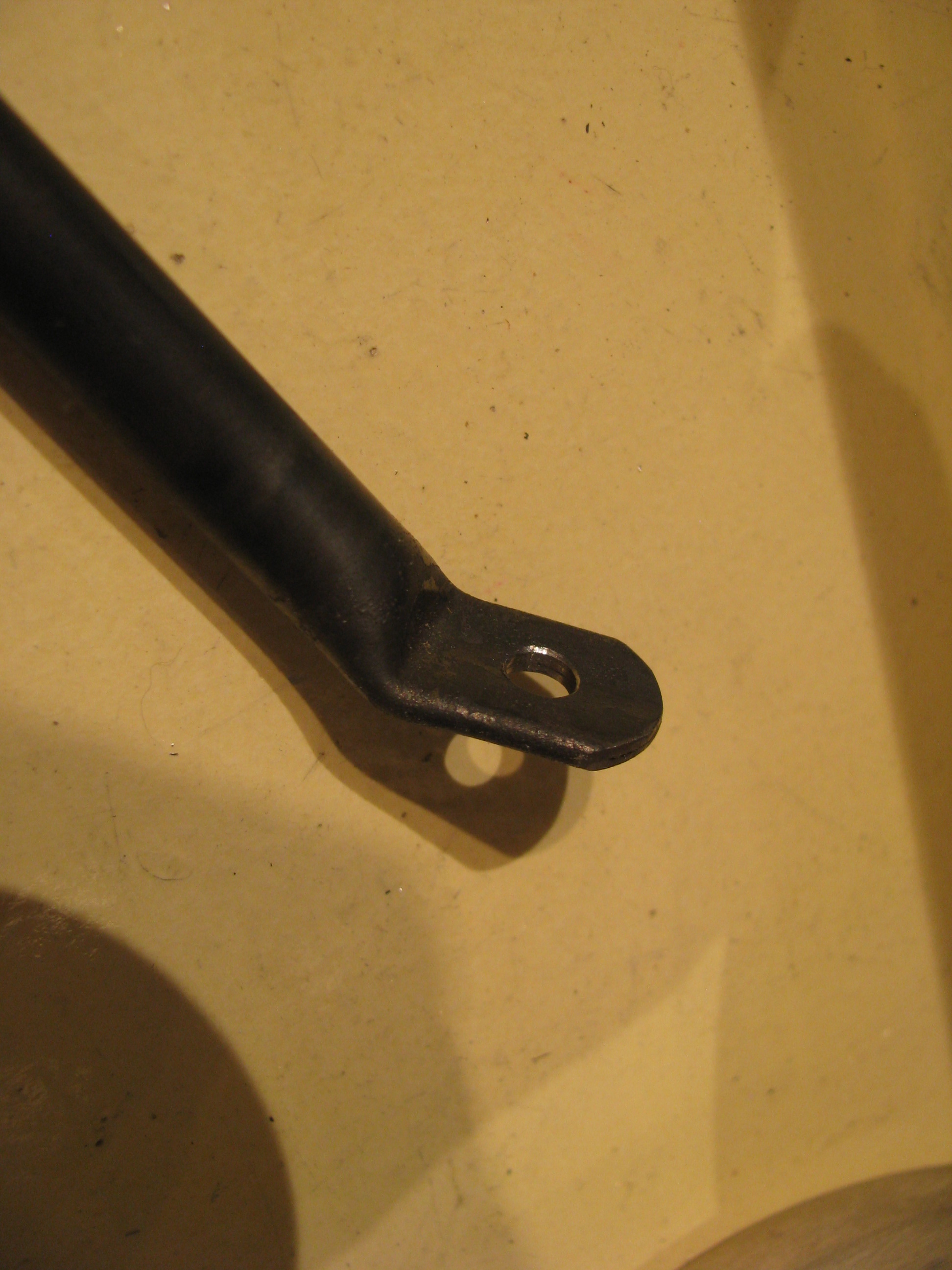
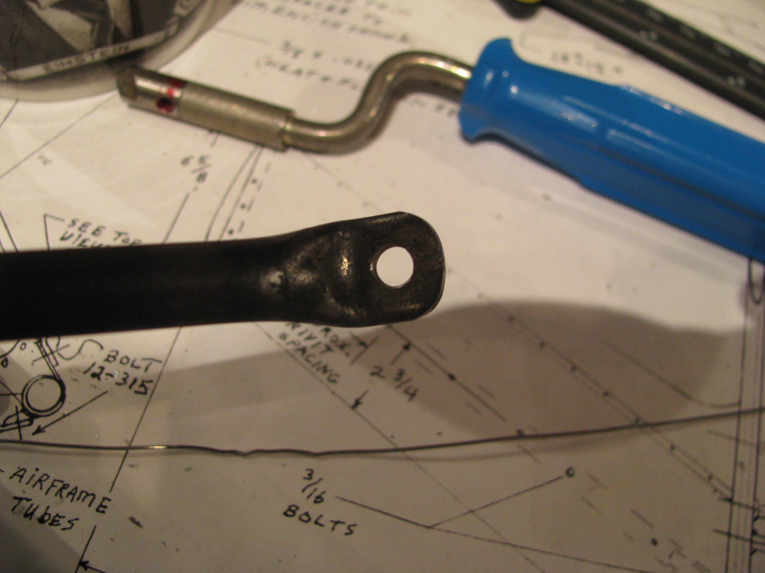
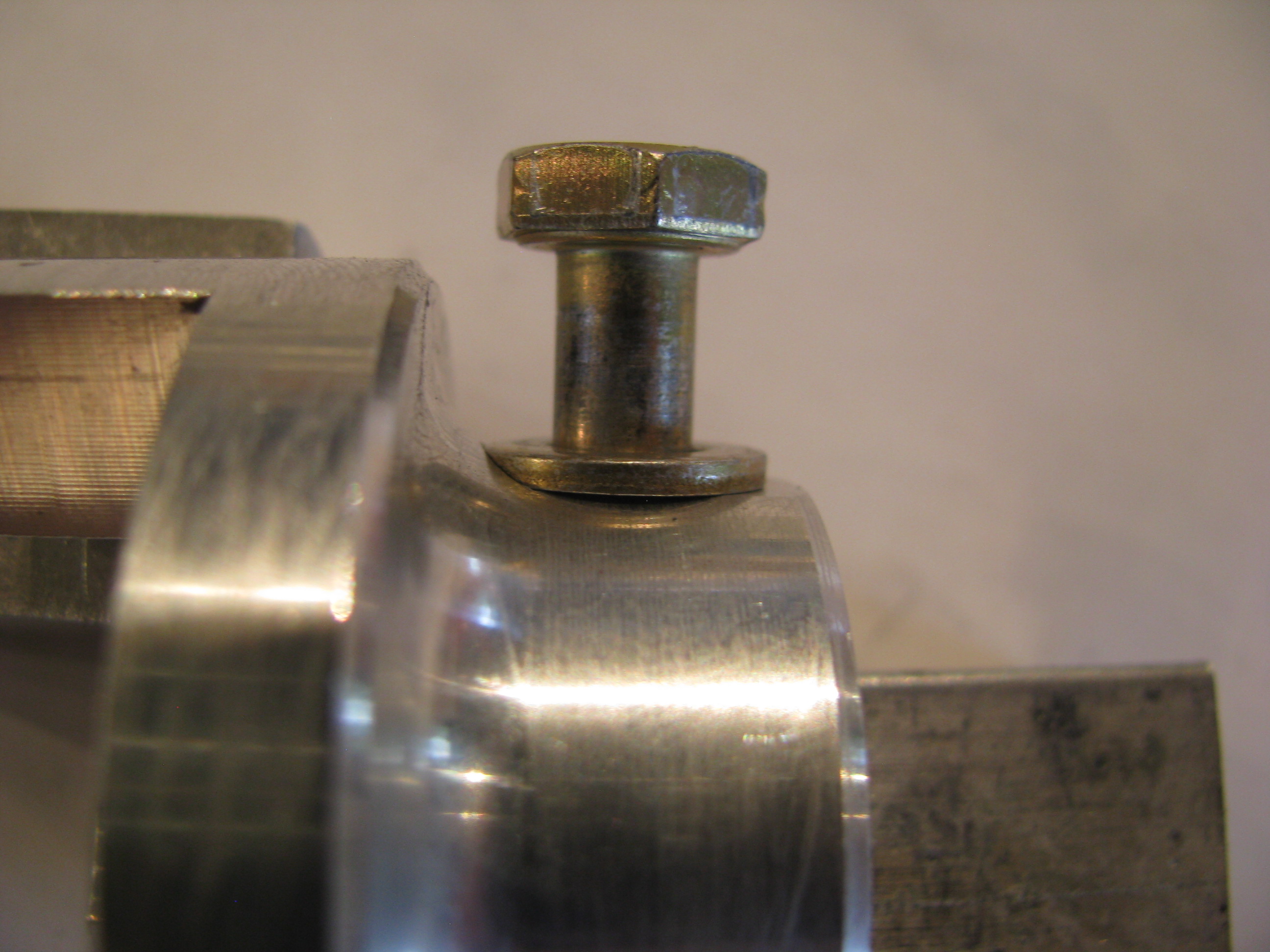
Machining Shaft Dogs
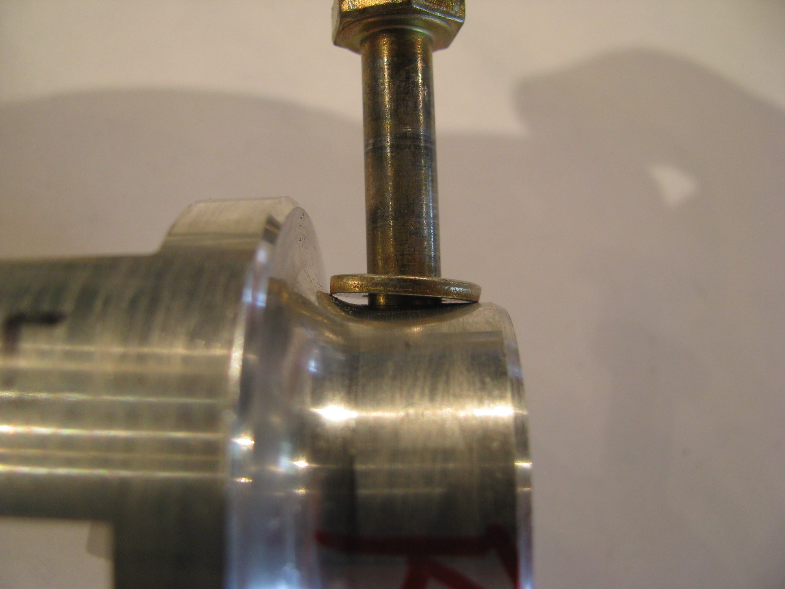
Because of the curved taper from the shaft collar to the dog face, the washer/bolt interferes with the curve.
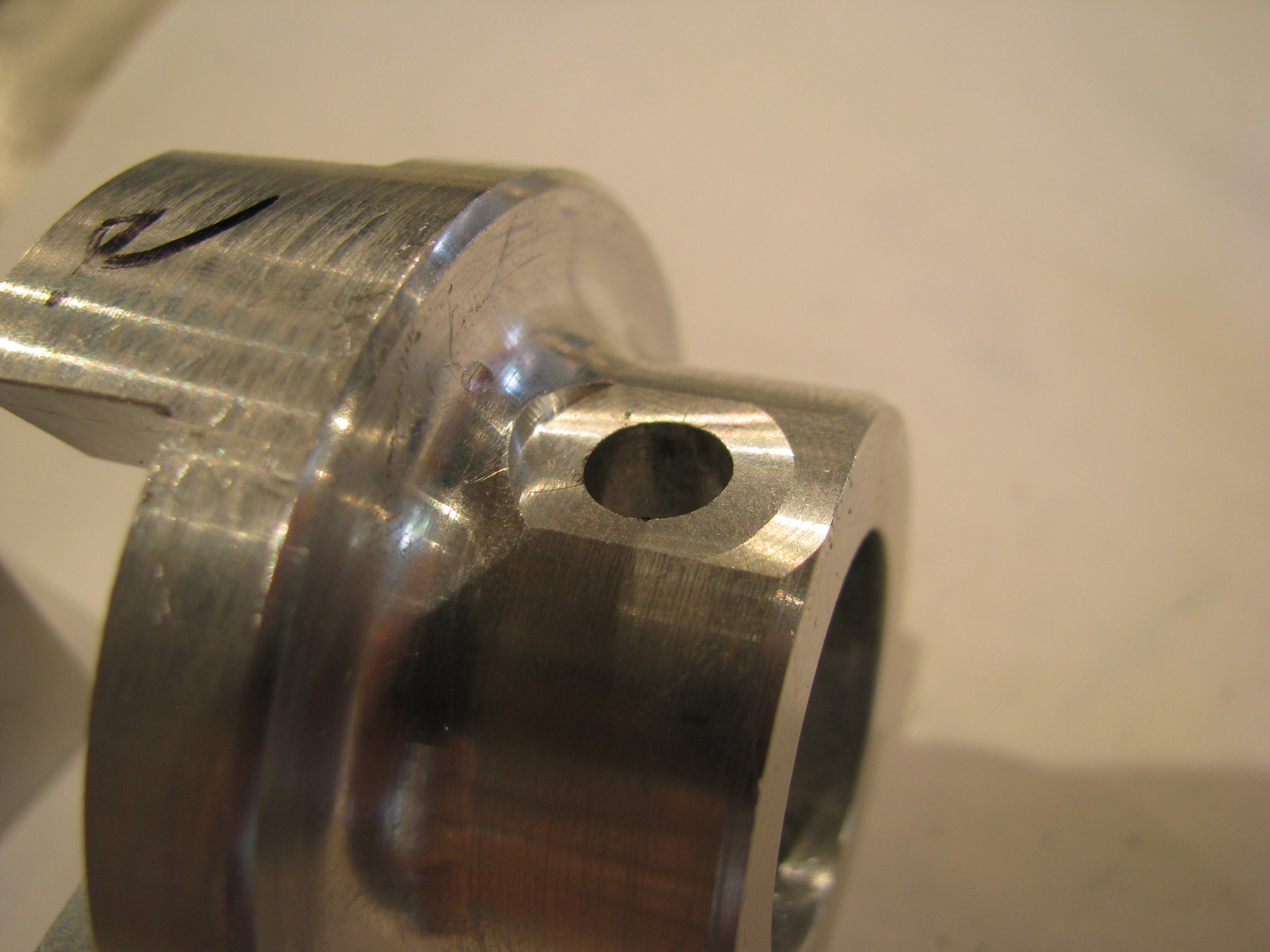
I could have filed an angle on the washers, but that seemed a little inelegant, and I DO have this wonderful mill.
Like all the machining I have done, clamping aligning and measuring is 90% of the time and the actual metal cutting takes about 12 seconds.
I was careful to not take off very much. This is a jumbo-thick part, so I am sure it is plenty strong, but I still did not want to cut full width flats as that would have eaten quite a bit more metal.
Bracket Repair
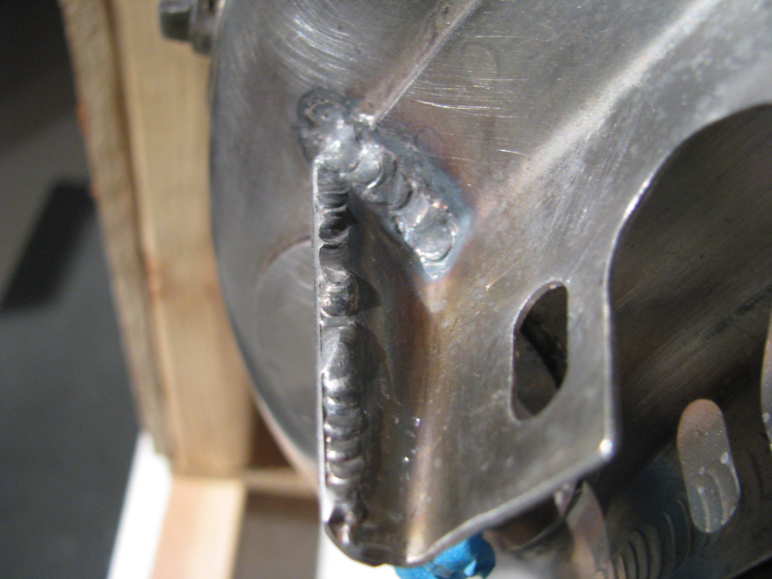
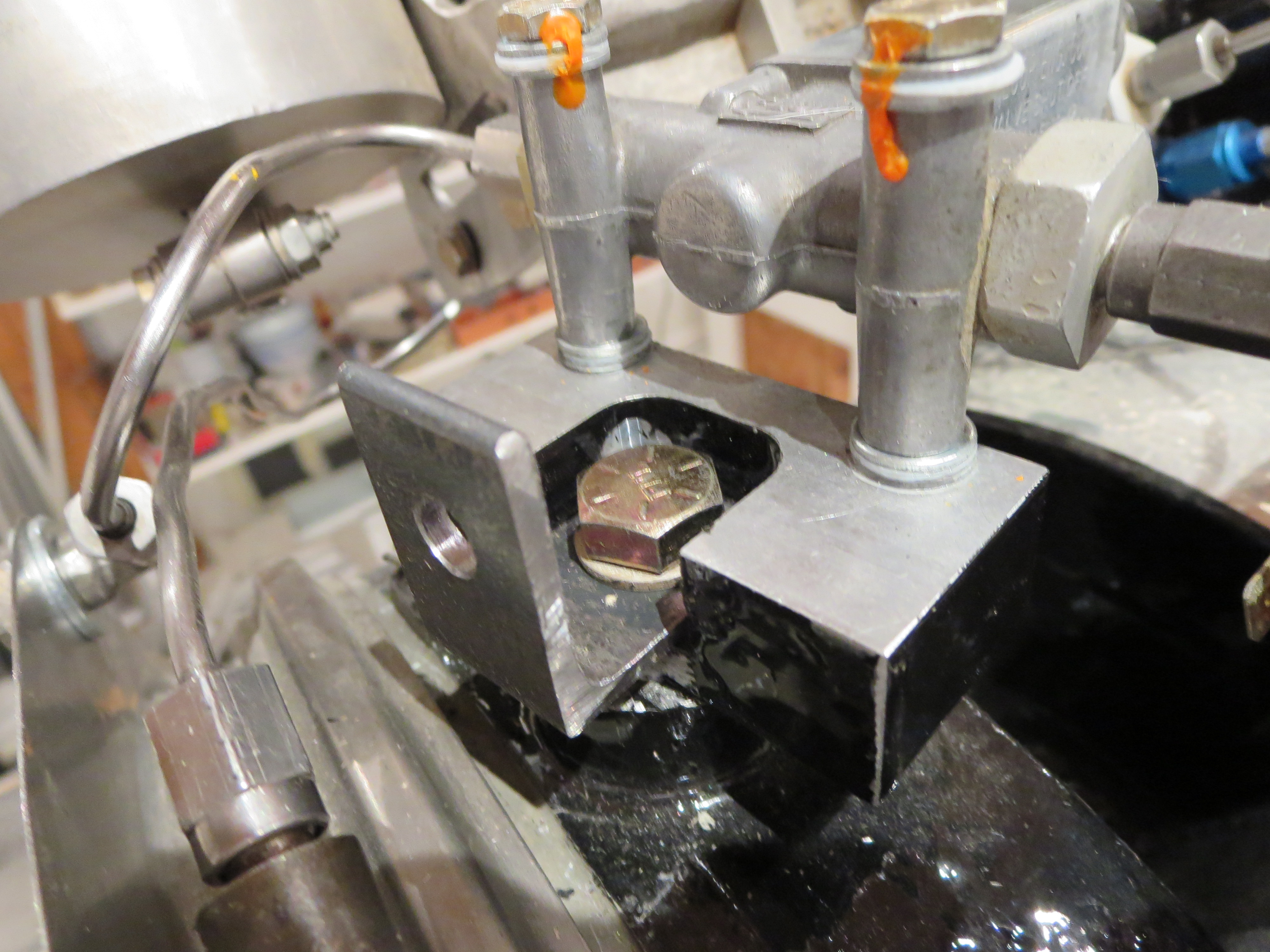
Picked up my turbine from my mechanic. The crack on the manifold bracket was welded with a little doubler to strengthen it. Much stronger and straighter now.
Initial Panel Fabrication
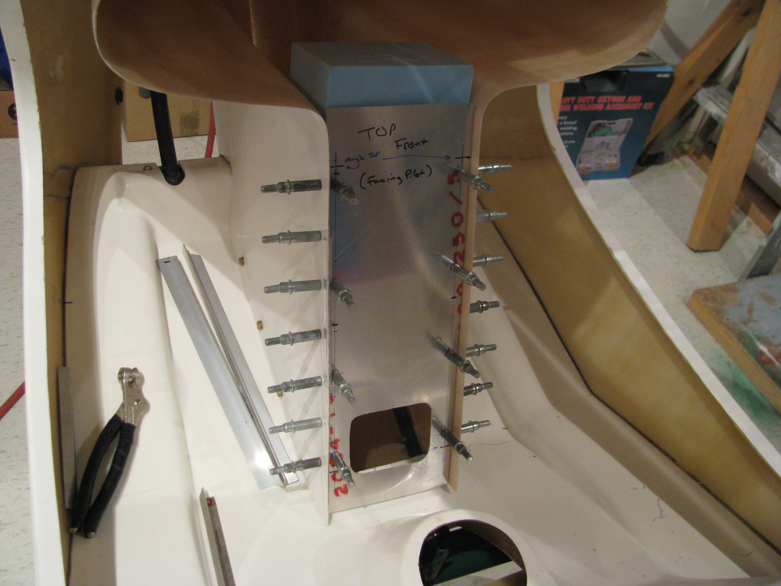
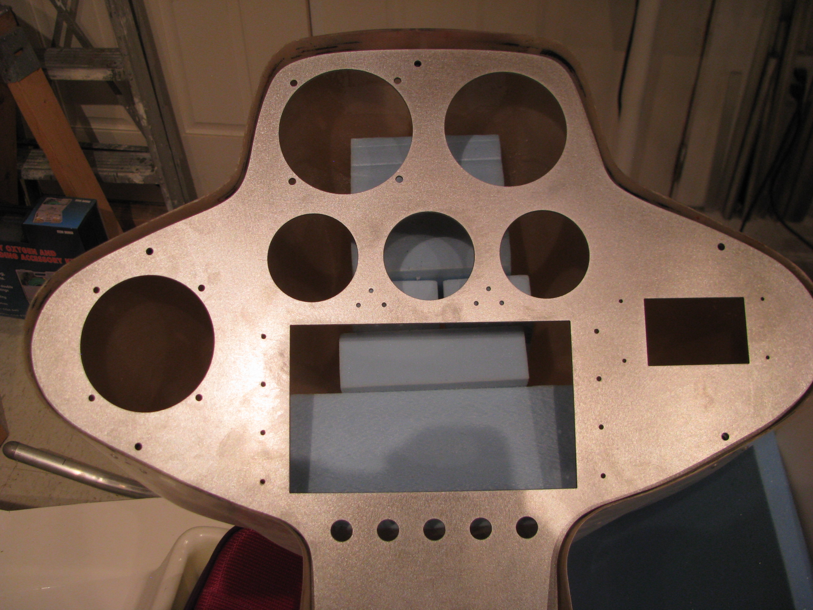
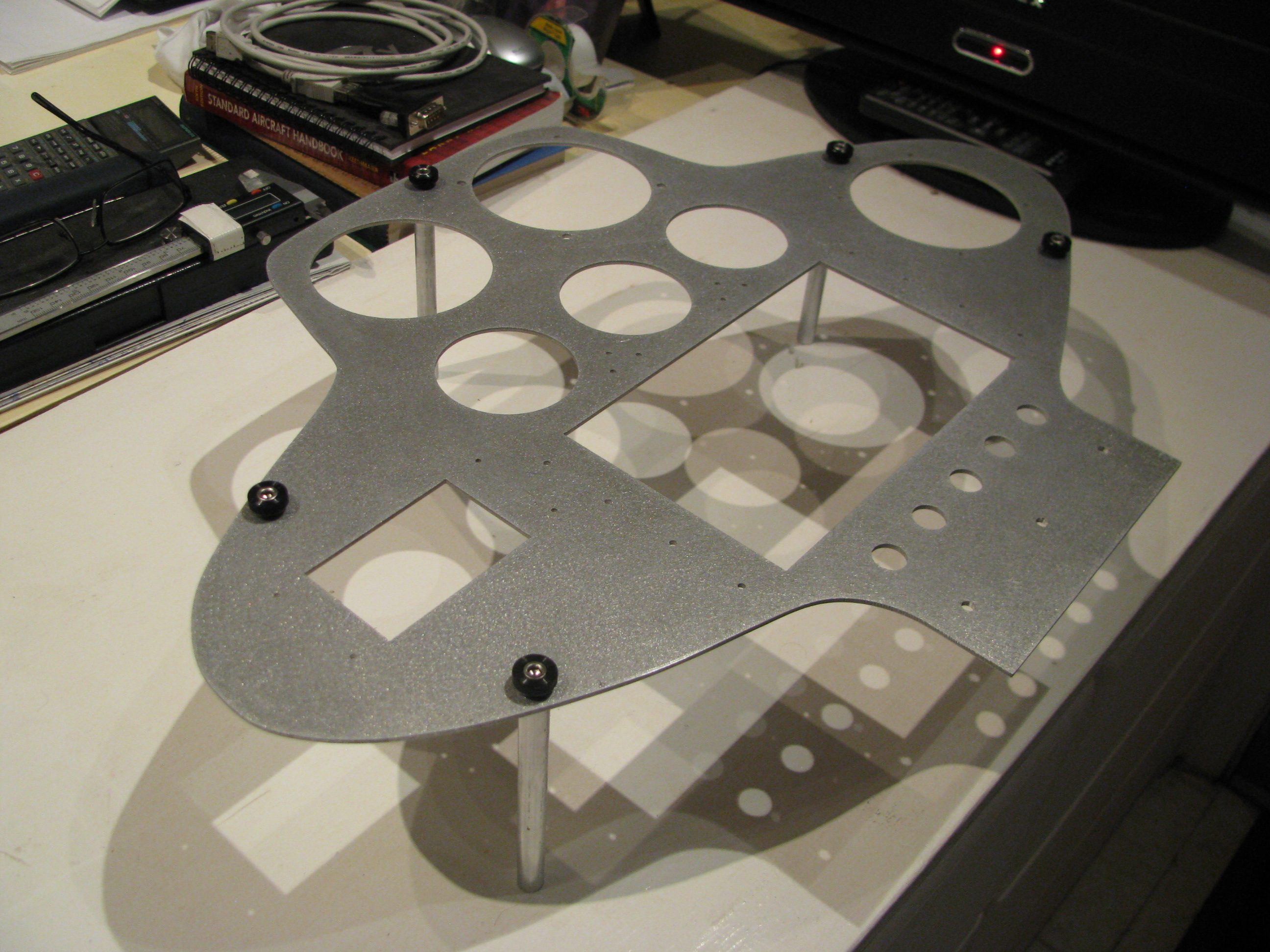
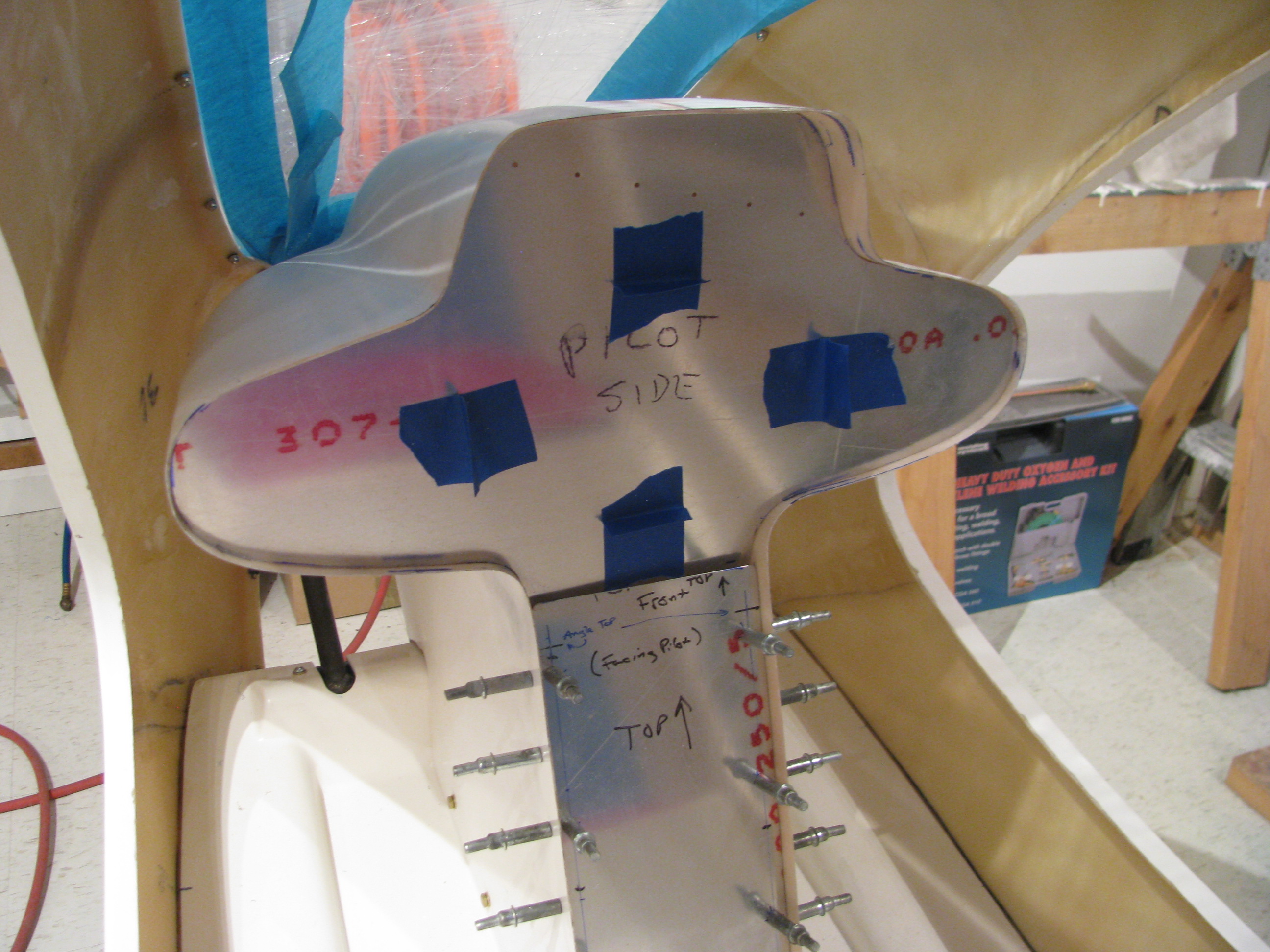
Fitting the lower instrument panel. The initial fitup is with a sacrificial aluminum sheet. Once everything is placed I will use it as a template to transfer the holes to the actual sheet to be used.
The hole is cut so I can get my hand in there and place a bracket on the pan to affix the panel on the lower edge, which should definitely strengthen things up. Screwing it in will be a pain since the cyclic riser is in the way, but not too bad with a 90 degree phillips.
Initial cutout of the upper. This again is a sacrificial piece of aluminum. I wanted to see where I stand before messing around with the shape.
Obviously the upper instrument pod is flatter and narrower than the specified dimensions by a lot.
The drawing sheet shows an 18 3/8” width at the widest point. I am seeing almost an inch wider and and inch and a half “shorter” from the bottom to the top. I am going to have to shim the side lobes to get more vertical space and hopefully narrow it up some.
I’ll use some blue foam blocks to push the upper section up, but probably won’t get to the specified dimensions without really distorting the pod from it’s relaxed state, which I don’t want to do. The primary requirement is that the side lobes be large enough for a 3-1/8” instrument. Once that is close enough for me I will glass in the foam spacer blocks.
Engine Stand
Not much happening here. I built a dolly to carry the turbine out so I can take it to be welded on the fuel manifold bracket.
Received Fixed Bearing
After more than a month I received my rebuilt tail rotor slider bearing from Eagle. Smooth. I can now finish up the tail rotor assembly.
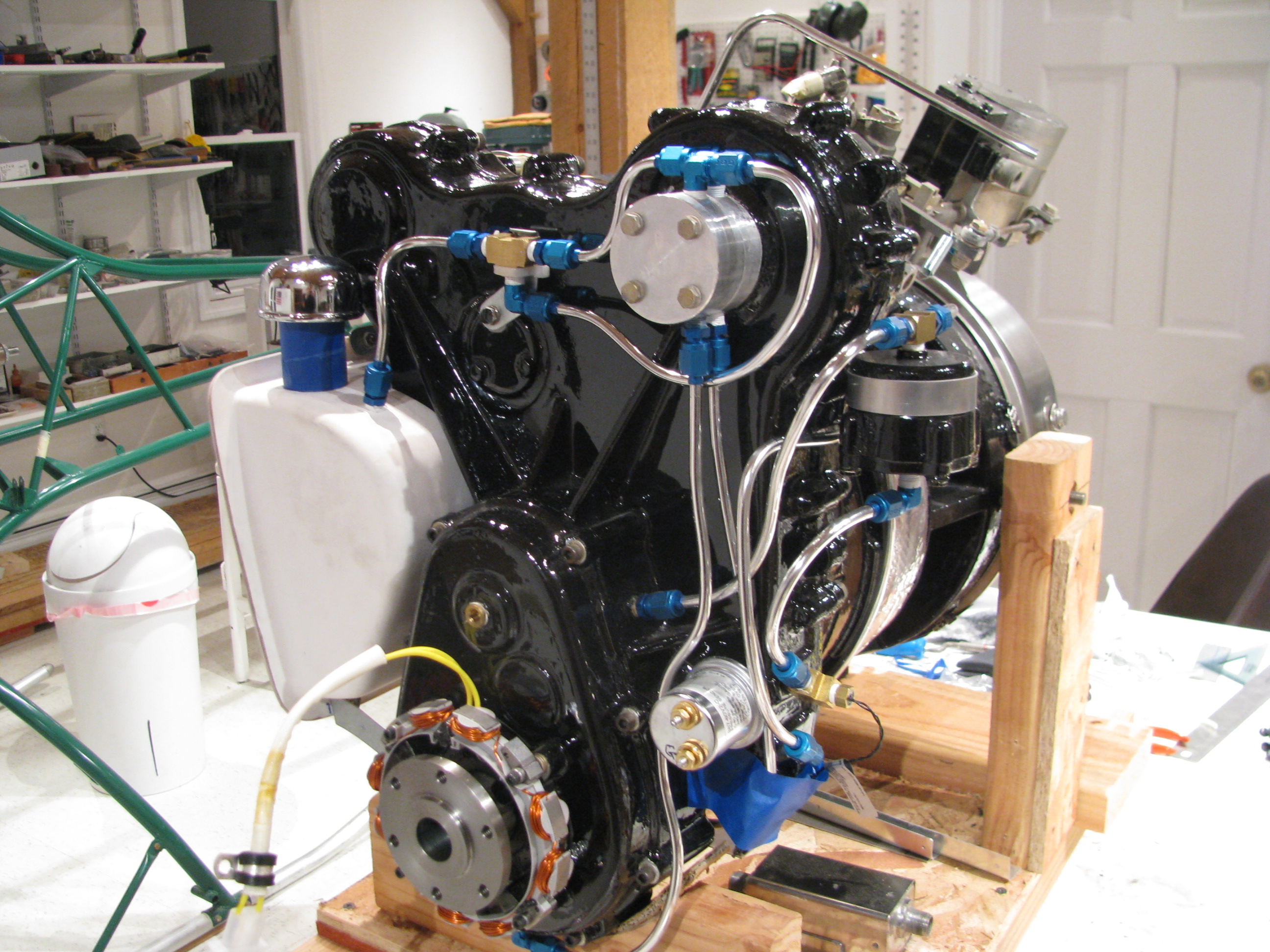
POR15 Engine Painting
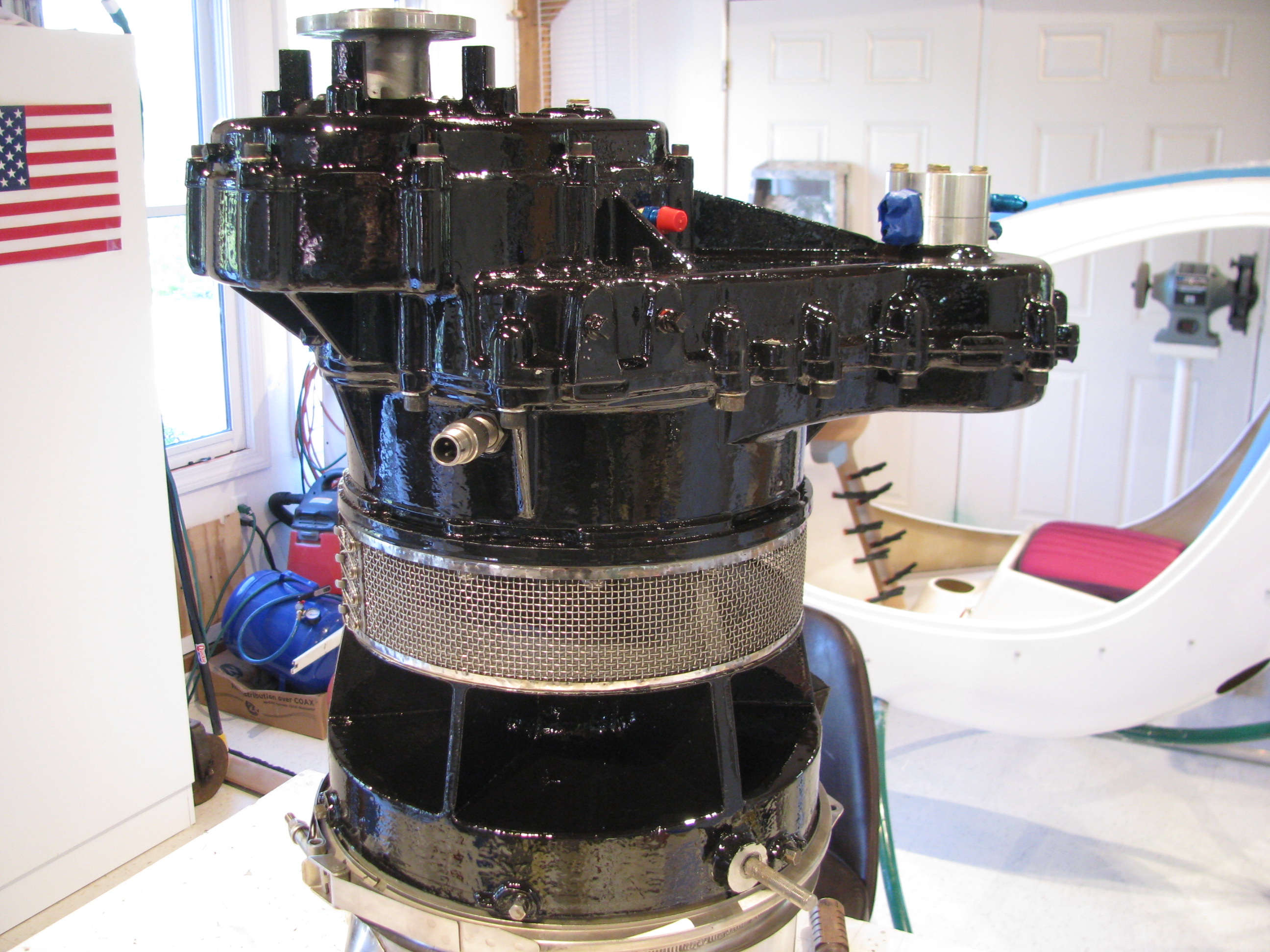
The engine has been painted with POR-15 gloss black. This stuff is really shiny and flows out oh so slowly.
The most time-consuming part was masking all the heads of the allen head bolts. That took forever and then was painful to remove as the POR really grabbed the tape.
I had to touch it up with an artists brush after removing the masking tape. but it’s finally done.
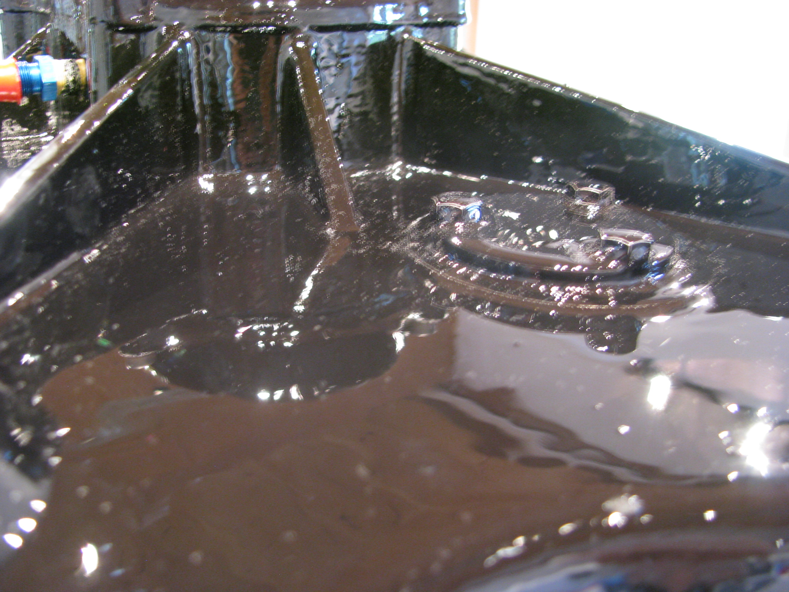
The POR-15 flows out very slowly. I can’t believe this is a brushed-on finish.
Now this is a rough casting, so I was not expecting a show quality finish, and it isn’t, but overall I a pleased with the outcome. The paint flowed out evenly and the brush marks disappeared.
It appears to be a thick, tough finish.
Cracked Manifold Bracket
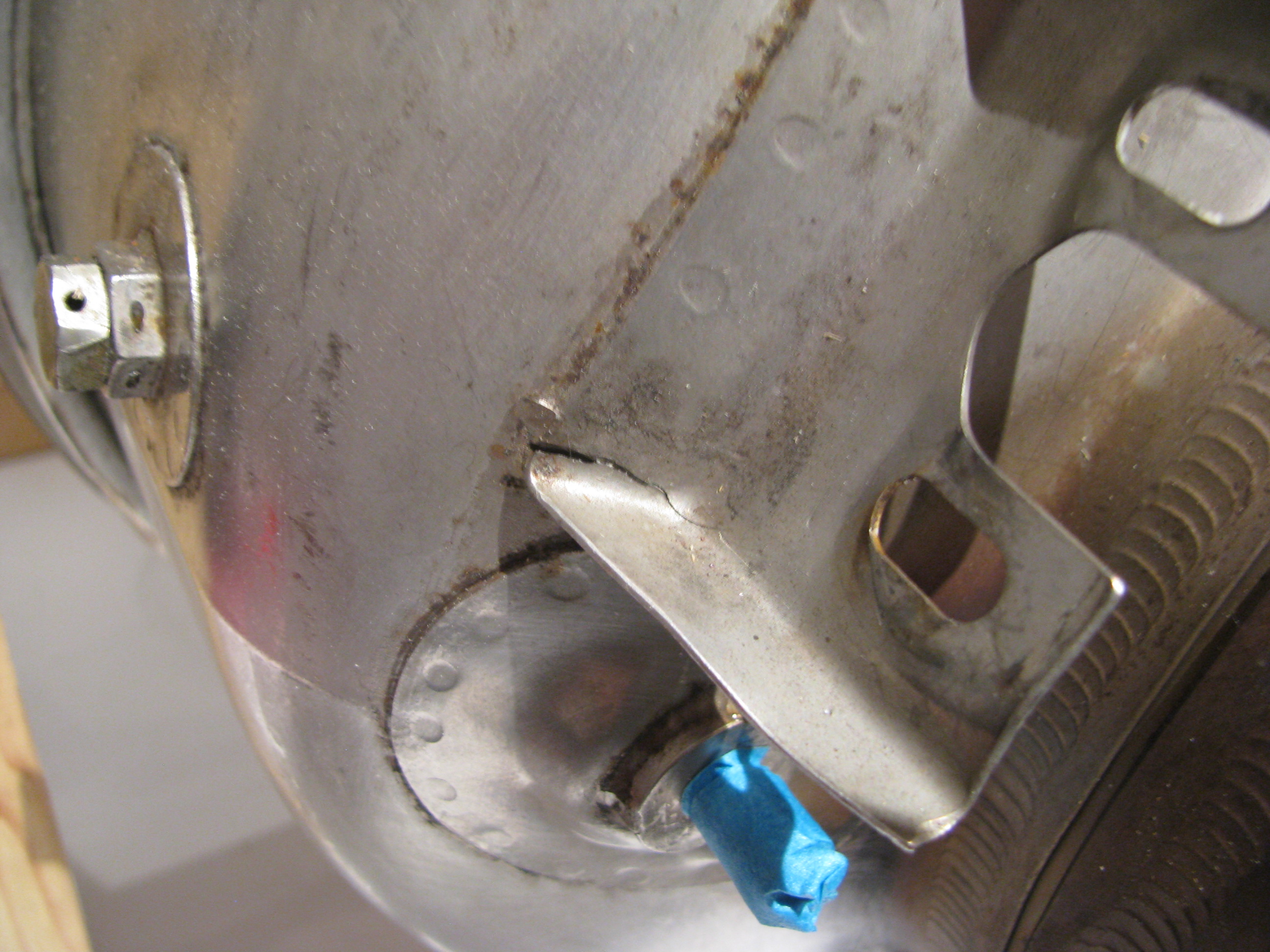
One flaw I noticed was that the bracket on which the fuel distribution manifold is mounted is cracked. You can just see the crack in the bent angle of the bracket. I will have to have this rewelded before the engine goes in. It really wasn’t evident until the manifold was removed, so I can’t really get down on Eagle for this. I will truck the engine over to my airplane mechanics to be repaired before starting re-assembly.
Paint Planning
Now maybe because I’ve been staring at it in the raw gelcoat for so long, the white has kind of grown on me. Green frame, white fins and cabin with a flat black interior (low reflections). That’s the working direction. Basic, not gaudy. Works with the green and won’t offend anyone, nor will it impress with any great inspiration or creativity either. I should be able to pull this off myself since there are no swoopy transitions and multi-color blends. I may add some trim colors, but only later and maybe with vinyl graphics.
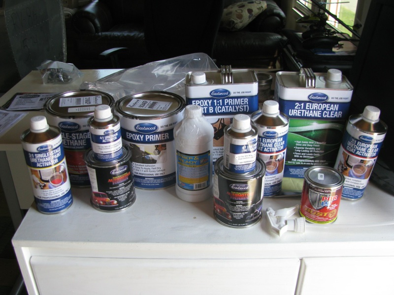
Does the table at the top look impressive? It should. That’s $450 worth of painting chemicals. I am quite sure I bought way too much flat black and not enough white, but we’ll see. Eastwood had the stuff to me within 4 days and I didn’t pay for any expedites (every can was dented, but not breached).
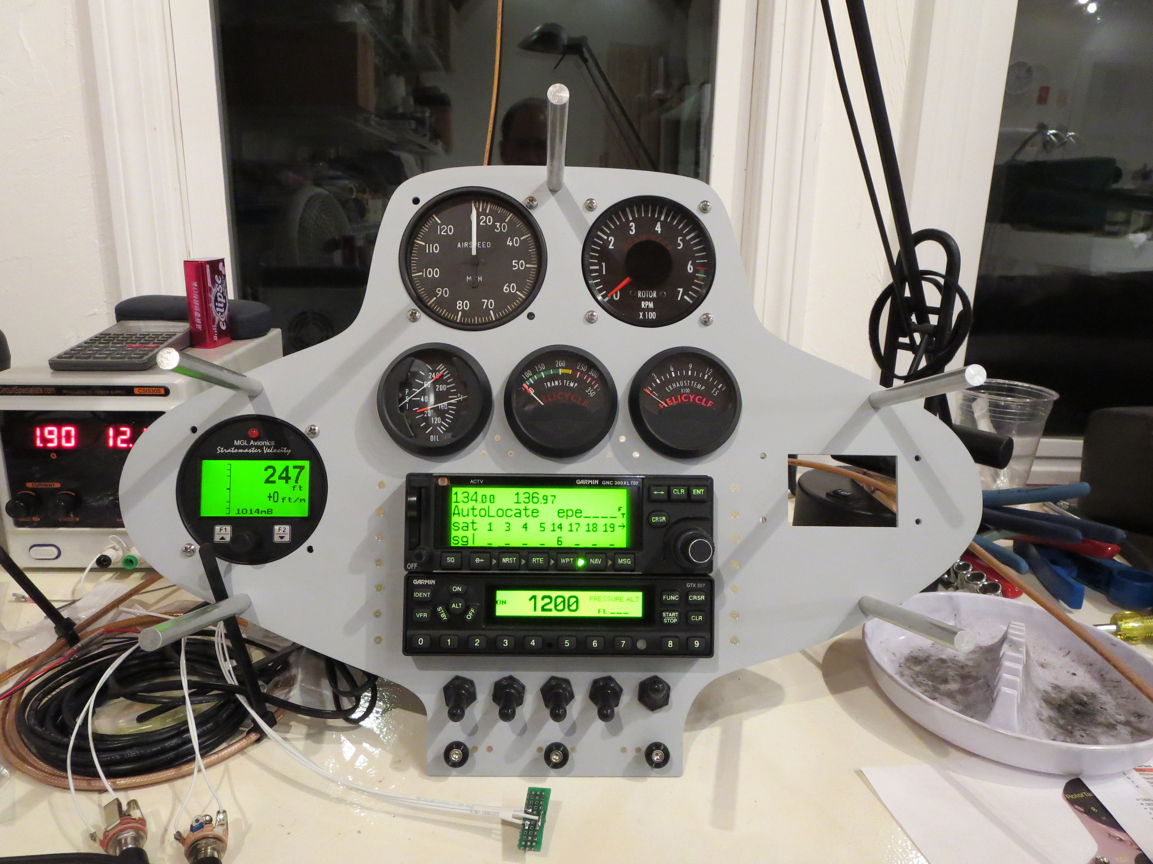
Instrument Panel Planning & Fitting
Instruments planned for the upper pod:
TOP ROW: Airspeed Indicator, Rotor RPM
MIDDLE ROW: Altitude, temp gauges, Flow Level/Flow, Vertical Speed
BOTTOM: GPS/COMM , Transponder, Compass
Lower Section: Switches, Engine RPM, Breakers
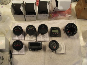
All but one of these are provided with the kit; Voltage, Transmission Temp, Hour Meter, Flow Flow (I supplied), Tachometer, Turbine Exhaust Temp, Engine Tach, and Oil Temp and Pressure.
Leftover from my RV8A project is a Garmin GNC300XL GPS/COMM and a GTX327 transponder.
Left to purchase is an AS indicator, Altimeter, and VSI.
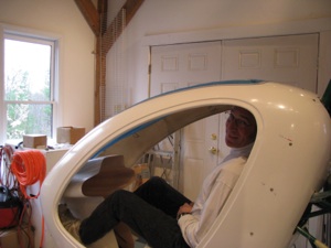
Checking the instrument pod positioning. And... making helicopter noises. One of those FAA “builder” pictures.

I ordered a Falcon 0-120MPH airspeed indicator and decided to try something a little different for the altitude. I ordered an MGL combined digital Altimeter and VSI.
Unlike fixed wing flying, I find myself really only relying on the altimeter around airports and airspace in a helicopter. You’re flying is so low and slow that visual reference for altitude is pretty accurate. The VSI bar looks quite attention-getting, which is the important thing. We’ll see how this works.
Stripped Turbine
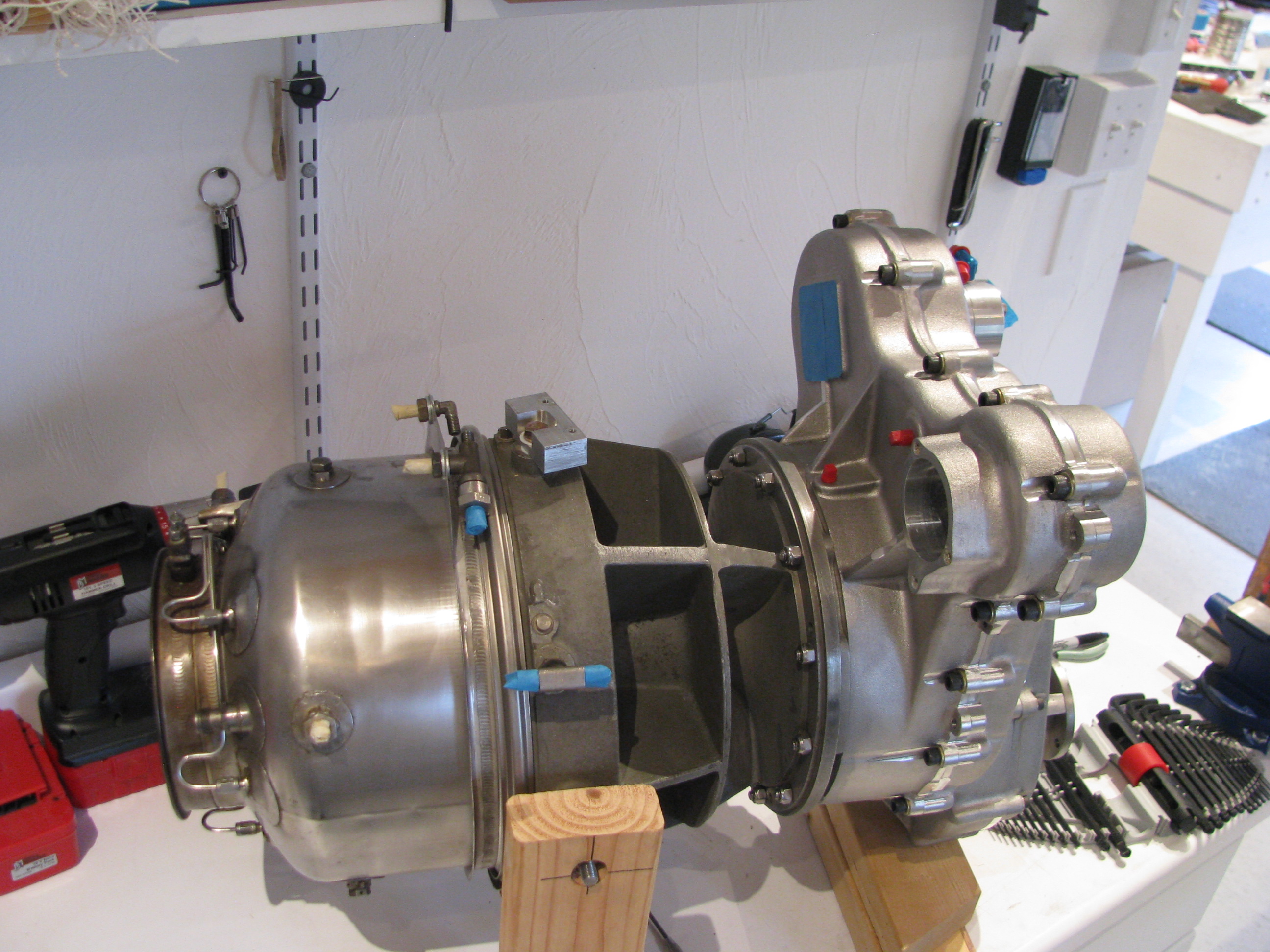
Nearly fully denuded. I am going to remove the fuel injection manifold as there is quite a bit of corrosion in the area where the tailpipe clamp goes. Mainly cosmetic, but it looks pretty bad. It will also allow for more shining up of the burner can. 10 minutes on that top section and it looks OK.
I’ve ordered some black POR-15 to paint everything but the burner can. I would have used clear, but that center section is so discolored that there is no way I could get it looking good.
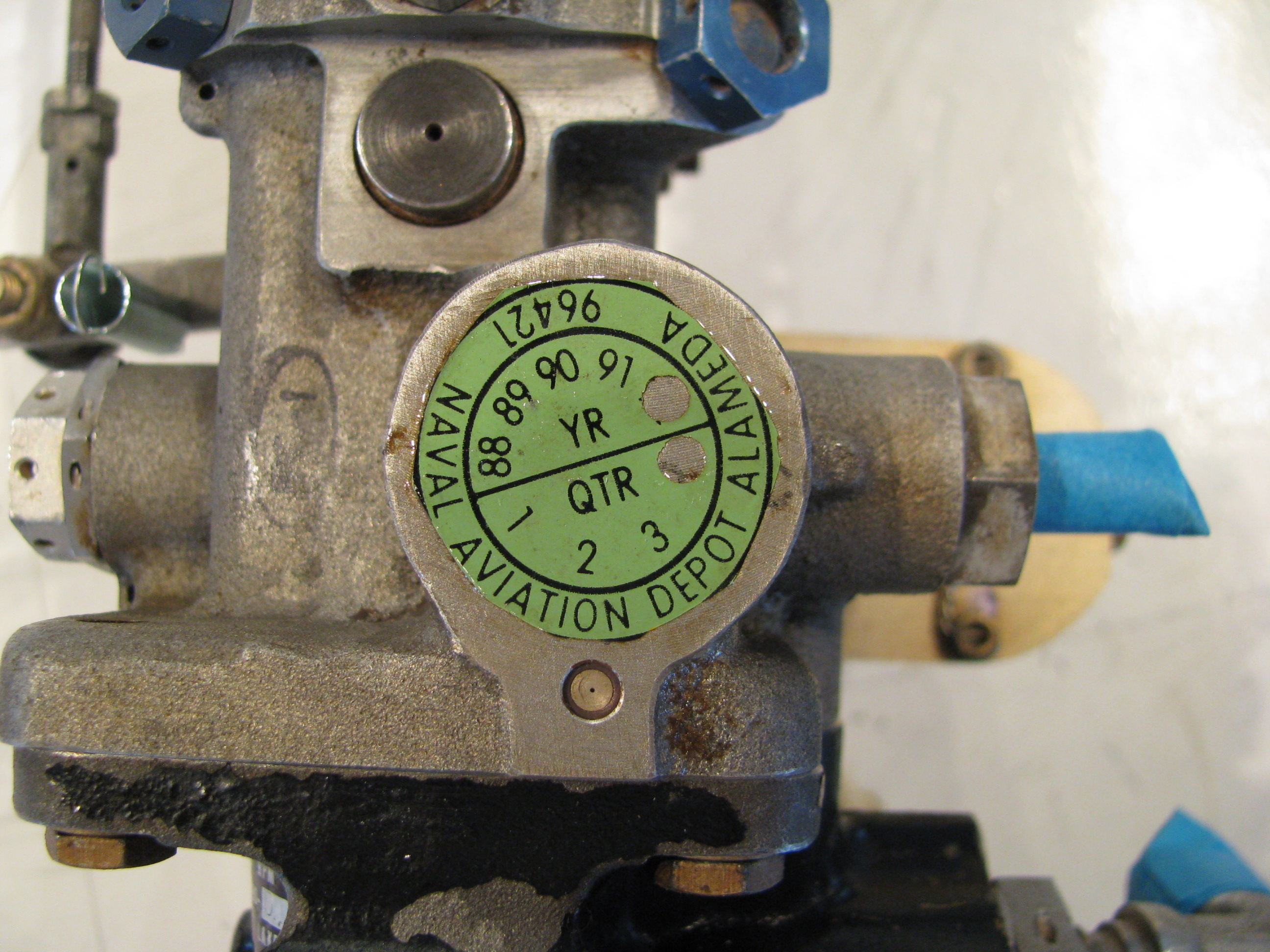
A clue as to the past life of this turbine.
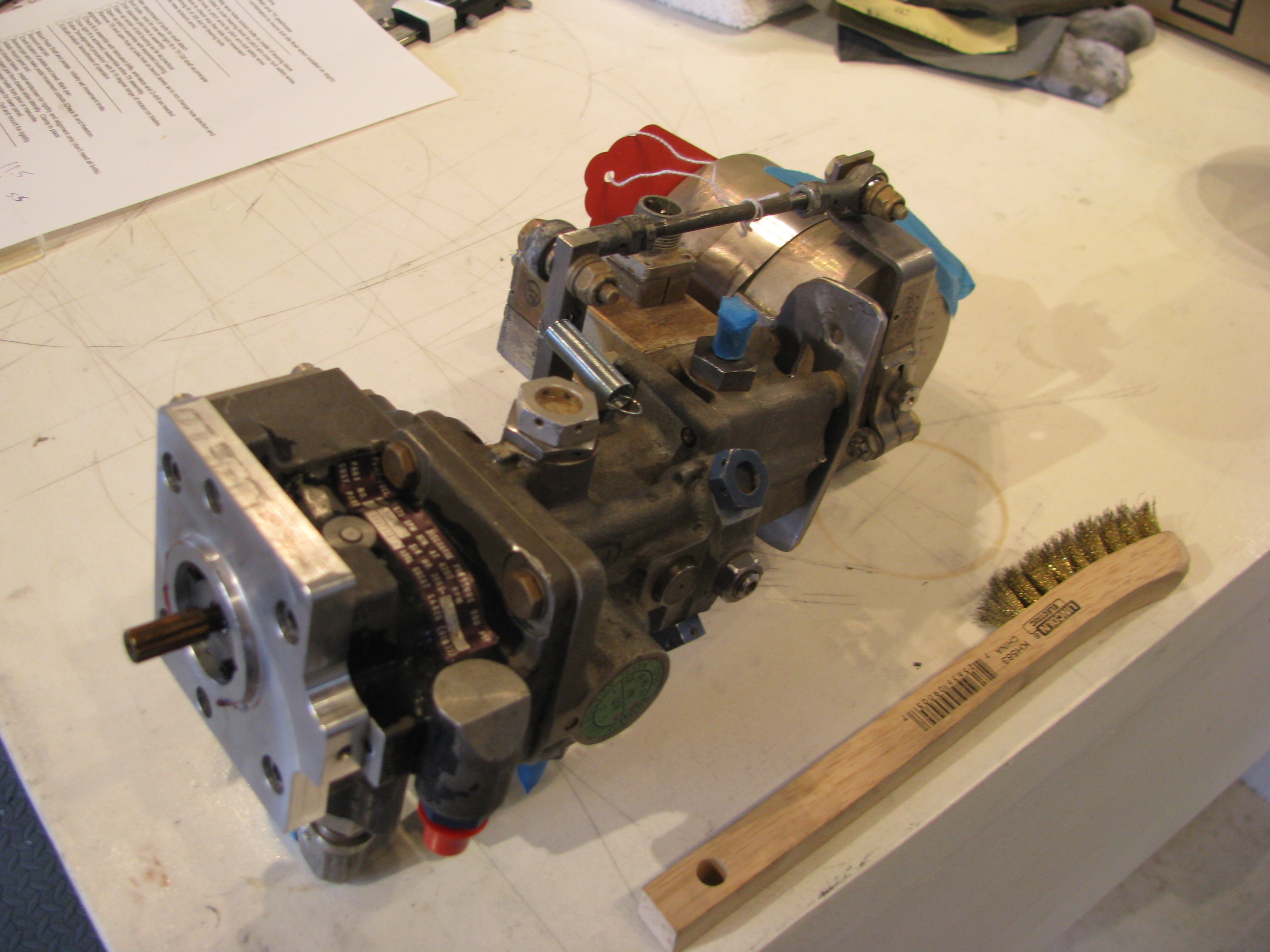
This is the fuel pump/control unit. That arm on the top is the infamous “delicate” throttle control arm. It is kind wimpy looking, but not tragically so. The surprising part is that the full travel from stop to stop is only about half an inch.
Though it is looks pretty tired, I am going to resist the temptation to take it apart to clean and resurface it. I’m quite sure that I would do more harm than good. It’ll just get cleaned and brushed off as an assembled unit, then reinstalled.
Speaking of more harm than good; BJ makes a point of having you make tick marks on the pulley and the mounting flange in the front of the gearbox to maintain alignment prior to removal. I did not realize that the conical center section is a piece separate from the pulley. I made my tick mark on the pulley, but when I pulled it off the shaft, the centering cone dropped out to the floor. I stared at it for 15 minutes to see if there was any hint of which position it was oriented in (1 of 6) by virtue of any witness marks on the mating surfaces, but could not. I will have to figure out where BJ was measuring when he said they were indexed to 0.003 to 0.005 of runout and remeasure to establish the orientation. Poop. This is my first mistake in a while caused by just not watching the videos closely enough.
Pedal Slots
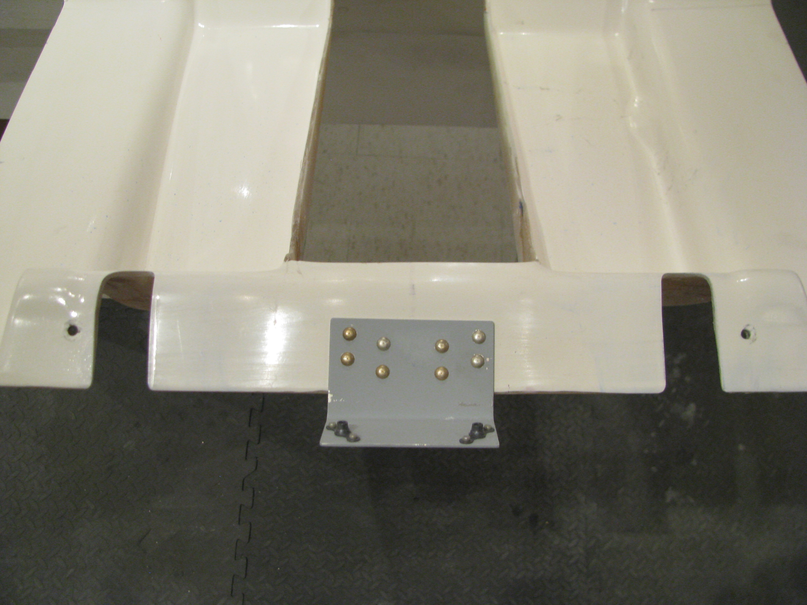
After not touching the body for a long time I am reassembling things so that I can fit the instrument pod.
Here I have cut the slots for the rudder pedals. Not trusting the scribe lines, I sort-of slid the pan on with the pedals in places so I could mark the locations for the cuts. Just using the scribed lines on the pan would have meant slots about half again wider than they really need to be since they were quite a bit offset from the actual pedal locations.
Turbine Install Start
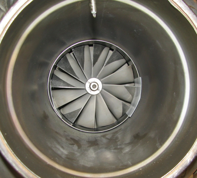
The Helicycle is powered by a Solar T62 turbine engine. It’s one of the primary attractions of this helicopter design. The T62 was designed as a ground power unit for the military for electrical generators and is used as the APU on a number of aircraft, including the CH47 Chinook.
In the Helicycle it is derated from its designed power output level of 160HP down to 90HP for reliability and longevity. Plenty of margin. Eagle R&D buys them surplus and refurbishes them including a teardown and dynamic balance.
As part of my effort to get multiple threads of effort going, I uncrated the engine and will begin tearing it apart in preparation for painting and mounting. You can see that I’ve started by removing the starter and a number of the fuel lines. Lots of pictures have been taken as each piece comes off and all the parts marked.
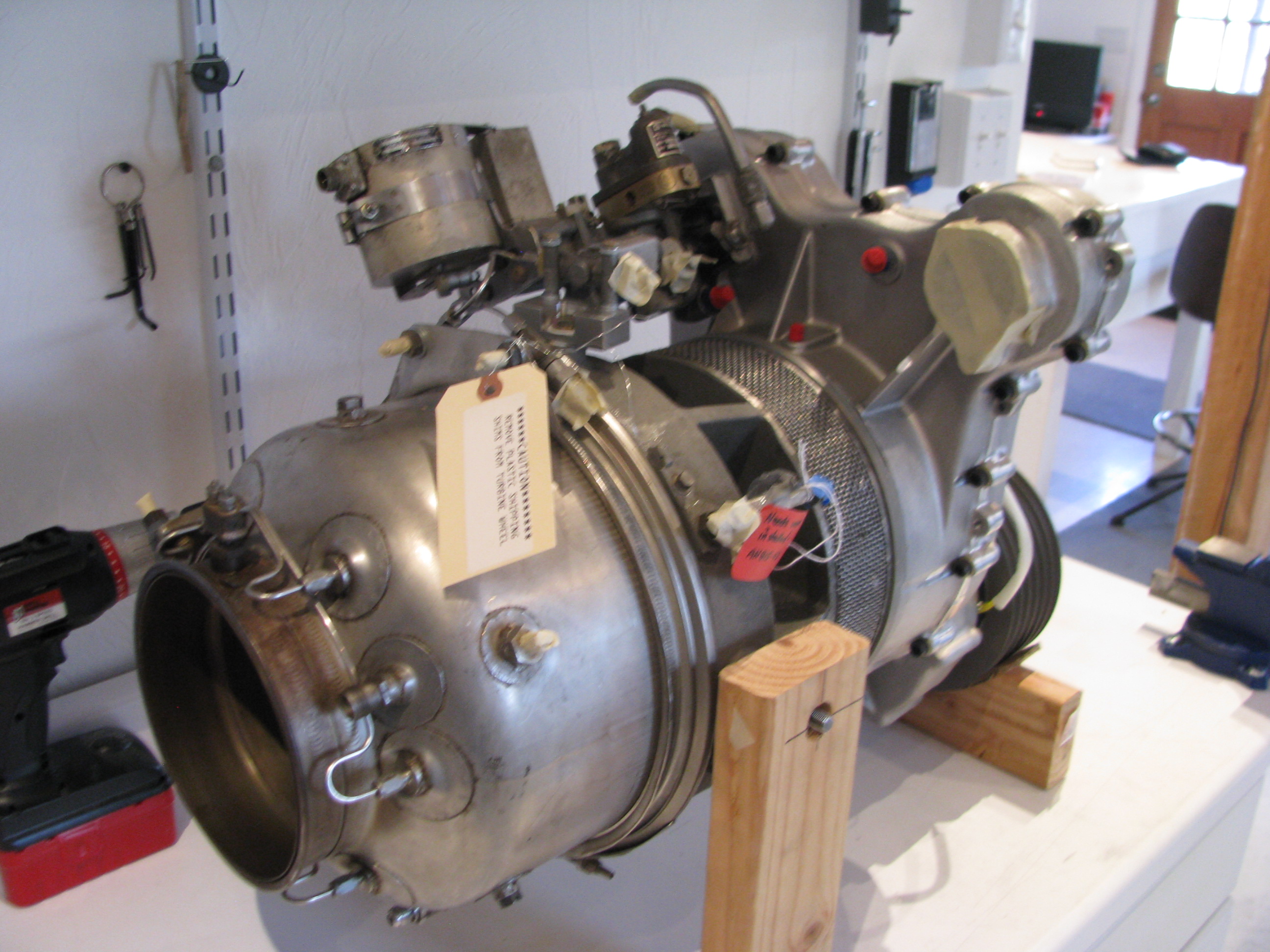
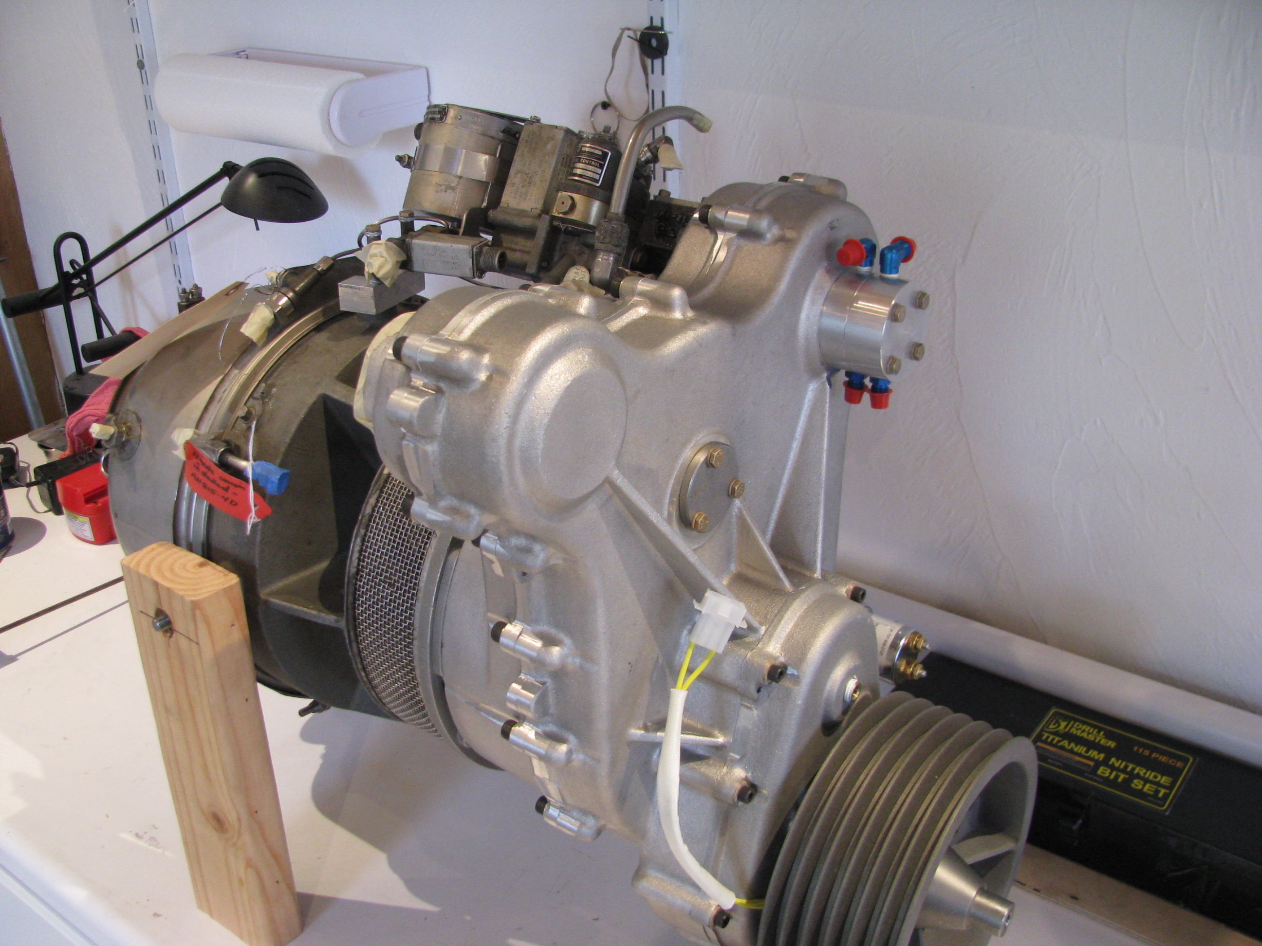
Mounting TR Assy
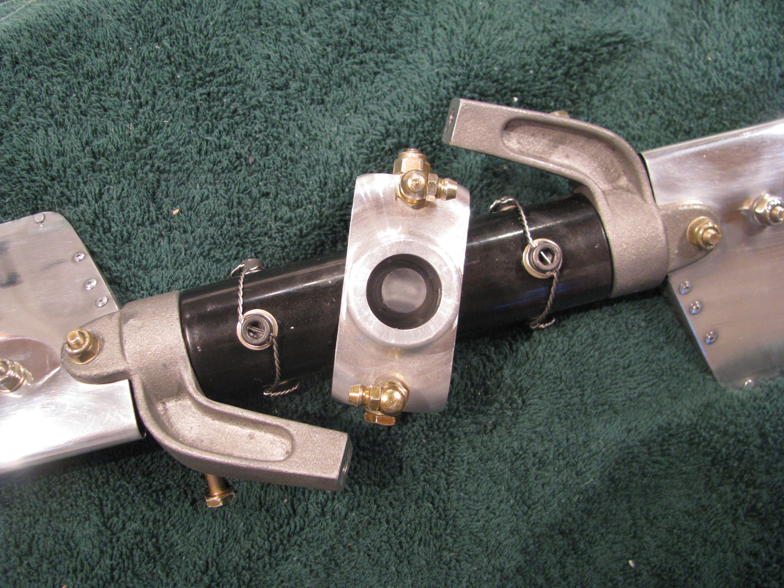
There are no matching prick punch marks.
Here is the business end of the tail rotor hub looking into the yoke. The plastic piece in the center is the “flapping restraint” plug. The allen bolts have been drilled and safety wired.
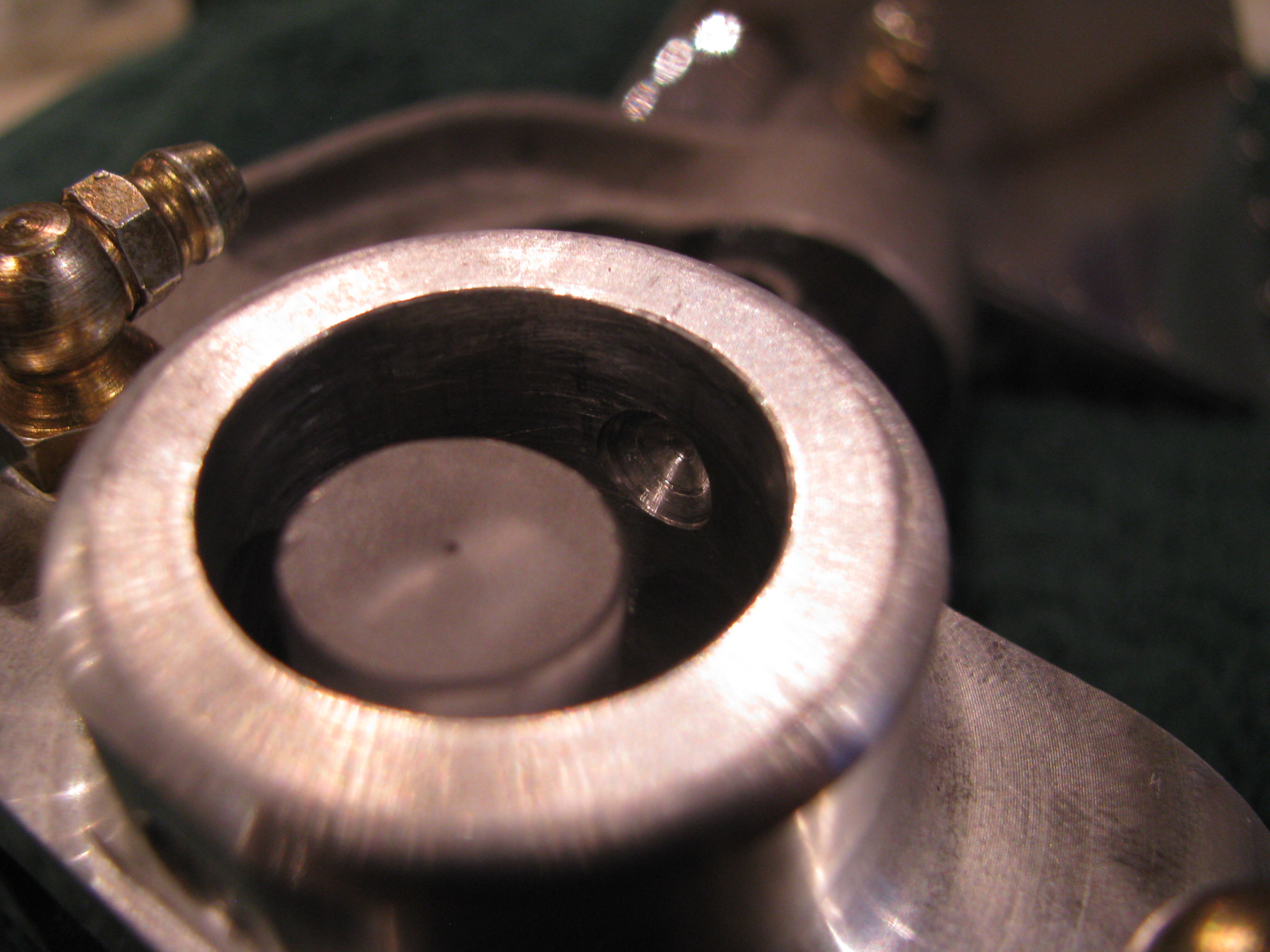
Looking into the yoke you can see the undrilled side. I searched the builders group and contacted Keith Southard whose kit was of the same vintage. He had the same situation and recommended a procedure for finish drilling this hole precisely with no slop.
The builder’s site is a great resource. Collectively there is a ton of information assembled and very knowledgable folks who are pretty responsive are active on it.
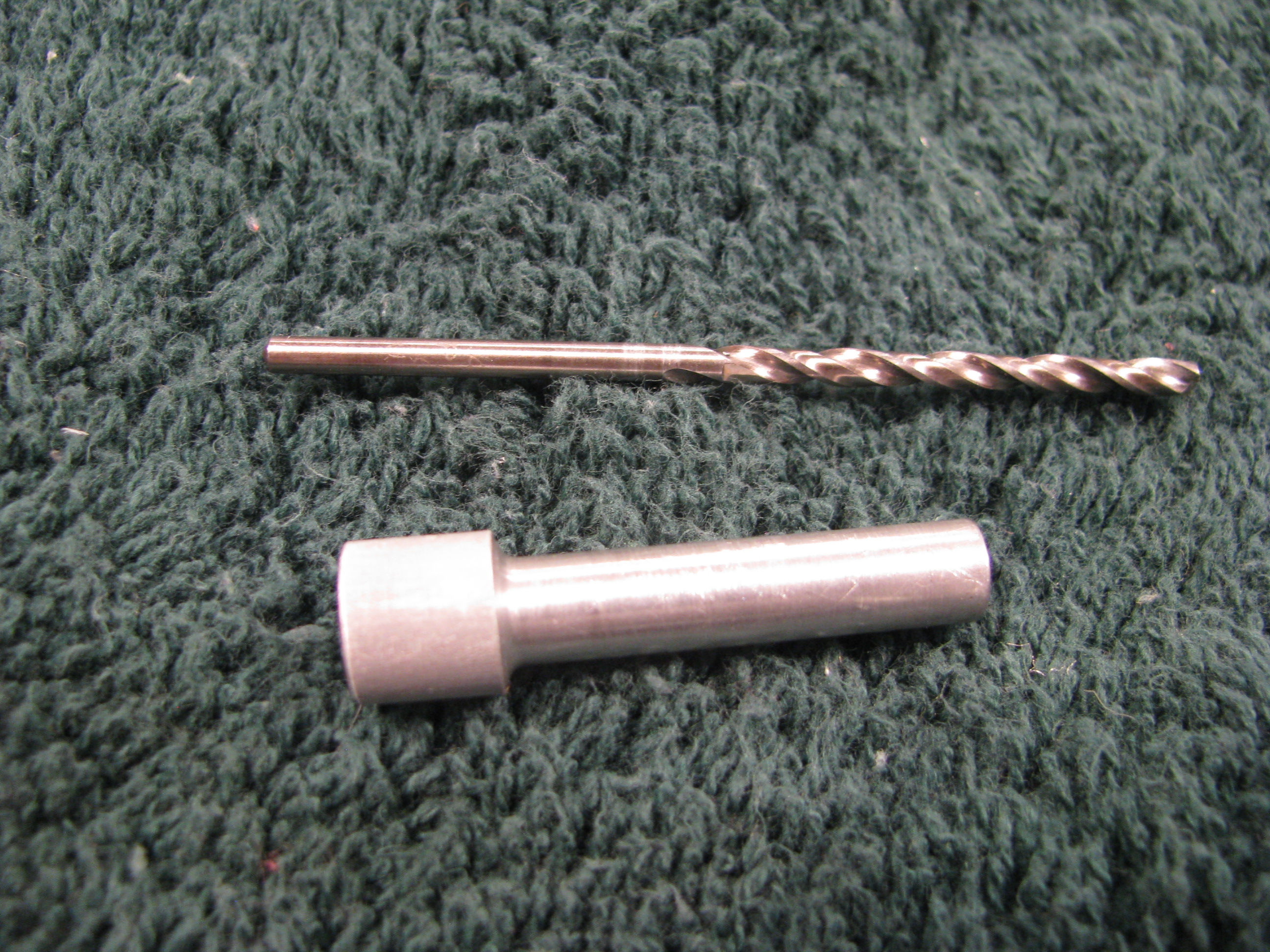
Start by making a drill bushing so a pilot can be drilled on the unfinished yoke side that will be perfectly centered. I chucked up an aluminum rod and lathed it down until it just barely and snugly fit in the hole on the drilled side. Then center bore a hole in the bushing for the pilot drill.
True to form, I messed up the first one, so I gave it a gentle chamfer and will use it as a drift to get everything lined up before employing the bushing and drilling for real.
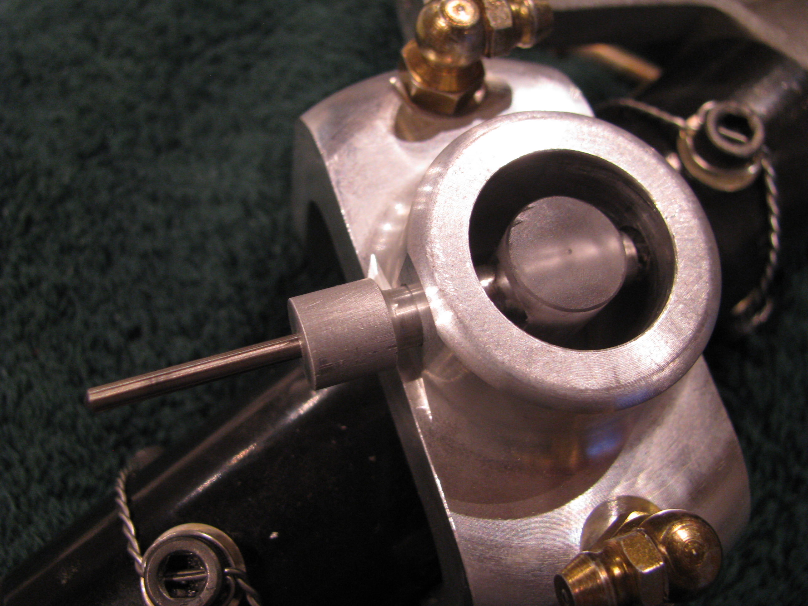
The idea is that I will drill the far side yoke hole with the drill bushing in assembly and then open it up slowly.
The final couple of steps, including the reaming, if necessary, will be done in assembly so there is absolutely no slop. I will procure a collection of the correct length AN4 bolts including some “close fit” bolts so I have a selection to choose from . It is surprising how different bolts in the same bag can have different diameters by +/- a couple of a mils.
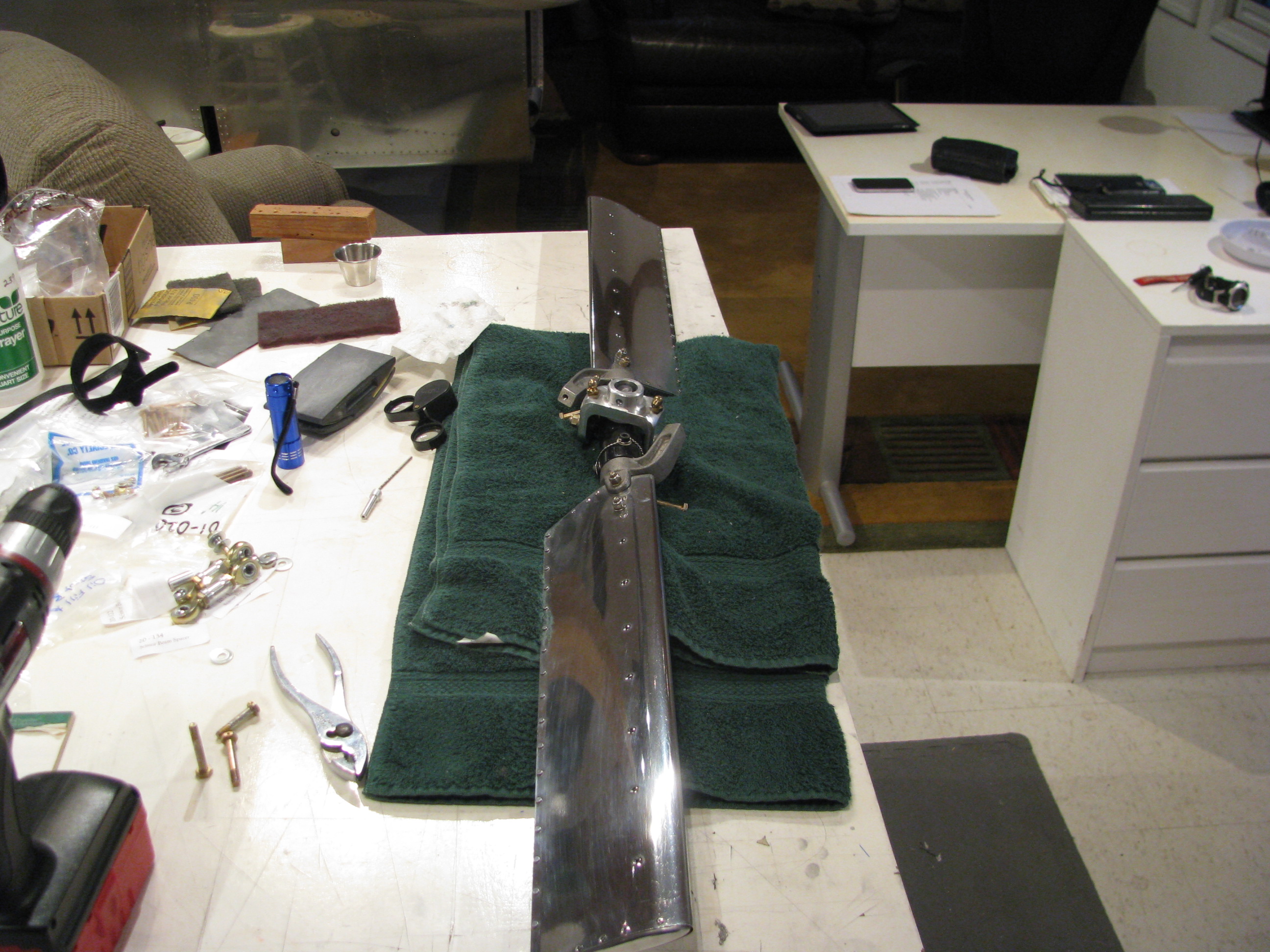
I also purchased kit of Nuvite Aluminum polish after reading Juan Rivera’s site and seeing his results. My plan is to polish the TR (no paint) as well as the TR drive shaft, main blades, and perhaps skids.
Now I am no expert. I just got the stuff. There are several different grades from the coarsest to the finest.
It doesn’t take a lot of brainpower, but it does take a lot of patience to get results. This is my first pass on the TR blades. It already looks better than anything I’ve ever polished before and I am sure I will repeat the sequence after all the handling of the TR is complete - so it will only get better.
Now I don’t think I’ll ever be as patient as Juan in getting the finish he shows on his web site, but it’ll still look good.
Polishing seems to have this bi-modal perception. You can get it looking shiny and very good. Stopping there would be fine. THEN , you decide to get mirror-like results and it’ll look like crap because once part of the surface shines up like a mirror, all the minor scratches and striations in the other areas become evident until the entire surface is perfect.
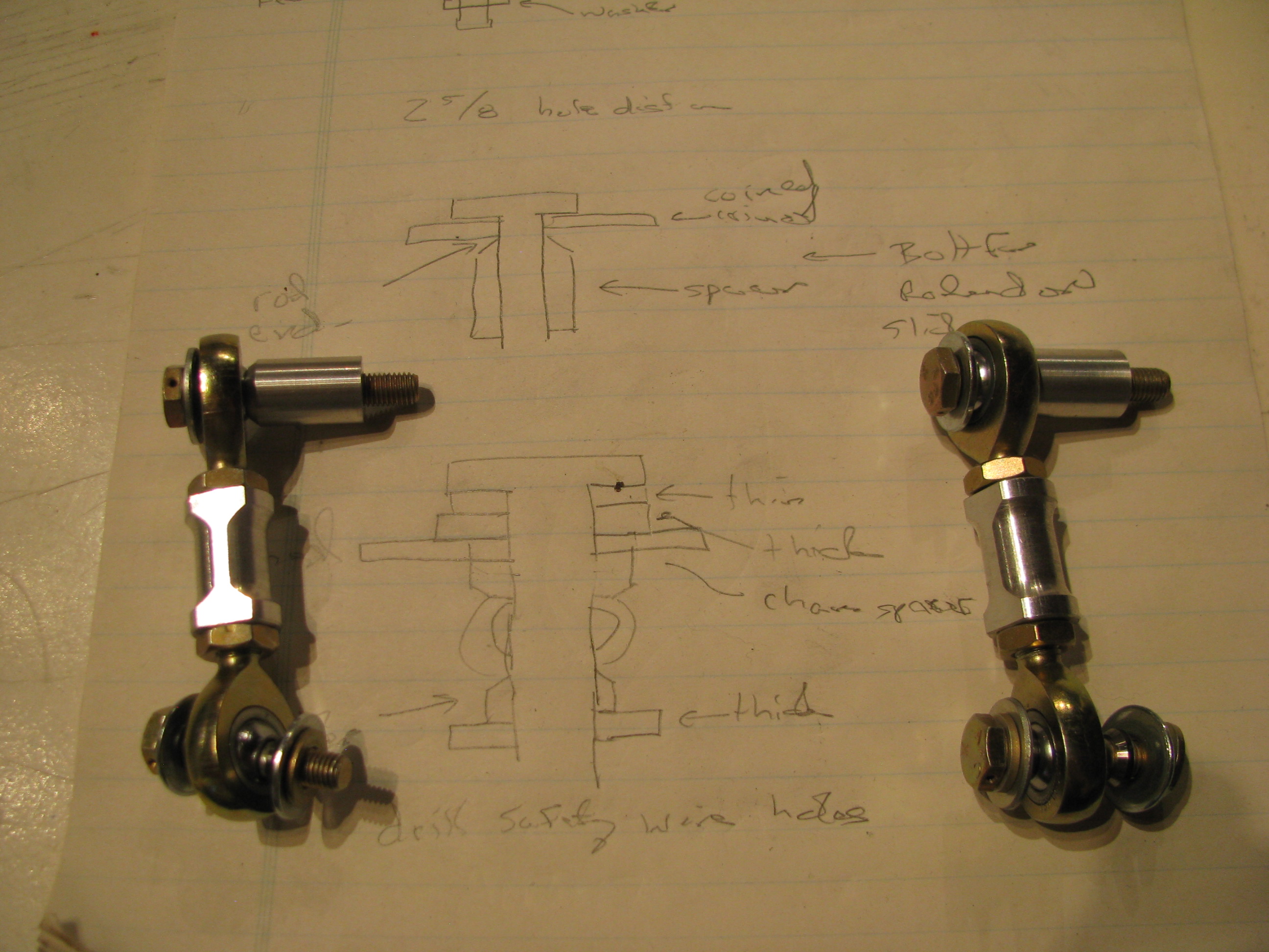
TR pitch link hardware. I blindly followed BJs instructions and cut 11/16 off the threads on the rod ends. You could probably leave another 1/16th or two on the ends (more threads to engage) as there is no way they will interfere with each other when screwed all the way in to the aluminum couplers.
I find that I am often making little sketches as I watch the videos (over and over) to have something to refer to in the shop.
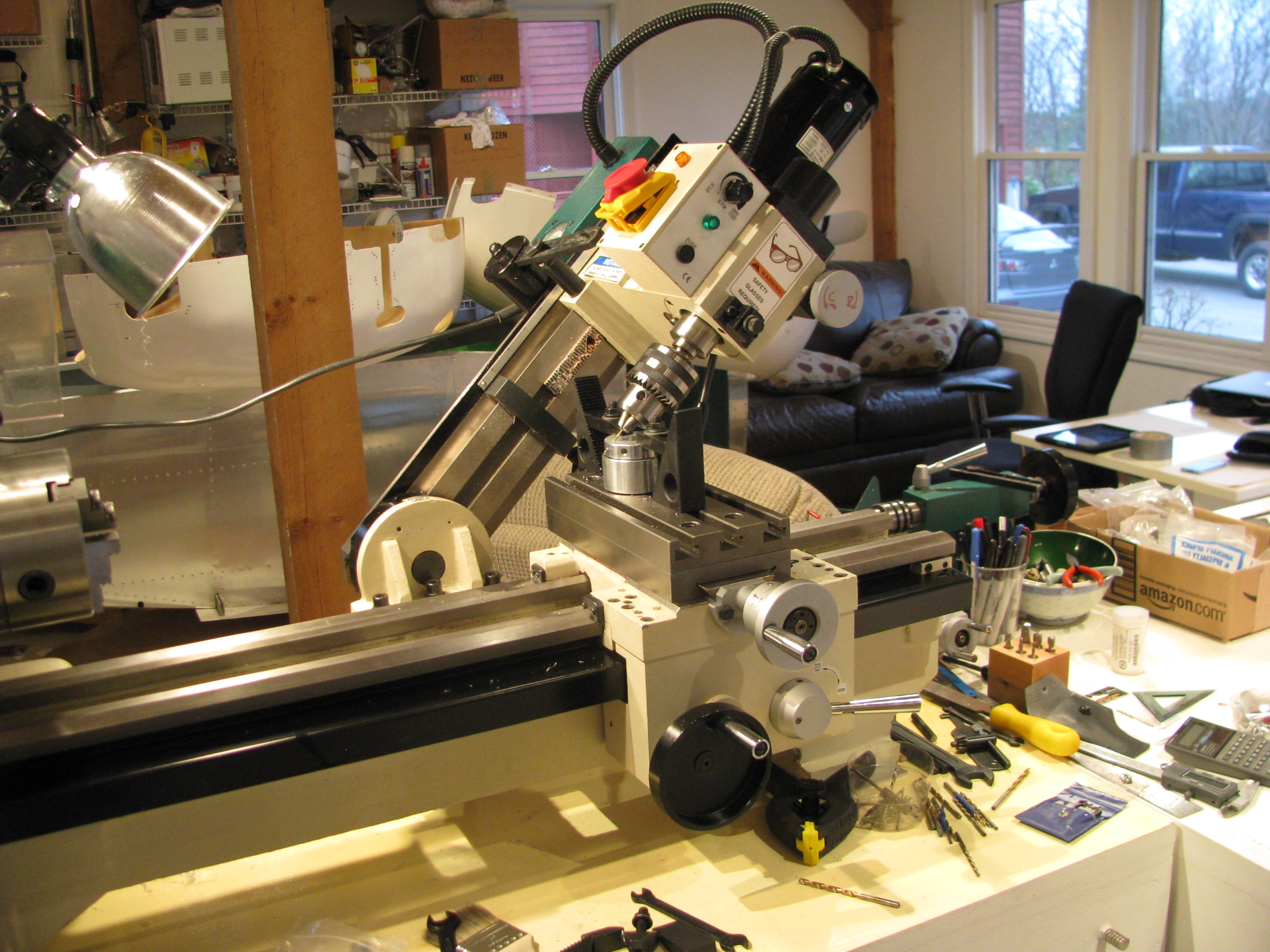
Drilling the safety wire holes in the slider would be a bit of a challenge without the mill. This is the first time I have ever angled the head over. The bearing block is then clamped to the surface in such a way that there is no side load on the bearing itself through the use of 3 large fender washers underneath the inner race.
As in most machining operations, the machine setup and work holding take 90% of the time. The actual metal cutting is but a few seconds.
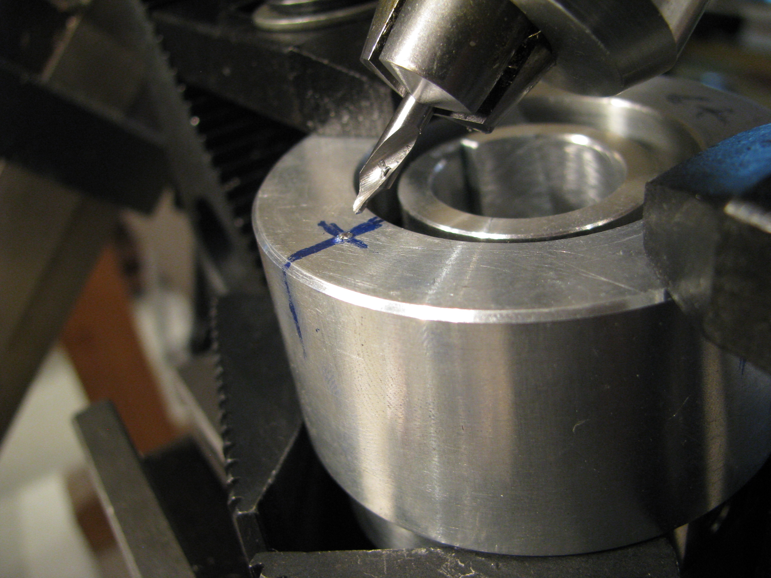
The outer race is supported underneath with some blocks so there is no side load on the bearing. A center drill is absolutely necessary for its stiffness. Drill just deep enough so that a normal bit will not jump out.
The first hole was a mess, the second better, and by the fourth it was perfect. I’m sure my second helicopter would be absolute perfection.
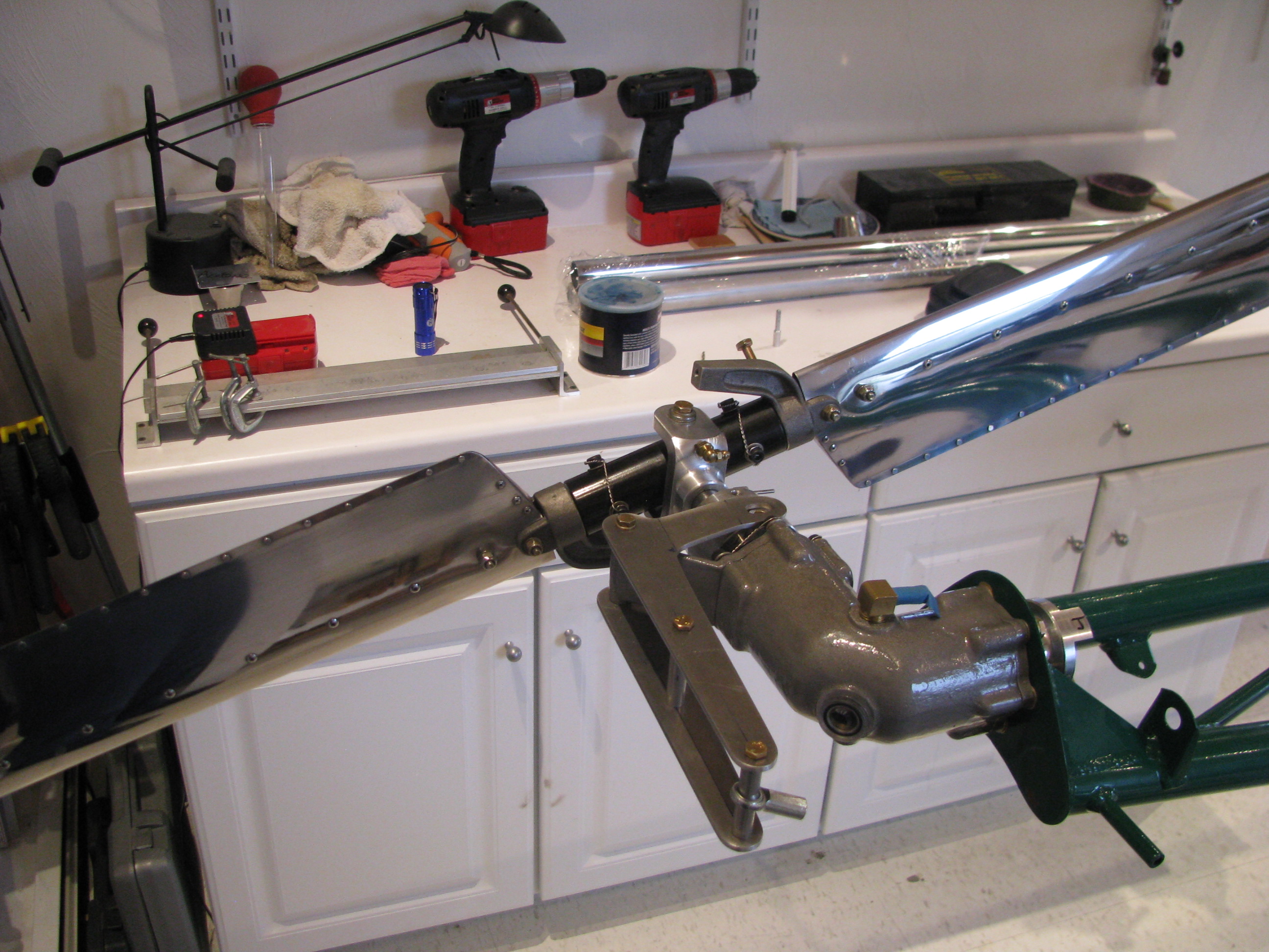
TR pre-assembled. Couldn’t resist spinning it around.
When I did this, however, I noticed that the slider bearing was not spinning cleanly. The bearing is defective and “ticks” as it spins. You can feel the “hitches” when you spin it by hand on the bench. I called Blake and he agreed that it didn’t sound right. It’s on its way back to Eagle to have a new one pressed in.
Tailrotor Start
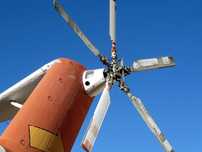
The pilot uses foot pedals to control the amount and direction of force exerted by the tail rotor to counter to the engine torque and thus control the direction the helicopter is pointing. Whenever the amount of power extracted from the engine is changed (climbing or descending), the amount of force needed from the tail rotor must be adjusted by the pilot to keep the helicopter pointing straight ahead.
The Helicycle kit comes with a largely assembled tail rotor since it is a very critical component and must be precisely constructed and balanced. My tasks consist of mounting, aligning and fabricating the control components.
Start by fabricating the control arms from 1/8” aluminum. Cut out according to the drawing, drill appropriate holes and open up a slot for the slider studs to ride in. I don’t know why, but I did this the hard way by drilling starter holes and opening up the slot with a file. As soon as I started I kicked myself for not setting up the mill and machining out the slot.
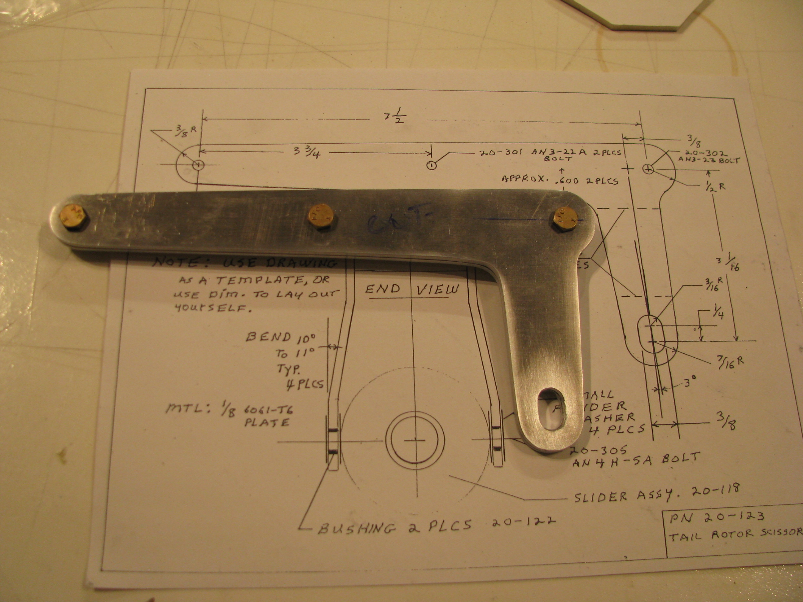
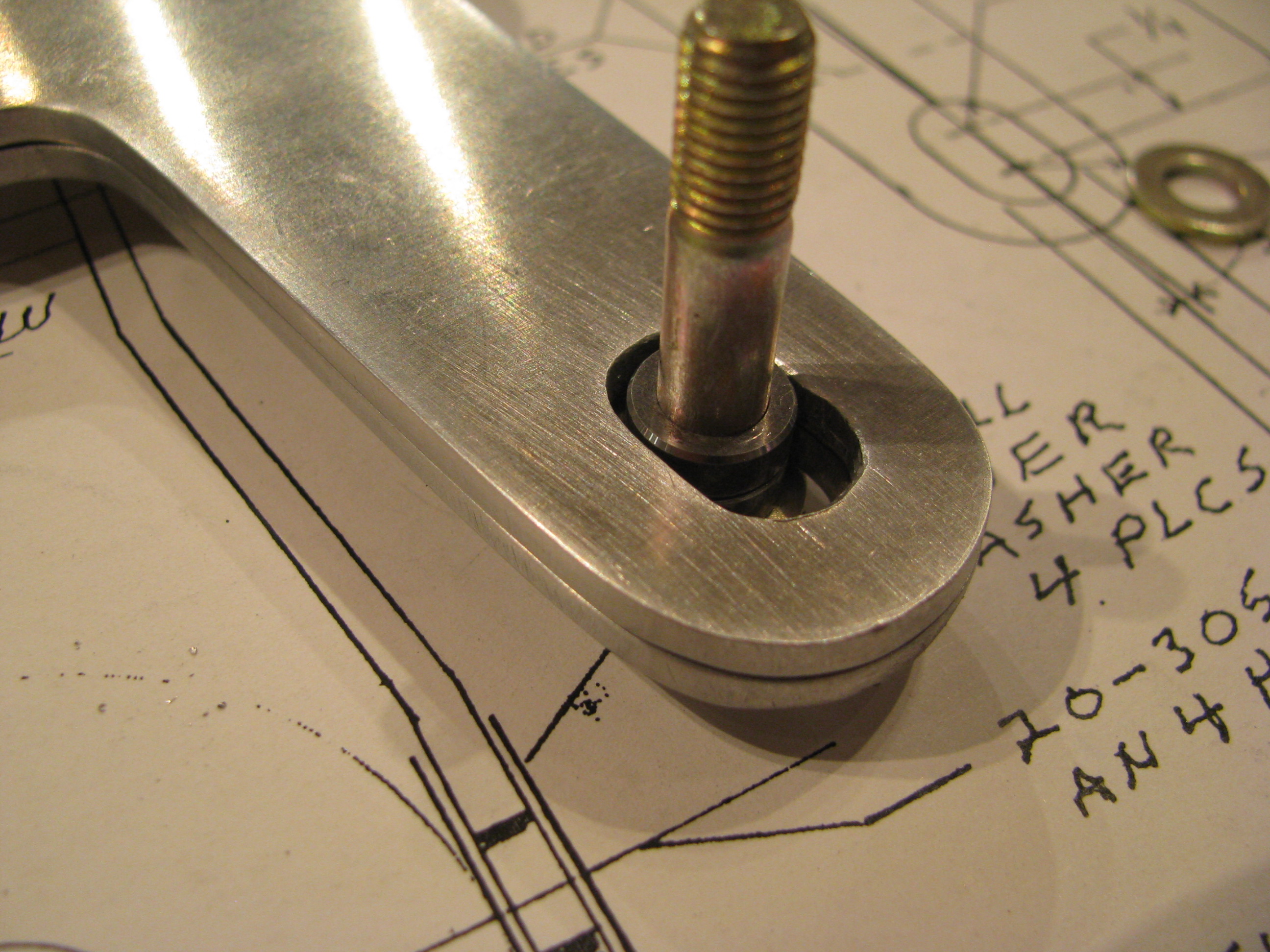
Doing it by hand is definitely not as precise. At one point in the slide there is a tiny bit of slop in the slot between the sleeved bolt and the aluminum. Probably 0.005” - Just enough to “tick” back and forth. I haven’t decided if this is enough to make me go back and fabricate new parts. I think I will see how much play there is when the whole thing is assembled. There are multiple bends and the slop may be “eaten” up by tolerances elsewhere. If there is any play when the tail rotor is installed I will re-fab the parts as I am guessing the tail rotor must be completely slop-free as it is subject to high frequency vibrations and much stress.
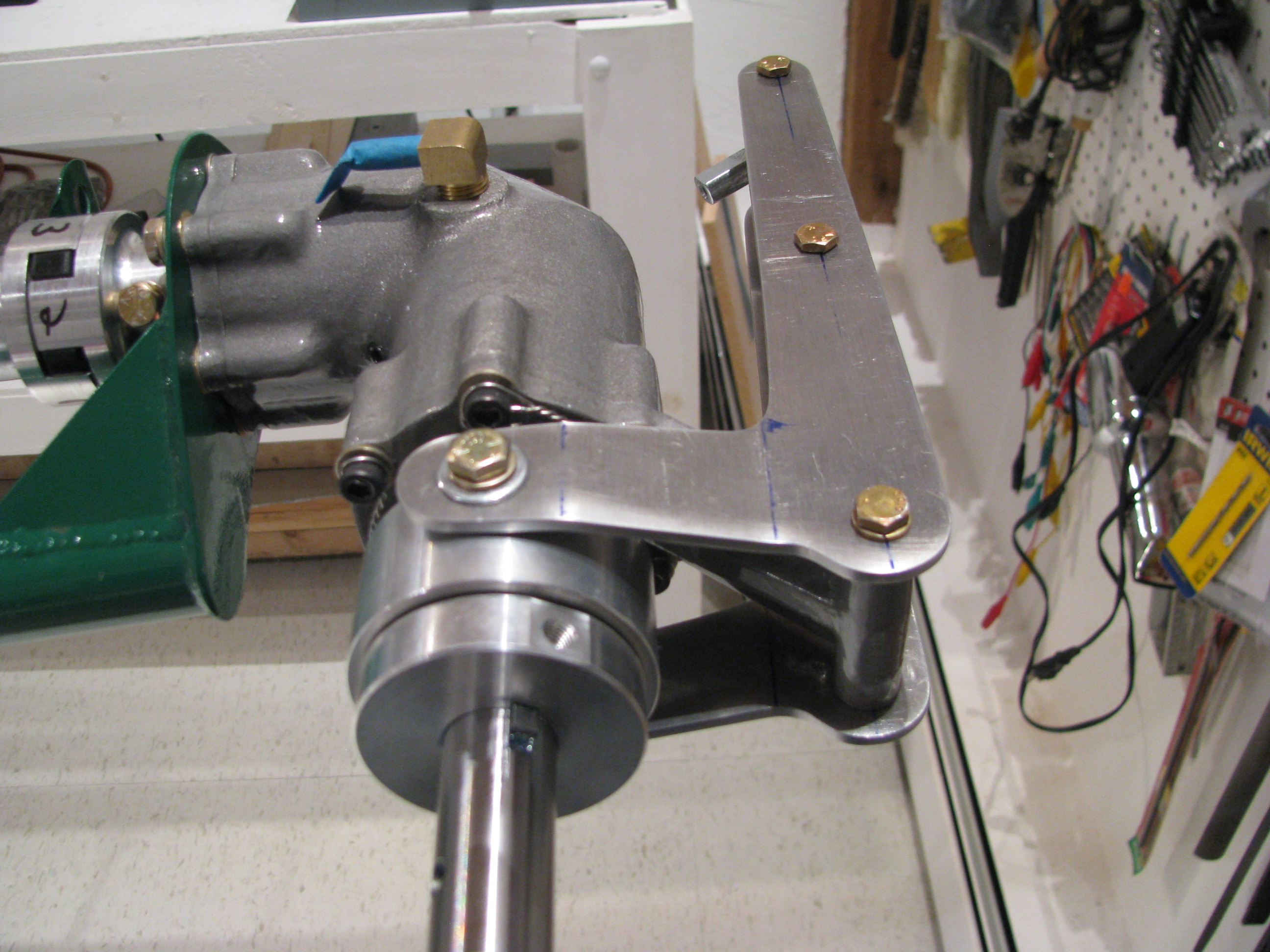
Bent and assembled the control arm scissors. Although it feels nice and snug, if you shwang the slider bearing back and forth you can feel a little play in the upper arm. I will fabricate new arms, but will use these for now for fitting and general assembly.
Bearing Block Mounting
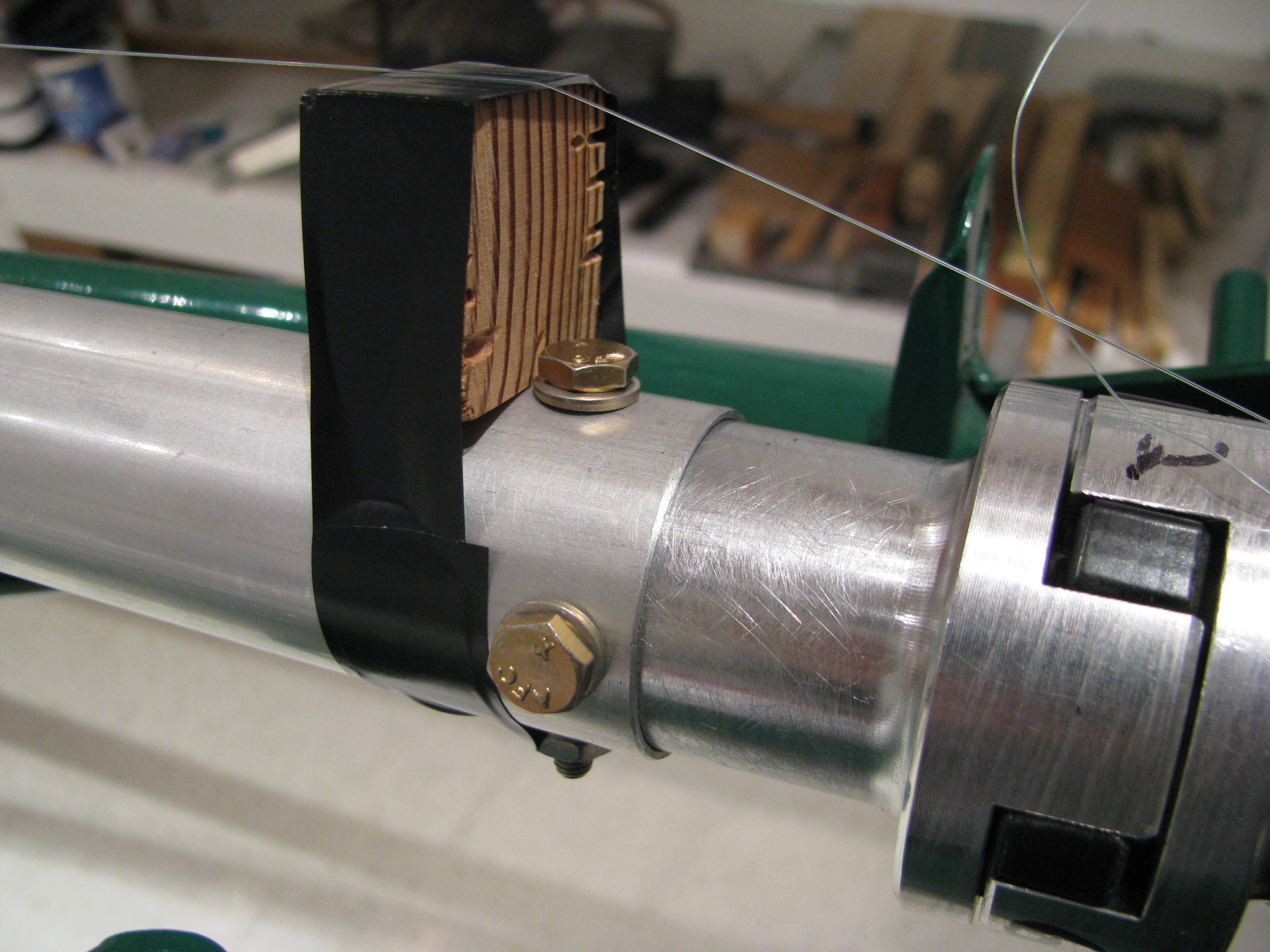
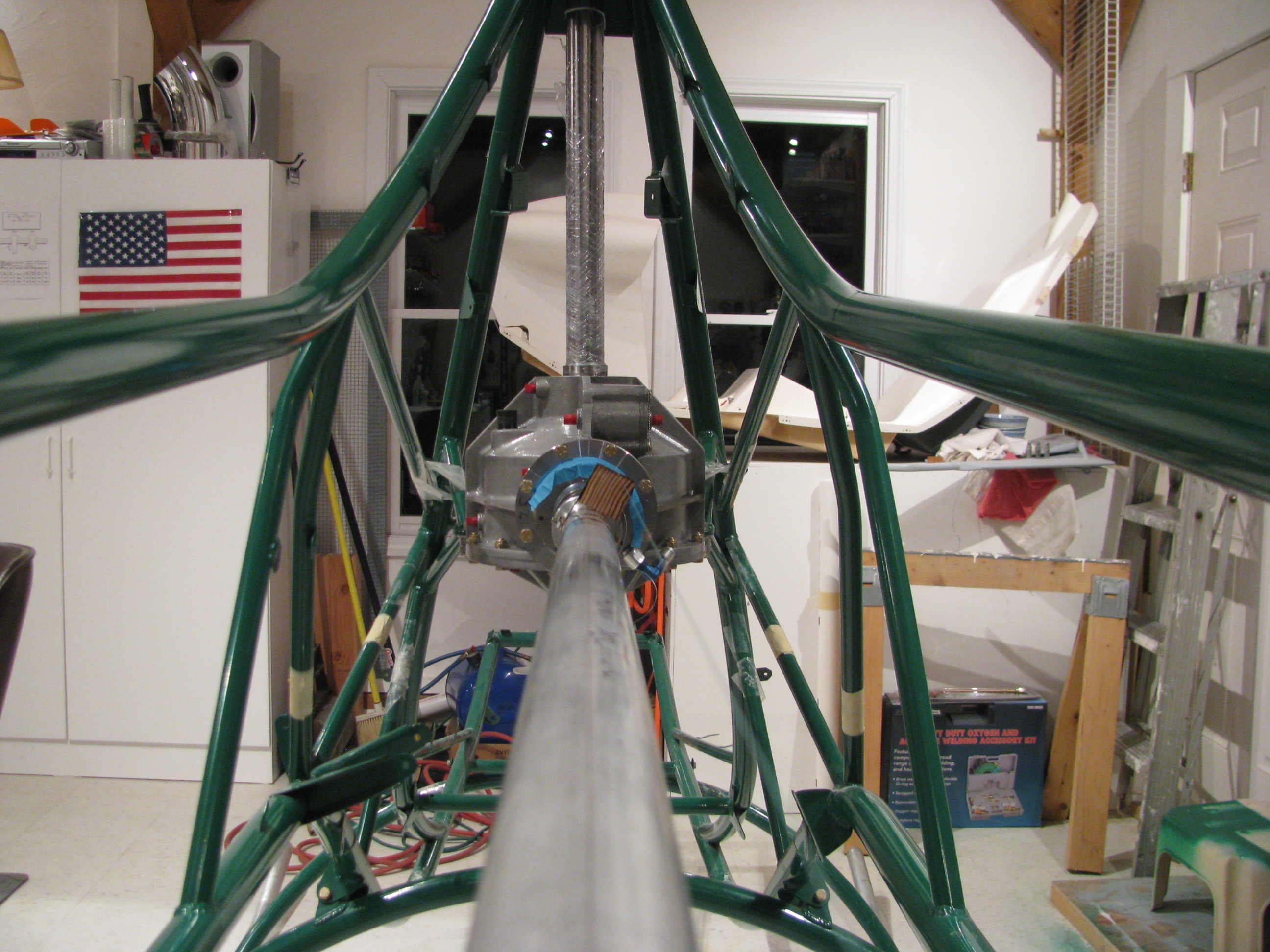
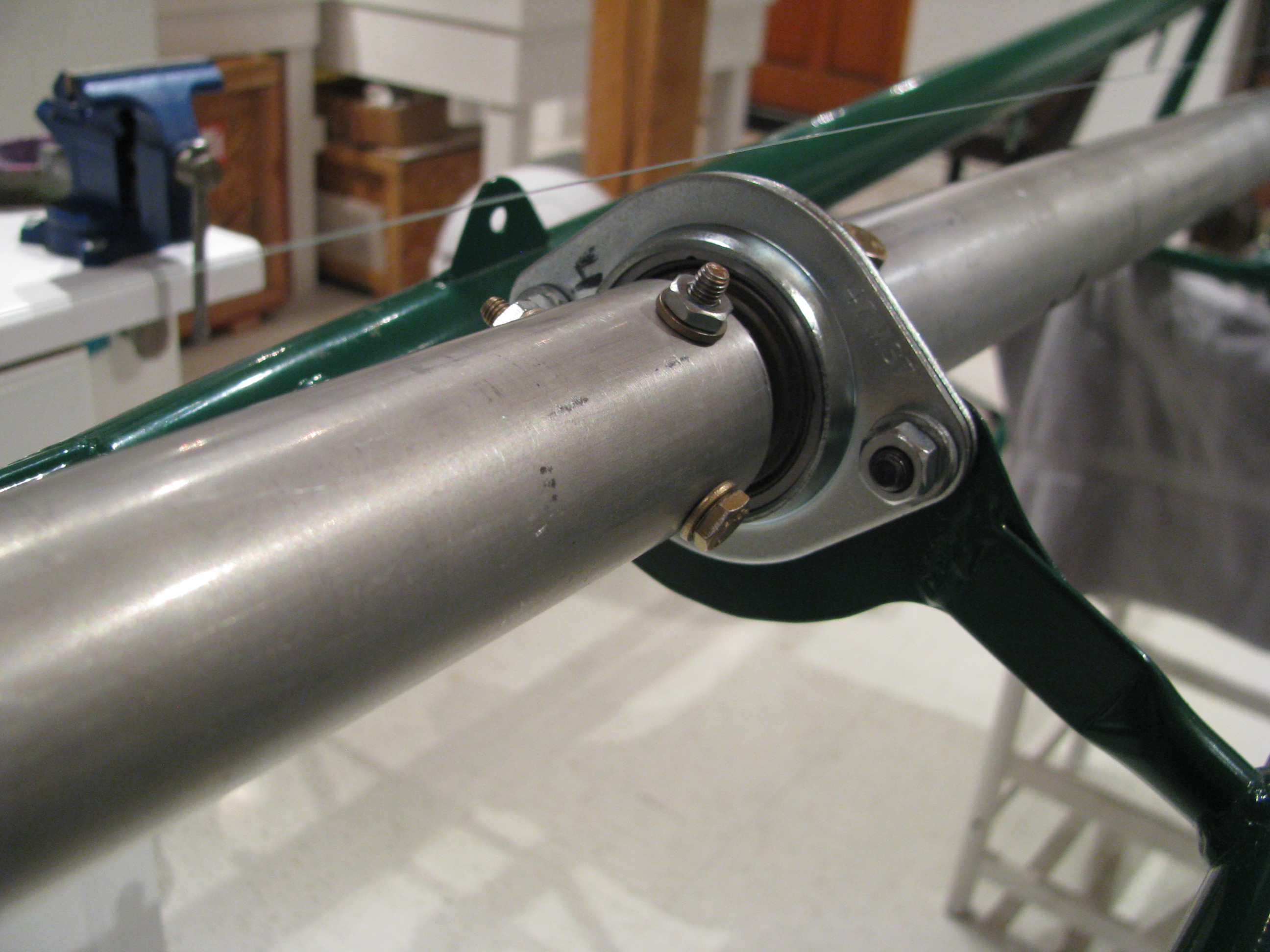
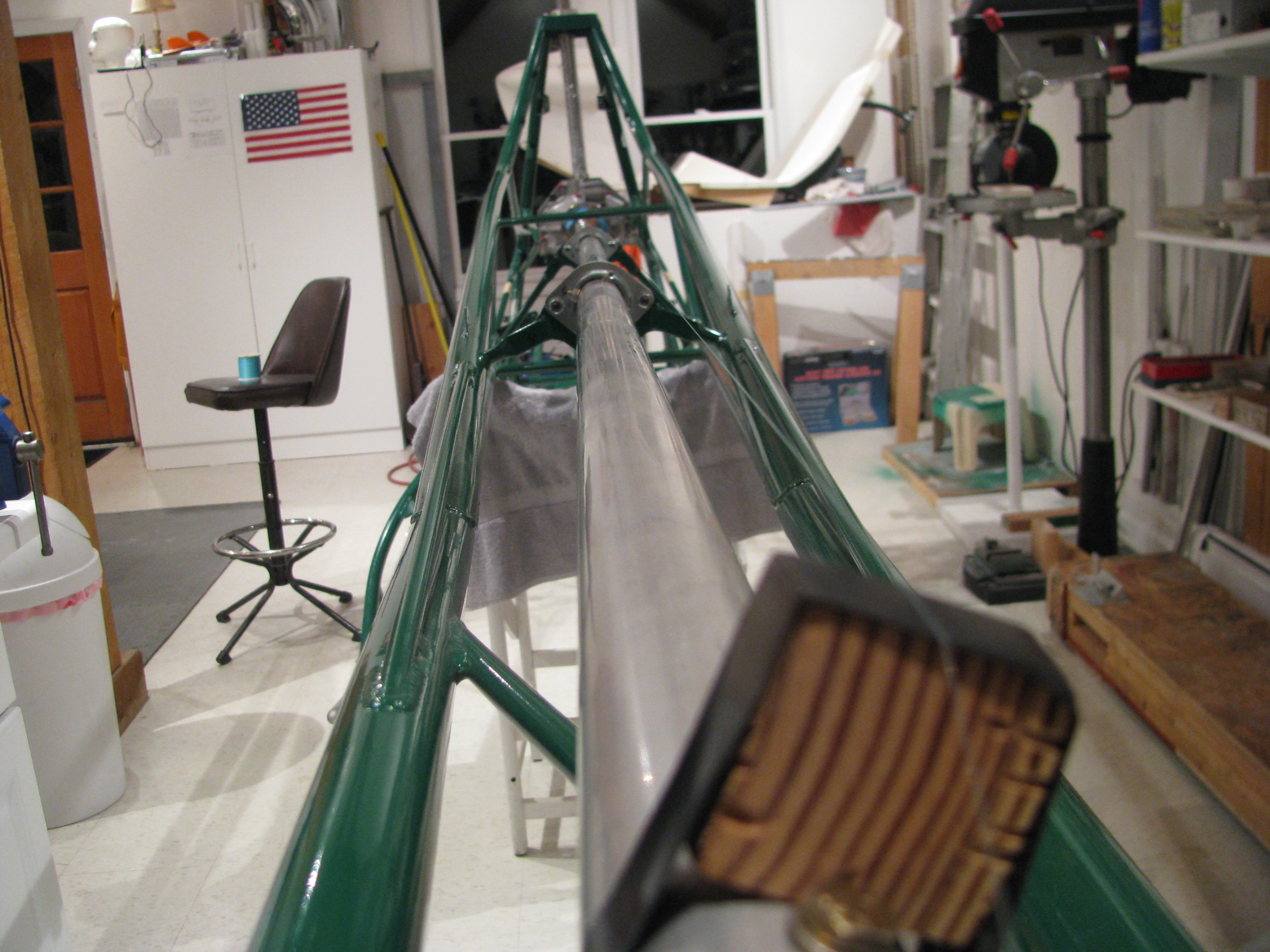
Almost done with gearboxes. Starting to look into the tail rotor.
More Heli-nerd stuff: I put together the entire tail rotor driveshaft, aligned it, and re-measured the clearance between the mating drive dog faces. Two different feeler gauges were used with different combinations of fingers to average out the errors, In all cases each measurement agreed within 0.001” of each other
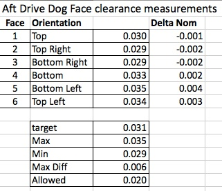
I am very pleased with the result at the rear. The shimming of the tail rotor gearbox is good and the drilling and fitting of the shafts didn’t change things that much. Cool. Everything is nicely centered on the nominal measurement and well under the allowed differential of 0.020”.
At the beginning of the video BJ gives you the target dimensions and at the end he sort of fudges and lets you know what you can really get away with. Happily I did not have to take advantage of the relaxed spec.
At the front shaft drive dog I got the following:
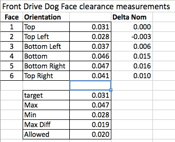
You can see that the front spacing is slightly larger and the differential is greater. The max differential is right at the (unrelaxed) spec limit. Not a lot can be done here since this is probably mostly due to the fact that the drive shaft is tilted up slightly from horizontal relative to the transmission and there is some built in twist to pre-compensate for the torquing of the frame under load. These should center out a little better when loaded, at least in the side-side differential department.
Overall I am pretty happy with this result as the distances are long and the potential for error is great. Just take your time and measure, measure, remeasure before drilling or cutting any metal.
Now, as with all other things on this machine, everything in this section gets pulled out and set aside until final assembly so I’ll be back to a stripped down frame again and my visitors will wonder if I am really doing anything other than napping in the shop.
Lee's first helicopter ride
LEE's First Passenger Flight.
Laser Measure TR Shaft
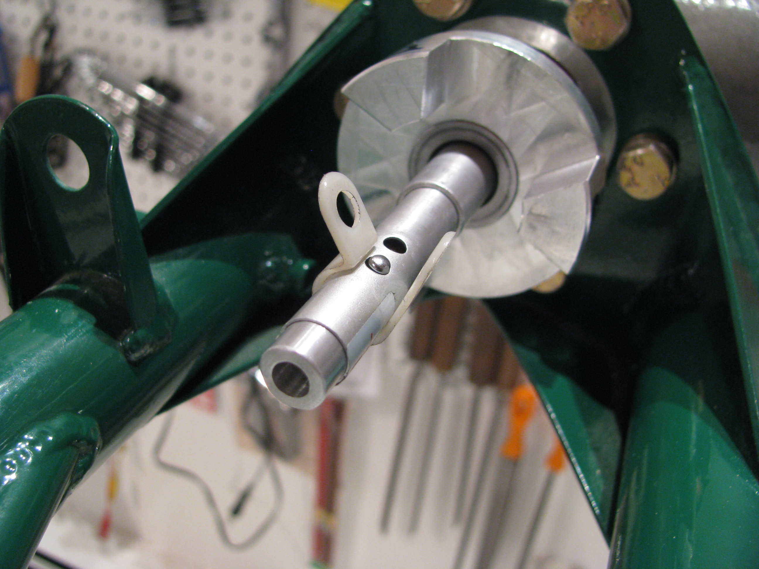
2/17/12 - I backed up a little. Even though I did BJ’s measurement procedure as detailed above, I realized that the two bearing blocks were only rough placed so the reference for measurements was not very exact to begin with. I fabricated a laser pointer alignment jig as others have done.
Get the smallest one you can find. Machine a spacer to sleeve it into the TR gearbox shaft. Realize that $2.99 laser pointers are not precision instruments. The beam is nowhere near coaxial, so as the shaft turns it circumscribes a circle at the far end. The shaft points to the center of that circle. It confirmed the CCW cant measured from the previous entry, but also showed a very slight downward point that I will have to shim out as well. That white plastic ring is a wire hanger just to hold the button down while measuring. I also machined a new front ring to hold the Laser diode more centered, but it didn’t help much. The beam is still canted off center. Leave a little slop in the sleeve so the pointer can be nudged to reduce the size of the circumscribed circle.
This is where it gets interesting only to Helicycle nerds. After using the laser to align the TR gearbox and adding 0.010 and 0.005 shims appropriately so the TR gearbox shaft is pointing as close as possible to the center of the output shaft on the main transmission I get the following:
1 - 0.031, 4 - 0.030 These are the top and bottom dogs. Delta=0.001”
2 - 0.029, 5 - 0.032 Top right and bottom left dogs. Delta=0.003”
3 - 0.028, 6 - 0.034 Bottom right and top left dogs. Delta=0.006”
So that’s a differential of 0.006” indicating an every so slight downward and CCW cant of the TR gearbox. This is much better than my initial attempt before fabricating my laser alignment tool and way tighter than the spec in the video. I should also note that I did the full string jig shaft alignment method prior to measuring
At the opposite end I measured the following clearances between the mating dogs at the main transmission end:
1 - 0.022, 4 - 0.044 These are the top and bottom dogs. Delta=0.022”
2 - 0.023, 5 - 0.043 Top left and bottom right dogs. Delta=0.020”
3 - 0.036, 6 - 0.032 Bottom left and top right dogs. Delta=0.004”
Not much can be done here. As expected this indicates that the main transmission is canted CCW as viewed from the top. This is expected as we built in some twist to balance out the expected torque. Also, the TR shaft is tilted slight up relative to the main xmission, so there’s not much that can be done there either.
I should note that nothing has been drilled yet, this is just placement and measuring to make sure everything fits and is spaced properly prior to drilling the shaft tubes to the bearings and dogs. Next up is to work out the appropriate bolt spacing and to figure out how I am going to drill the bolt holes perfectly.
Finally the Ticket!!!

Finally and at long last! As of this afternoon the key words “ROTORCRAFT HELICOPTER” are now added to my ticket. I ended up spending far more time in training to get my helicopter license than my fixed wing. I logged about 65 hours in training to get here.
The exam and checkride process was very detailed. About 2 hours talking helicopters for the oral portion, and 1.4 in the air. Very thorough. We must have gone through every maneuver in the book. The most challenging was the surprise power cut on downwind. Had to do an auto “for real”. Decide where to go and execute. I elected to do a 180 auto back to the runway based on where I was - and it all worked out OK, though the added second of recognition when it is a “surprise” allows the rotor RPMs to drop a lot lower than when you’re doing them for practice. That was an eye opener. I caught it in time, and the 180 degree turn helped bring the RPMs back up quickly. It even surprised me just how automatic lowering the collective was. Once I got over the “Hey, you can’t do that...” reaction.
Much like the fixed wing license, I am quite conscious that simply holding the license does not make me an expert, but merely minimally competent and equipped with the tools to help prevent me from doing myself in while piloting one of these unlikely machines.
I will try to stay current, but will definitely be back for a bunch more training prior to attempting to pilot the Helicycle.
Tail Rotor Shaft Start
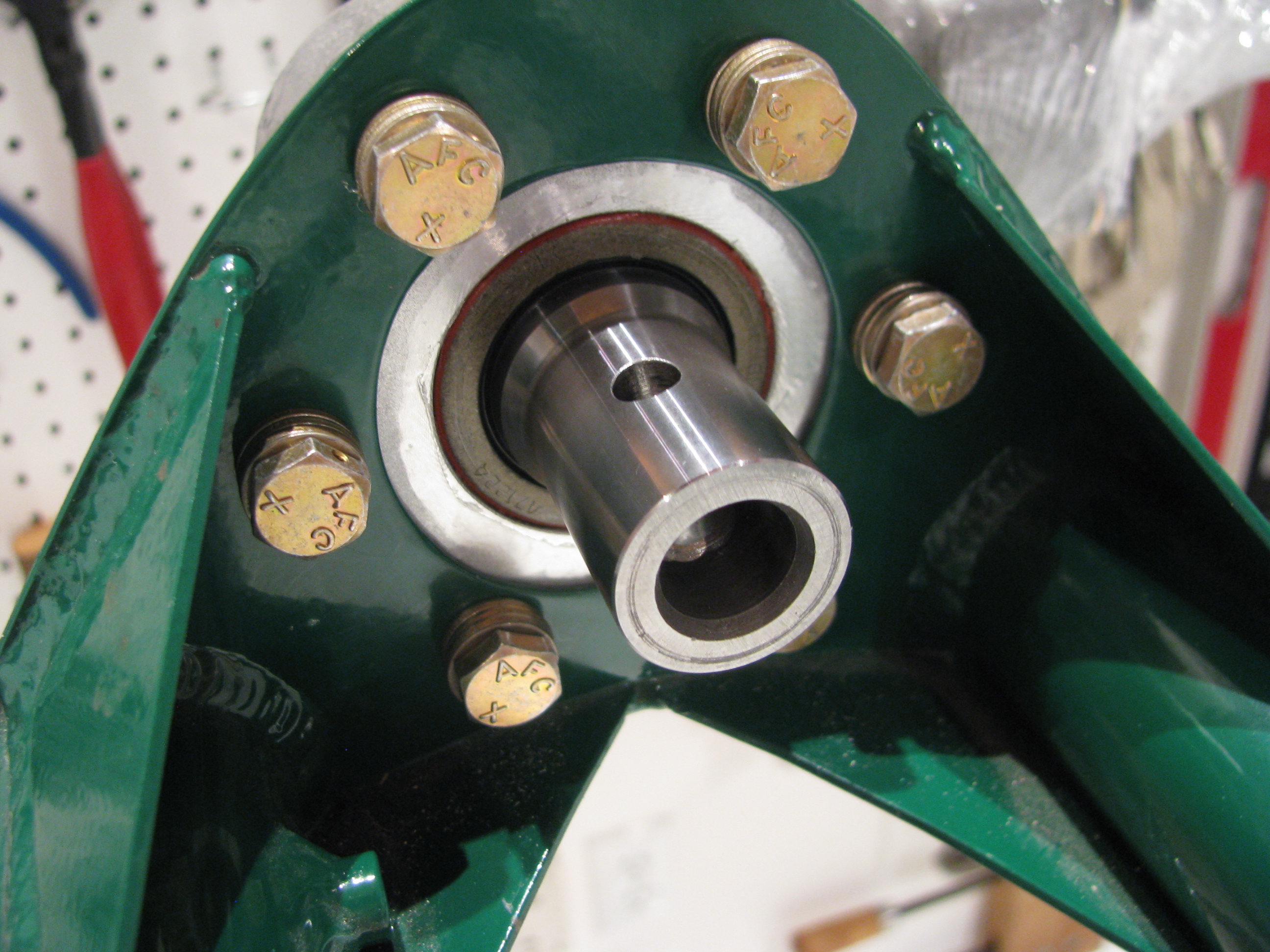
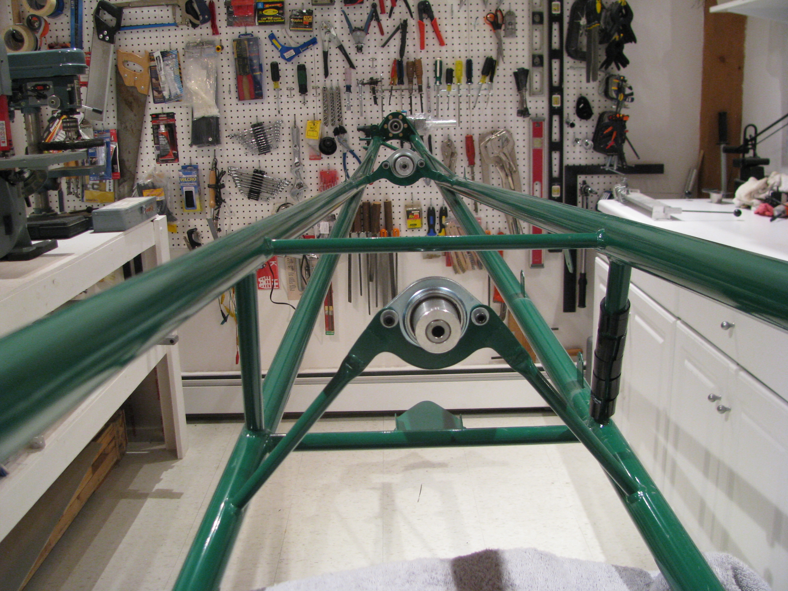
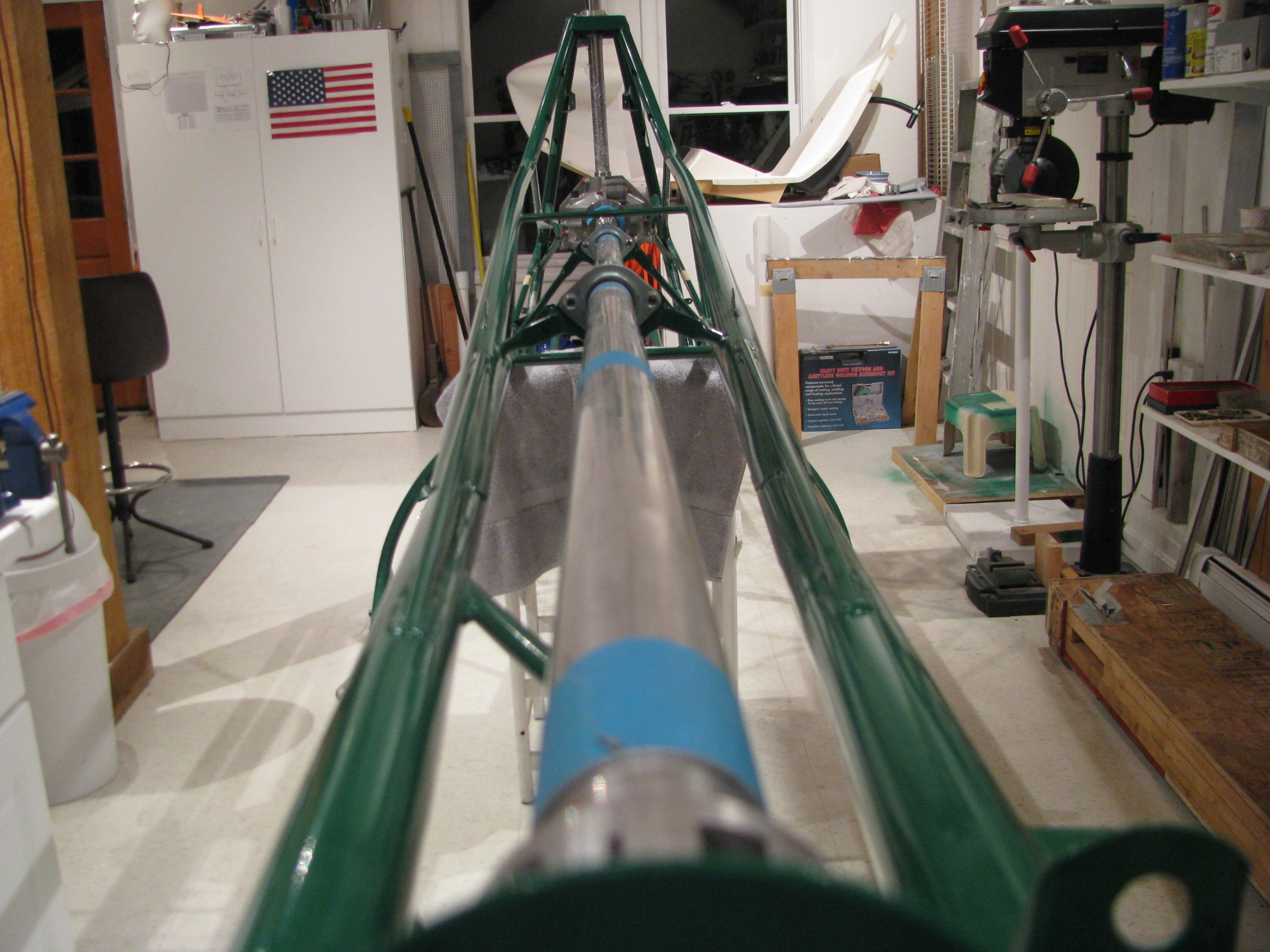
Shaft sections are cut and first order fitting completed. A lot of fiddling required to get the lengths right. Fit is very tight over the bearing inserts, so it takes some sanding/polishing and a daub of grease to get them to slide on. That will be mostly removed on final assembly. There is a definite sequence of assembly required. Start at the front since the bearing blocks all mount from the rear.
Small cuts and sanding, then retry. Very time consuming.
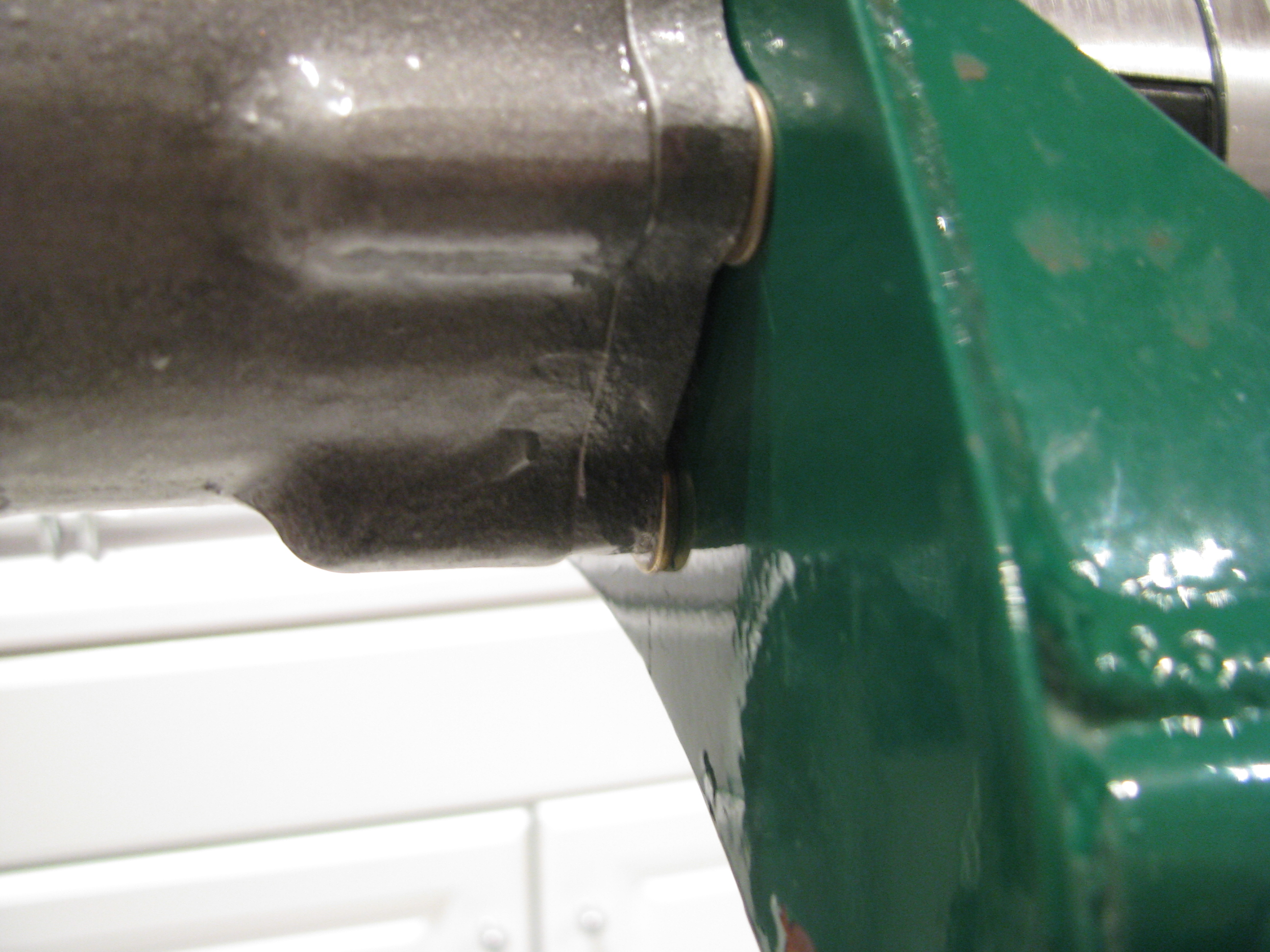
To get the TR gearbox aligned required a thick washer on the bottom and a thin in the middle, and none at the top on the outside of the frame between the gearbox and the frame. This is almost the opposite of what BJ required in the video. Like his example, almost no left/right differential was required, mostly up/down.
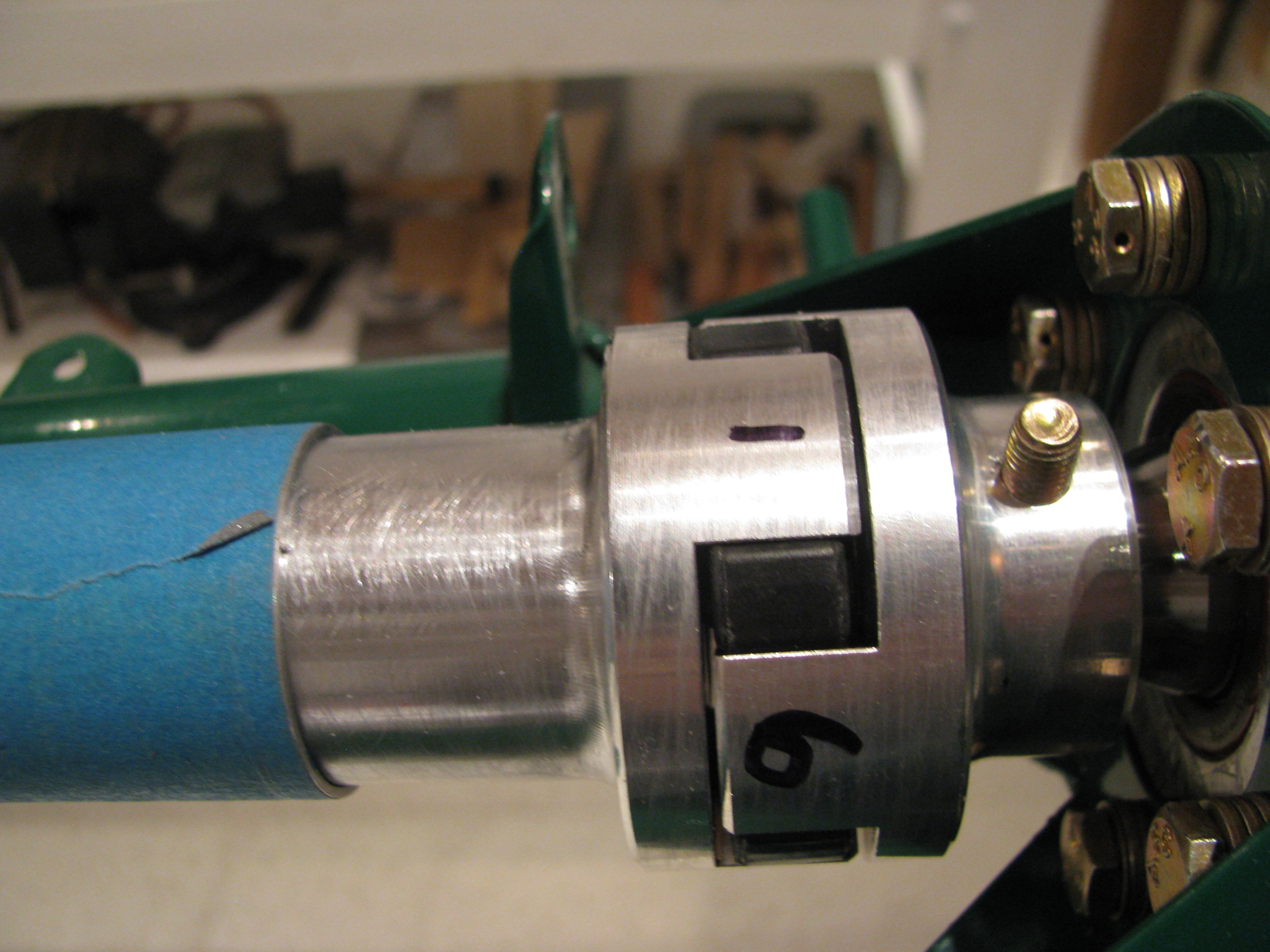
At the TR gearbox the distance between the dogs and the mate is measured. The goal is less than 0.020 differential side-side or up/down. I numbered the ears and measured the following:
1 - 0.030, 4 - 0.029 delta = 0.001
2 - 0.025, 5 - 0.035 delta = 0.010
3 - 0.024, 6 - 0.034 delta = 0.010
It is numbered this way because measurements 1 and 4 are on opposite sides, 2-5 are opposite, and 3-6 are opposite. The greatest difference is 0.011 between any two and there is definitely less than 0.020 difference, so I am satisfied (almost). I may try to add my thinnest shim stock to the 3 right side bolts to try to remove the slight CCW cant (viewed from top) and get it as close to perfect as possible. Now is the time as it’s unlikely I will revisit this until final assembly.
Shimming Hood Bearing
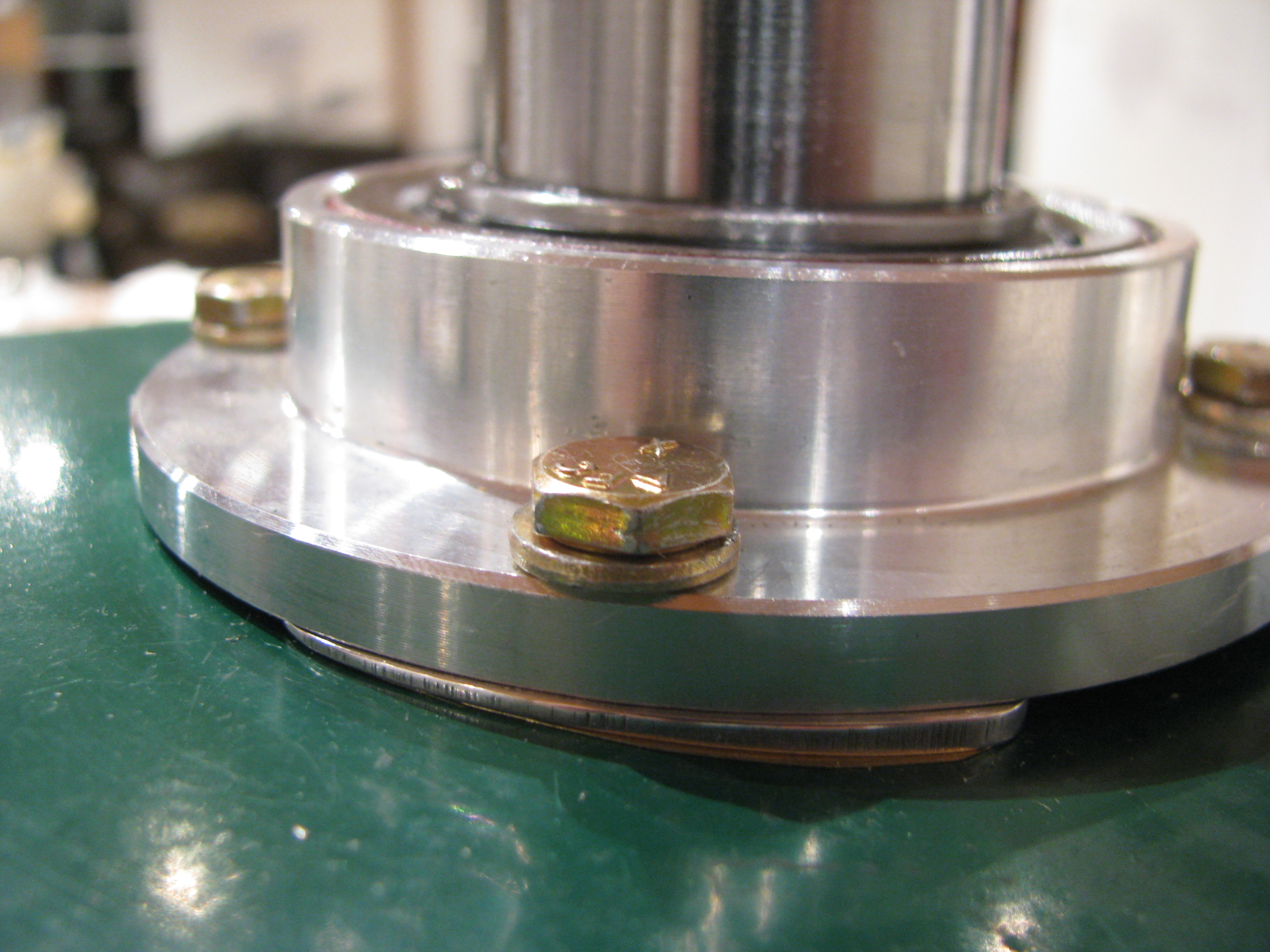
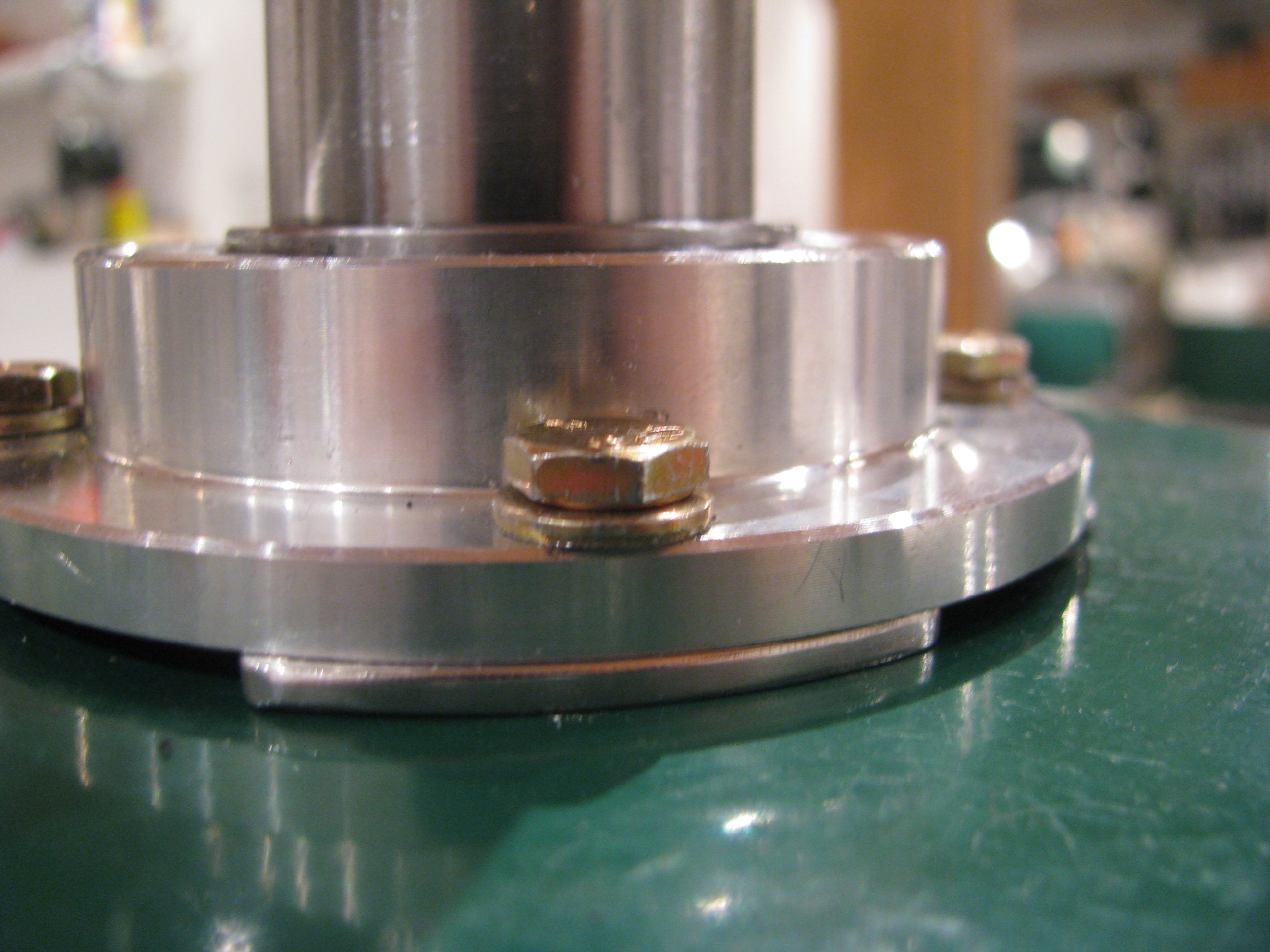
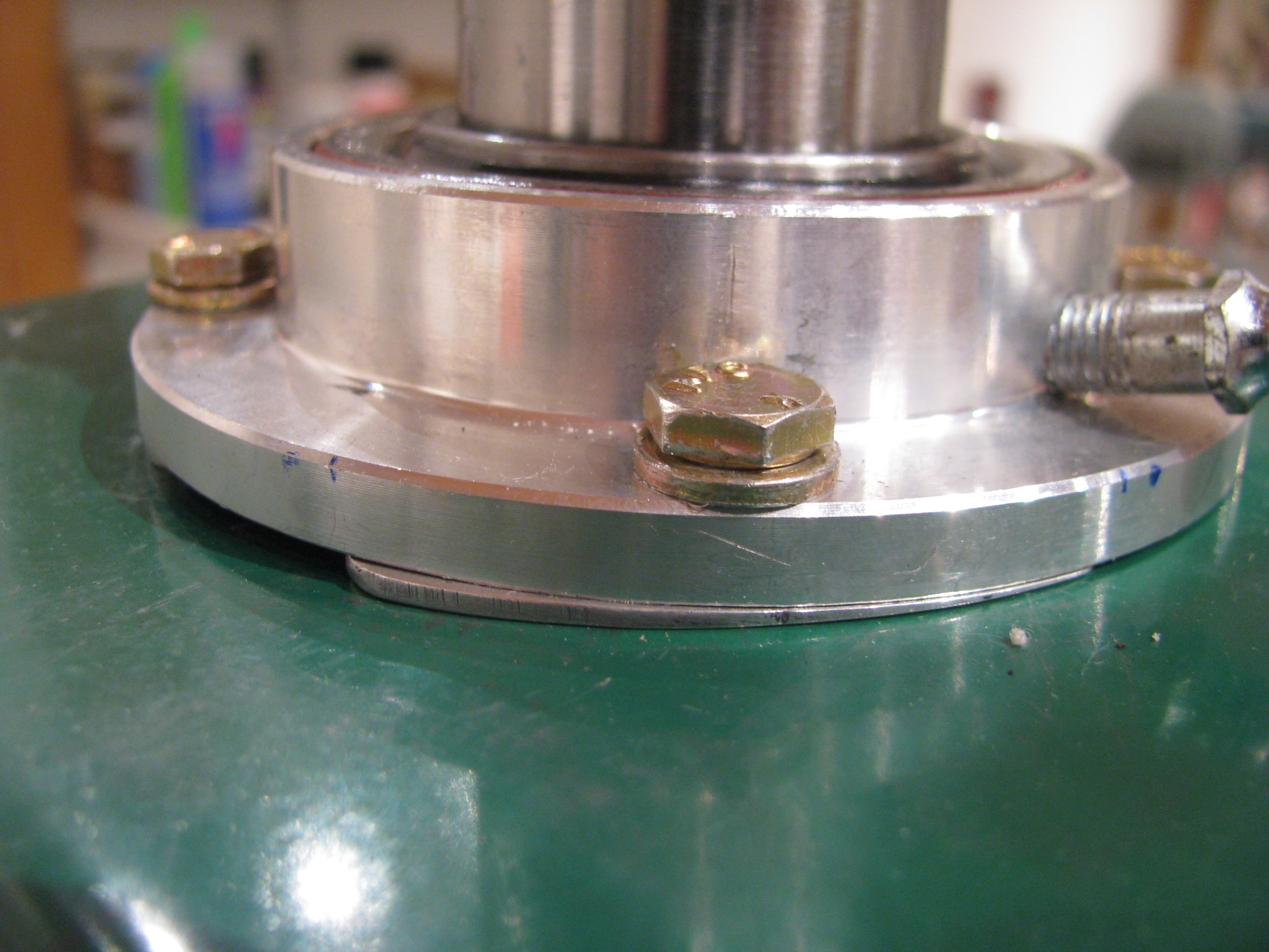
Drilling Transmission
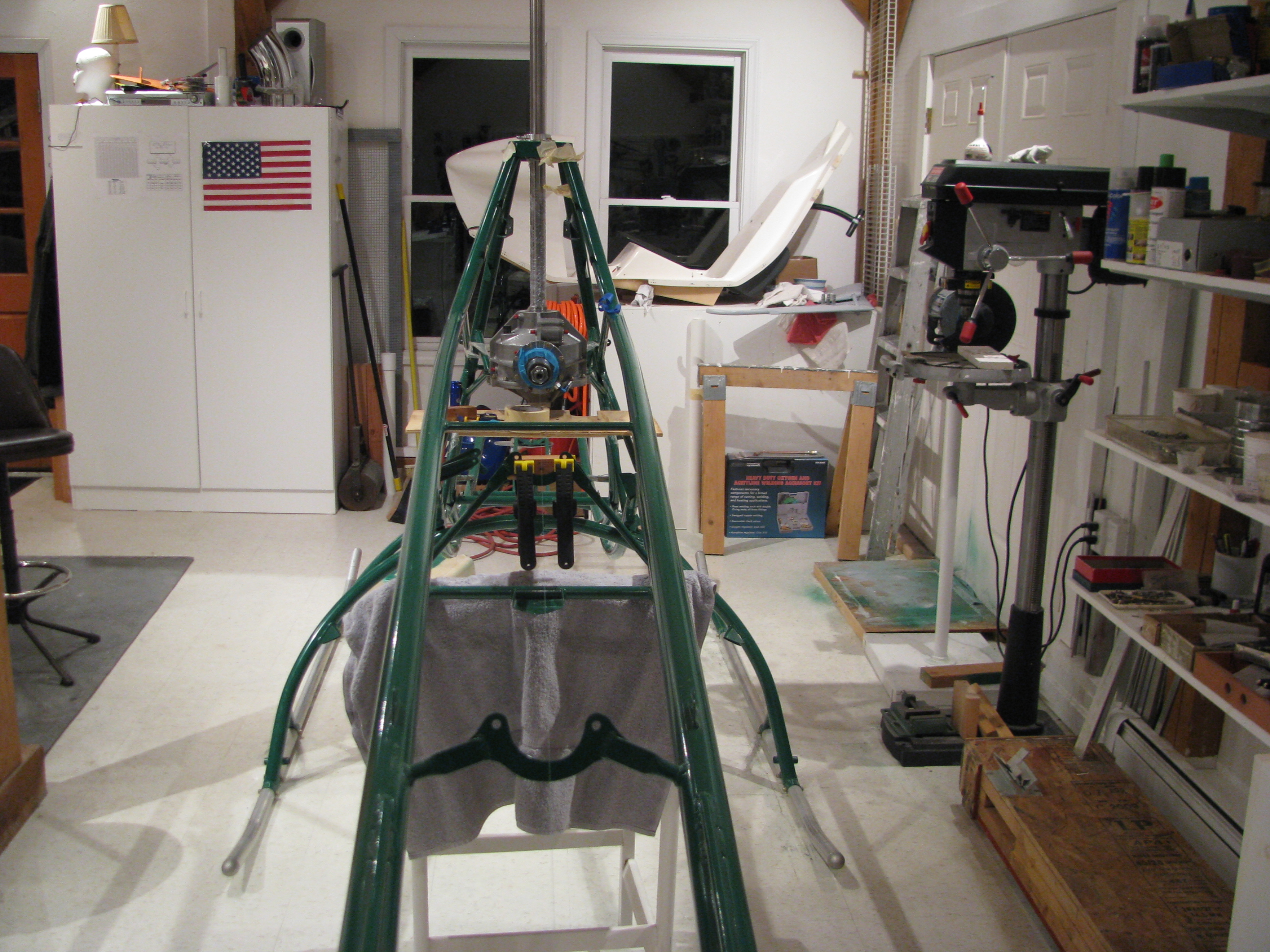
The holes are all reamed and there is no detectable slop at all, which I think is probably more important.
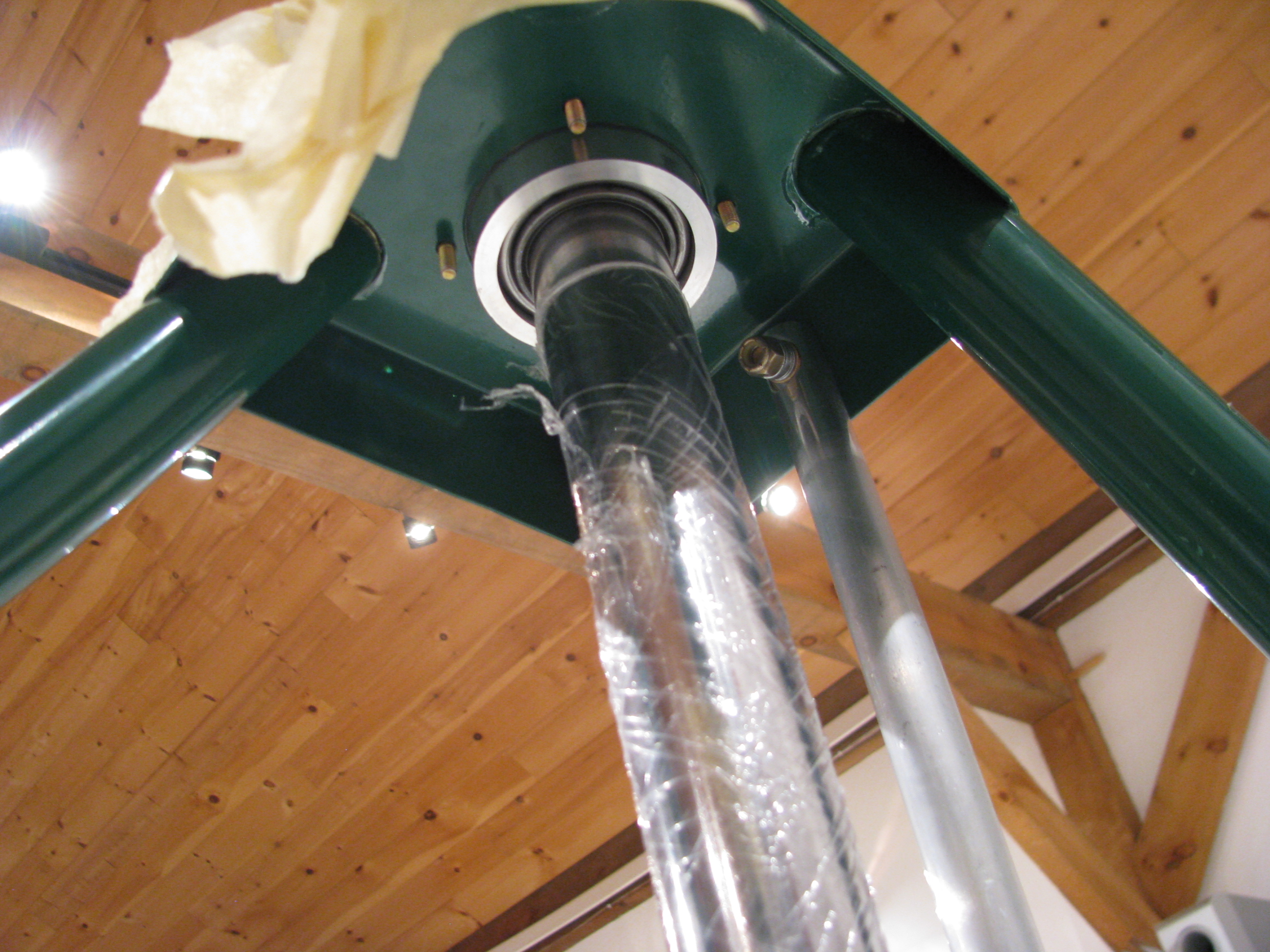
I am happy with how the hood bearing block slides cleanly down to the hood with absolutely no touching of the hood metal. This means there’s no preload or stress on the mast imparted by the frame mounting.
Transmission Alignment
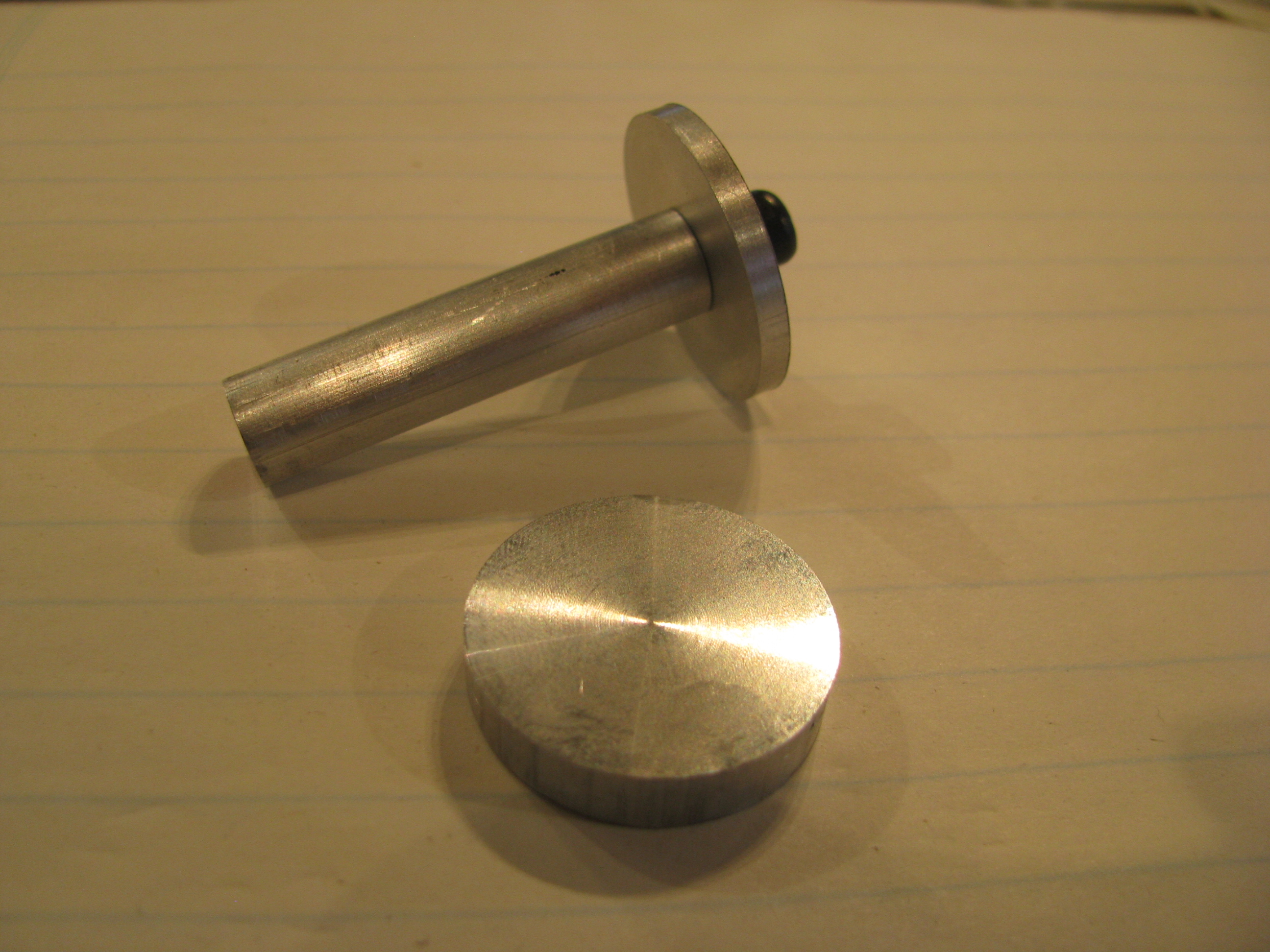
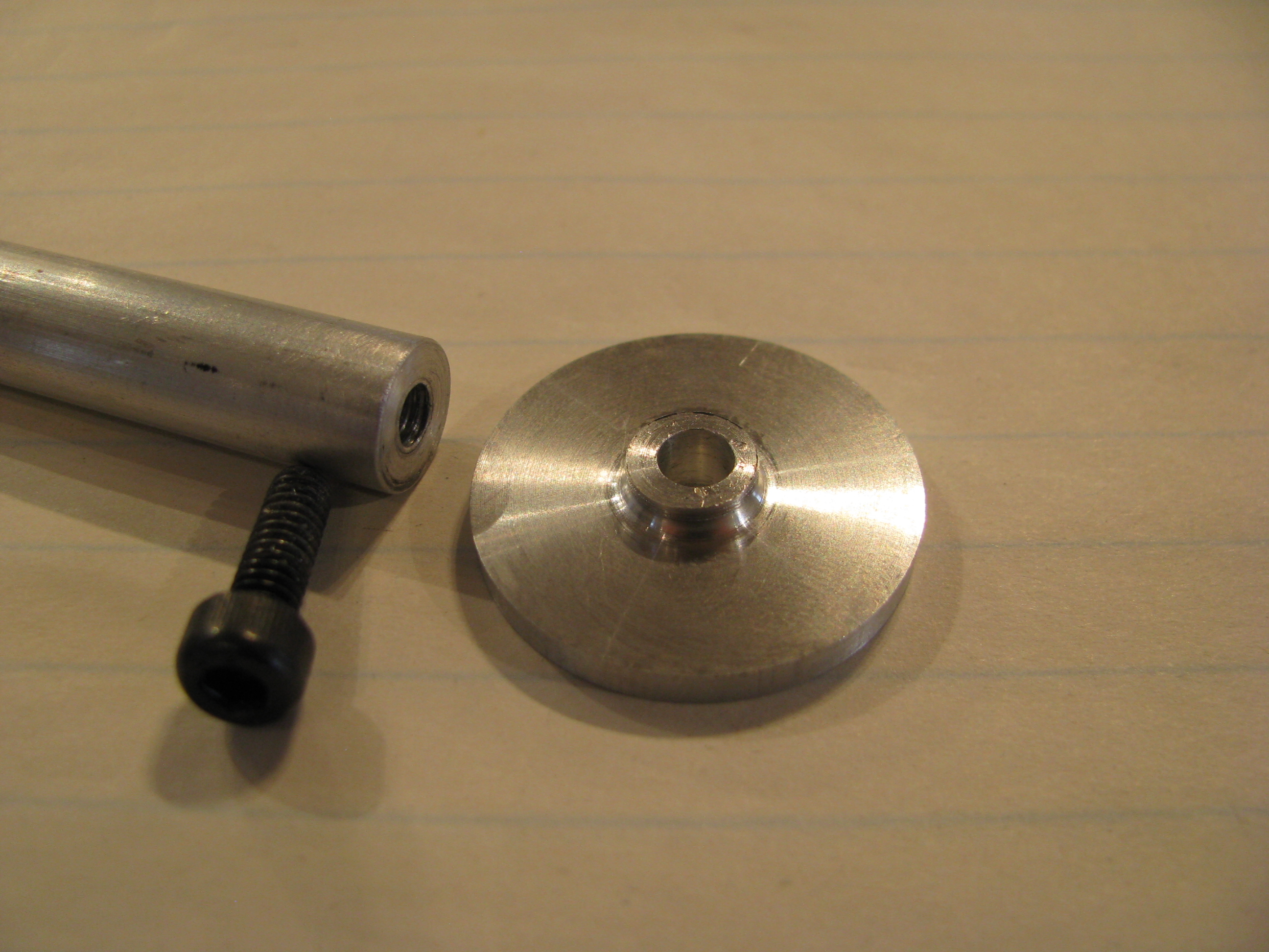
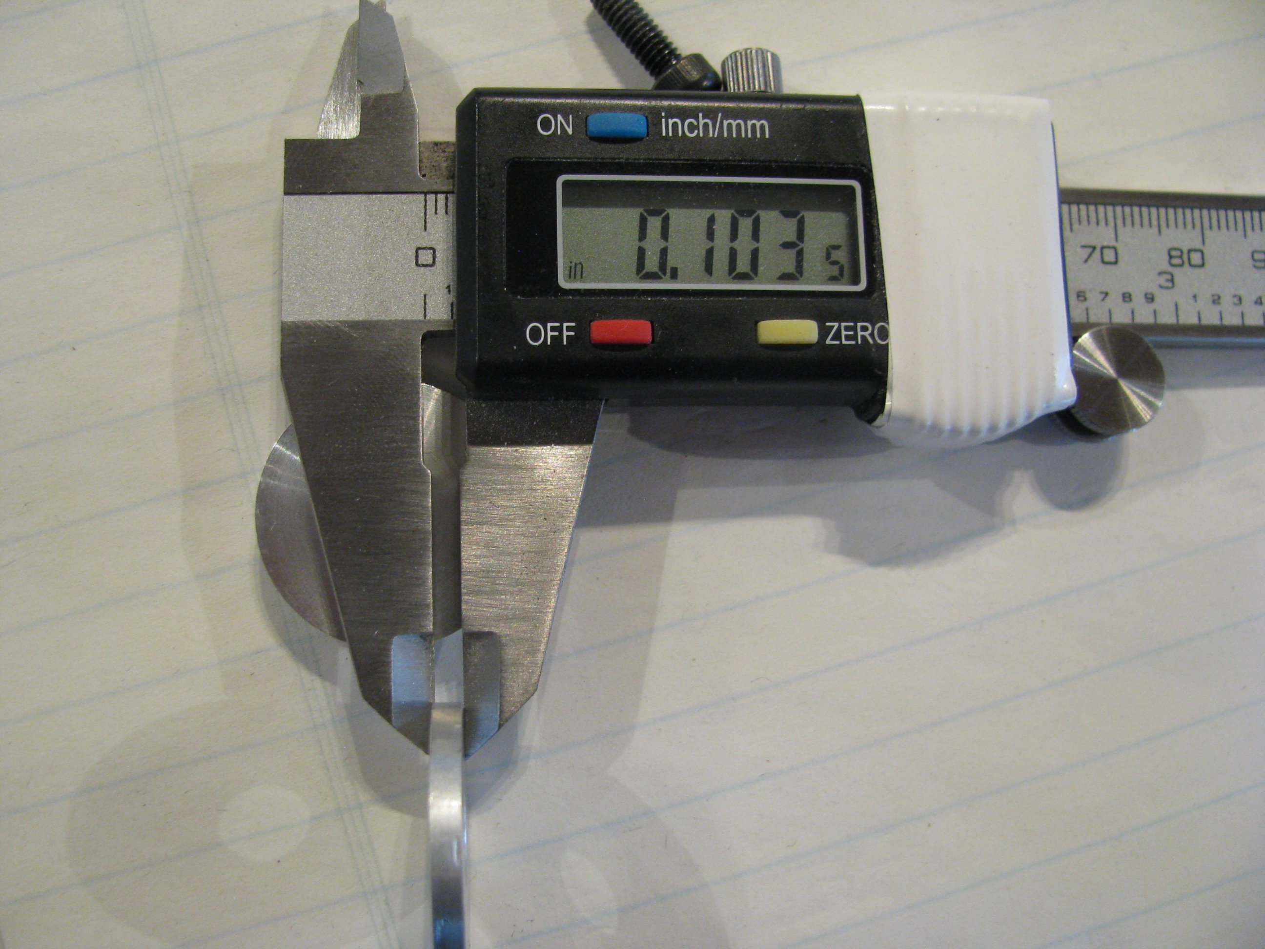
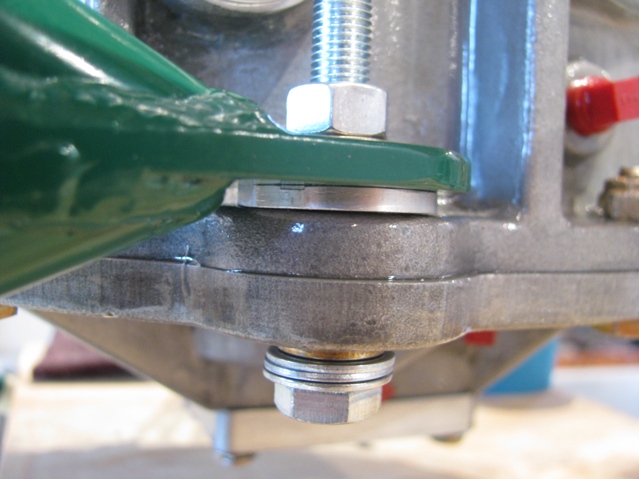
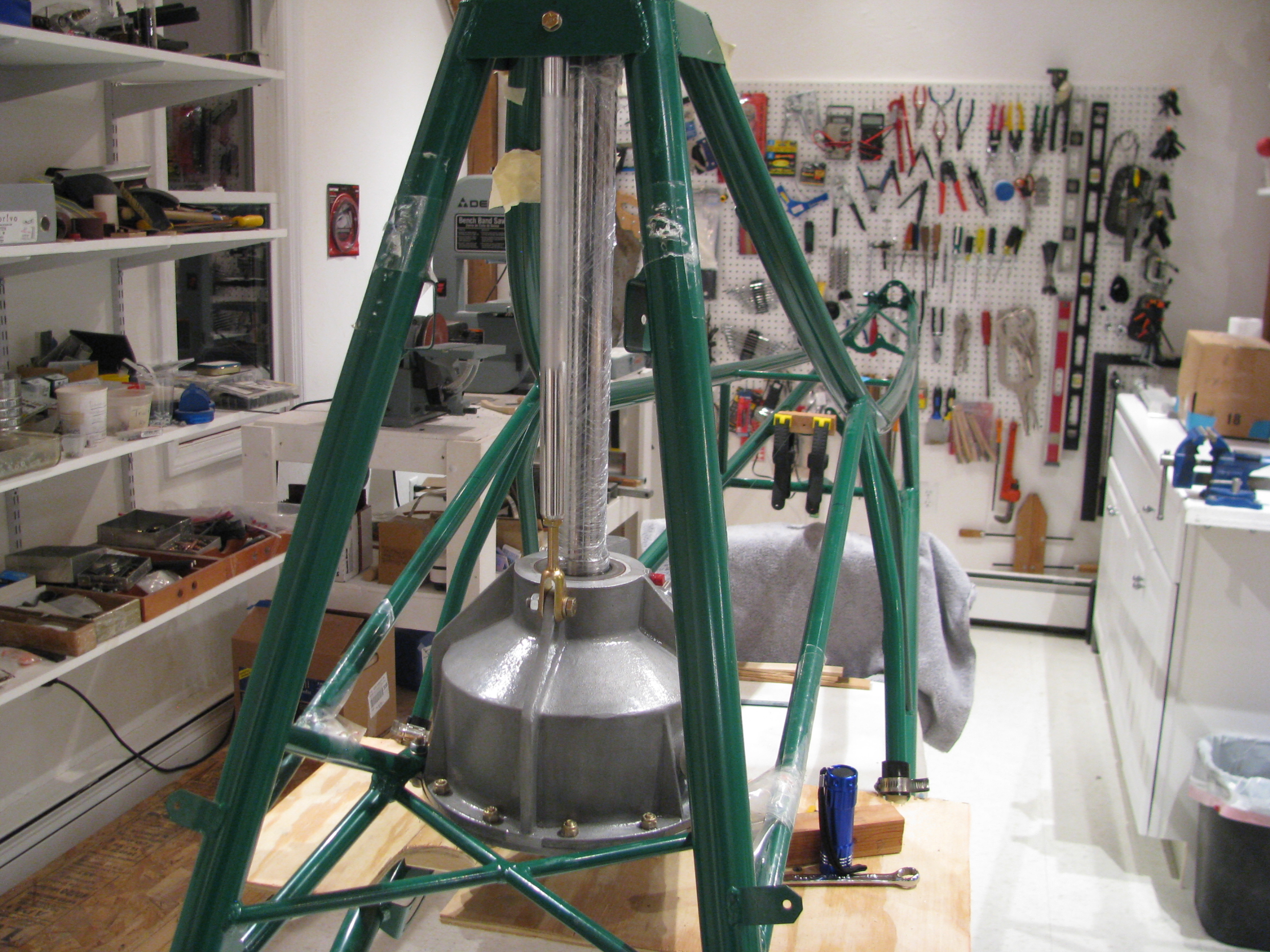
Initial Transmission Fit
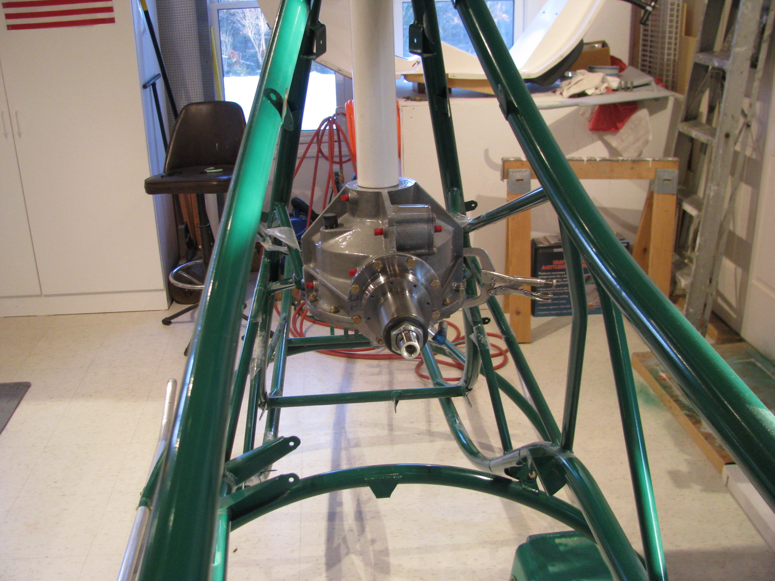
Hooray! Transmission preliminarily in place. That’s a piece of 2” PVC pipe, which fits perfectly to protect the shaft while sliding into position. This is definitely a 2 person operation.
Once in place I clamped a piece of wood underneath the transmission so I can lower it a few inches to clear the tabs when needed.
Ran the alignment string and rough set the pre-load offset angle (very precise twist/measure/clamp/repeat).
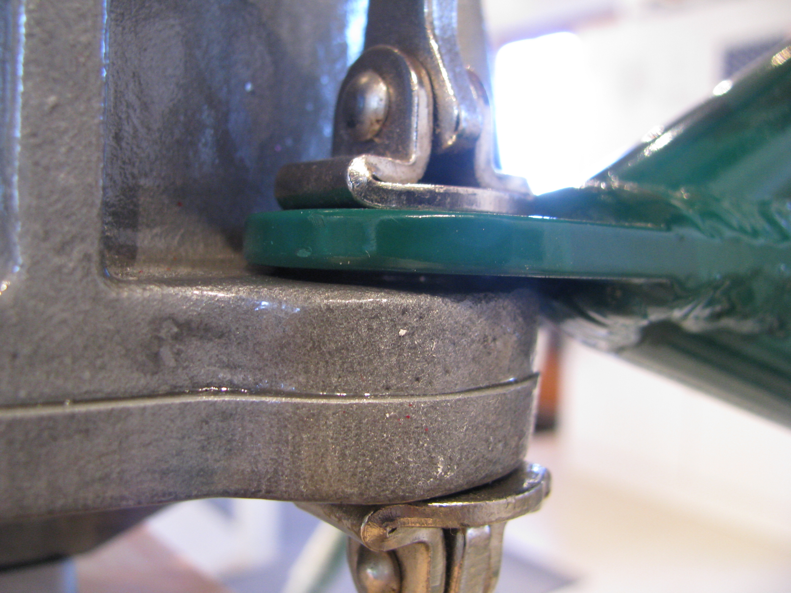
The undrilled side tab was not exactly parallel, so it had to be bent down about 0.75degree.
When the pre-drilled bolt was snugged, the first to bottom was the undrilled side. It also looks like the inner side of the tab touches first. I could either make an angled shim or perhaps take a touch of aluminum off the casting. I don’t want to stress the tab welds by trying to impart a twist in the steel tab.
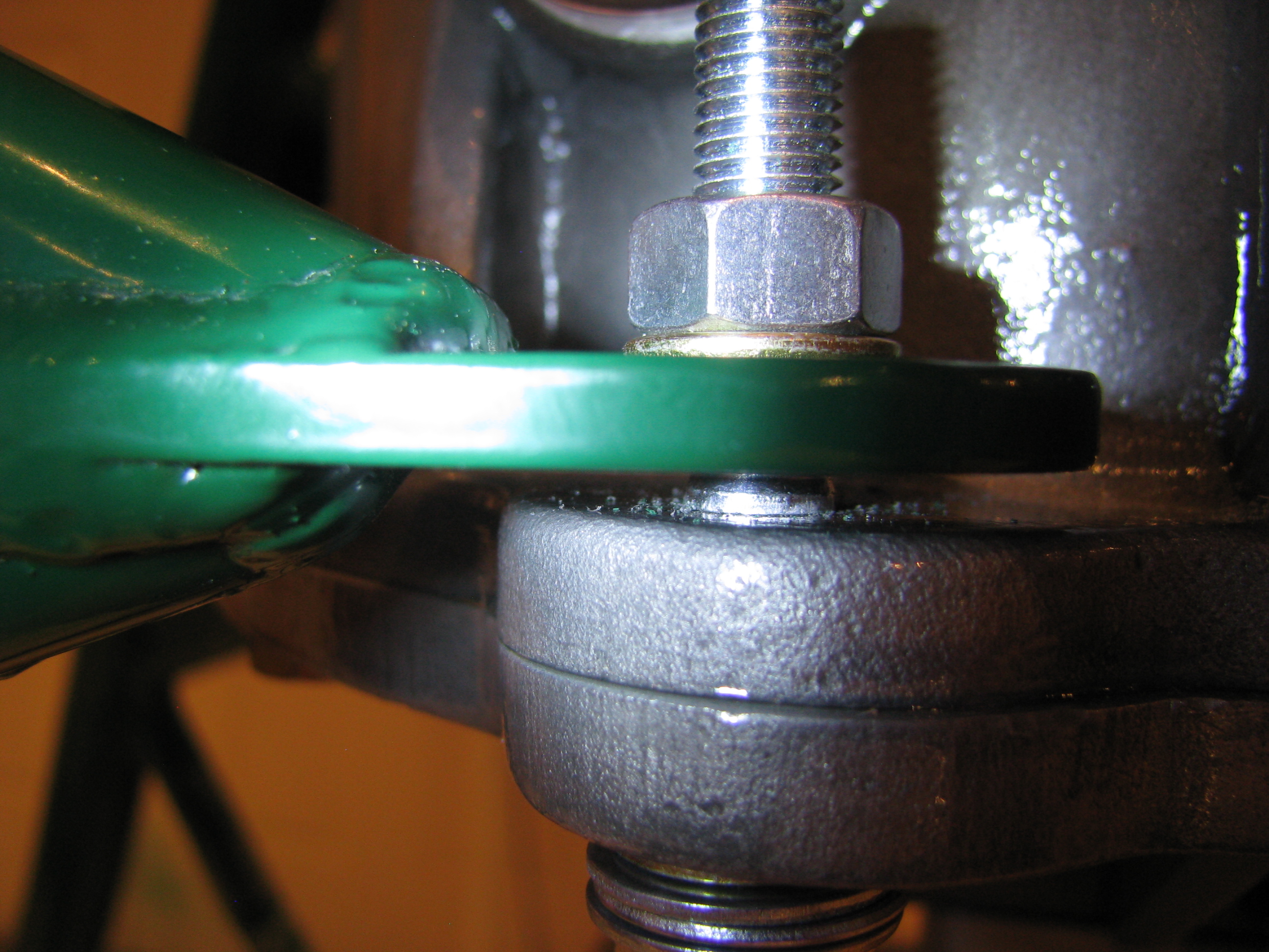
With the undrilled (right) side bottomed there’s a 63 mil gap between the left-side side tab and the casting. The photo also makes it look like they are not parallel. I’ll double check to make sure this is not a trick of the camera lens.
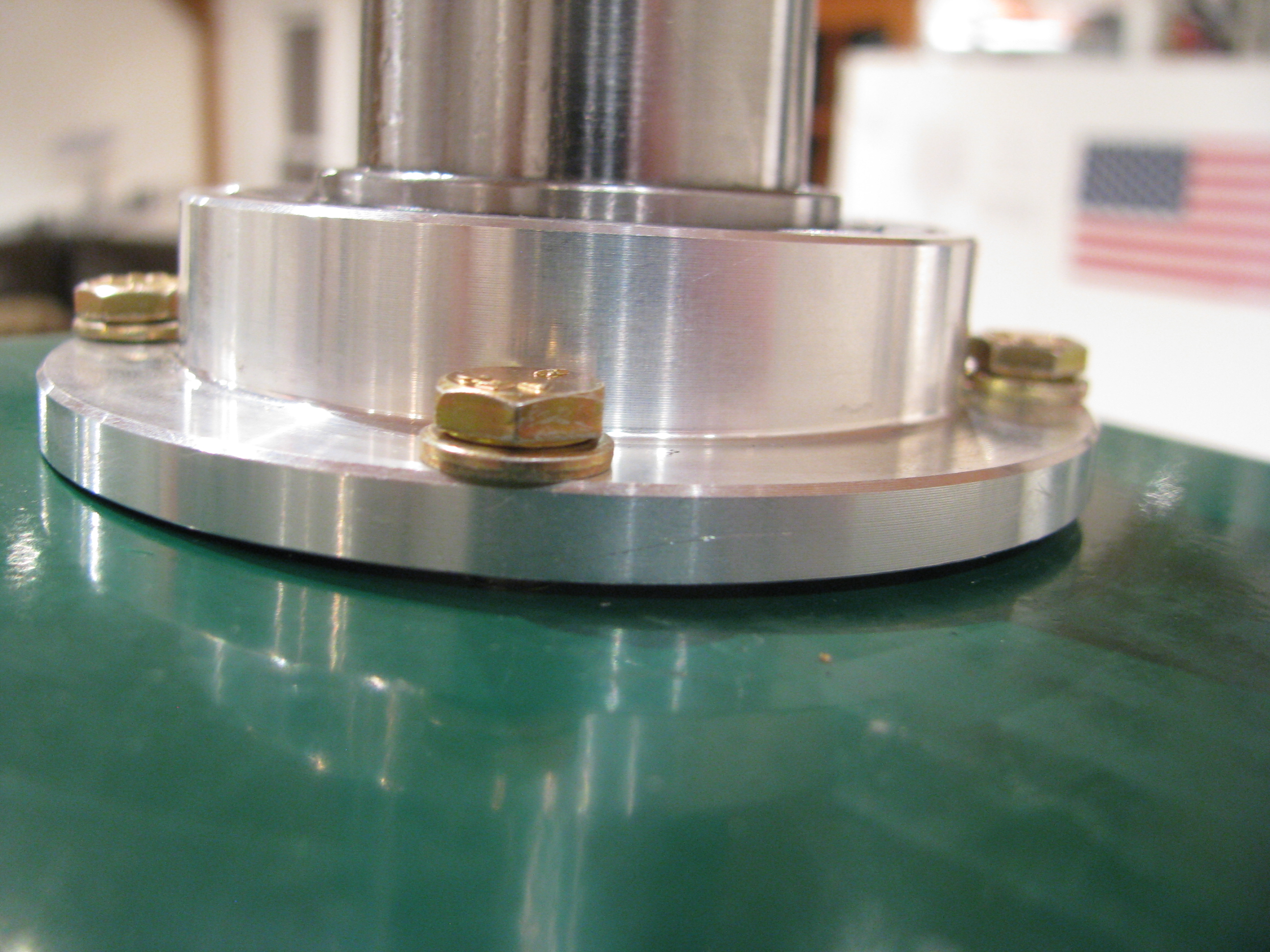
With everything jigged and clamped you can see the uneven gap at the hood bearing. It’s maybe 0.040” at its largest which is exactly on the right side of the ship. I think much of this is probably due to the built-in slight leftward tilt of the mast. I’ll work the main mounts before worrying to much about this.
I can judge the left/right tilt of the main mounts by making sure this bearing housing slides up and down easily when the main mounts are in position and clamped. I guess the fore-aft tilt of the main transmission is locked in place by the lift strut. I’ll have to play with that a bit. I will probably diddle around with this for a few hours to make sure every angle and clearance is understood and addressed before making permanent changes (ie: drilling that undrilled tab and the lift strut mount). Mistakes here would be difficult to fix and very expensive.
Transmission Prep
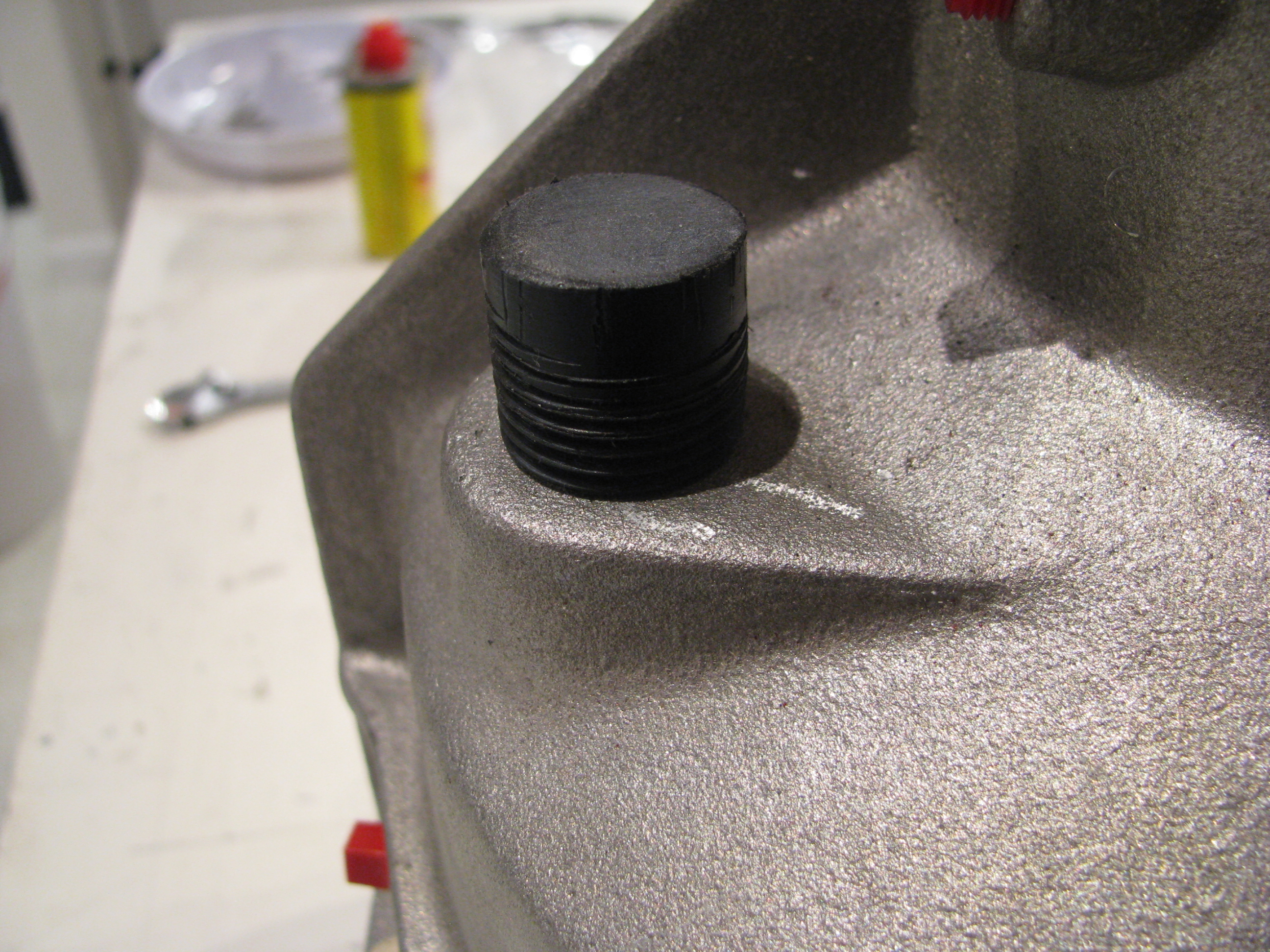
Here is why my progress slows to a crawl sometimes. BJ says to make a little wooden plug to cover the transmission fill during painting. Well, instead of wood, I turned this this little plastic block down on the lathe and then threaded it to 1/2” NPT pipe thread. I messed up the threads and had to make a new one. Of course cutting plastic on the lathe is very messy, so I had to clean up the shop afterwards. All told about an hour and a half to make a stupid little plug.
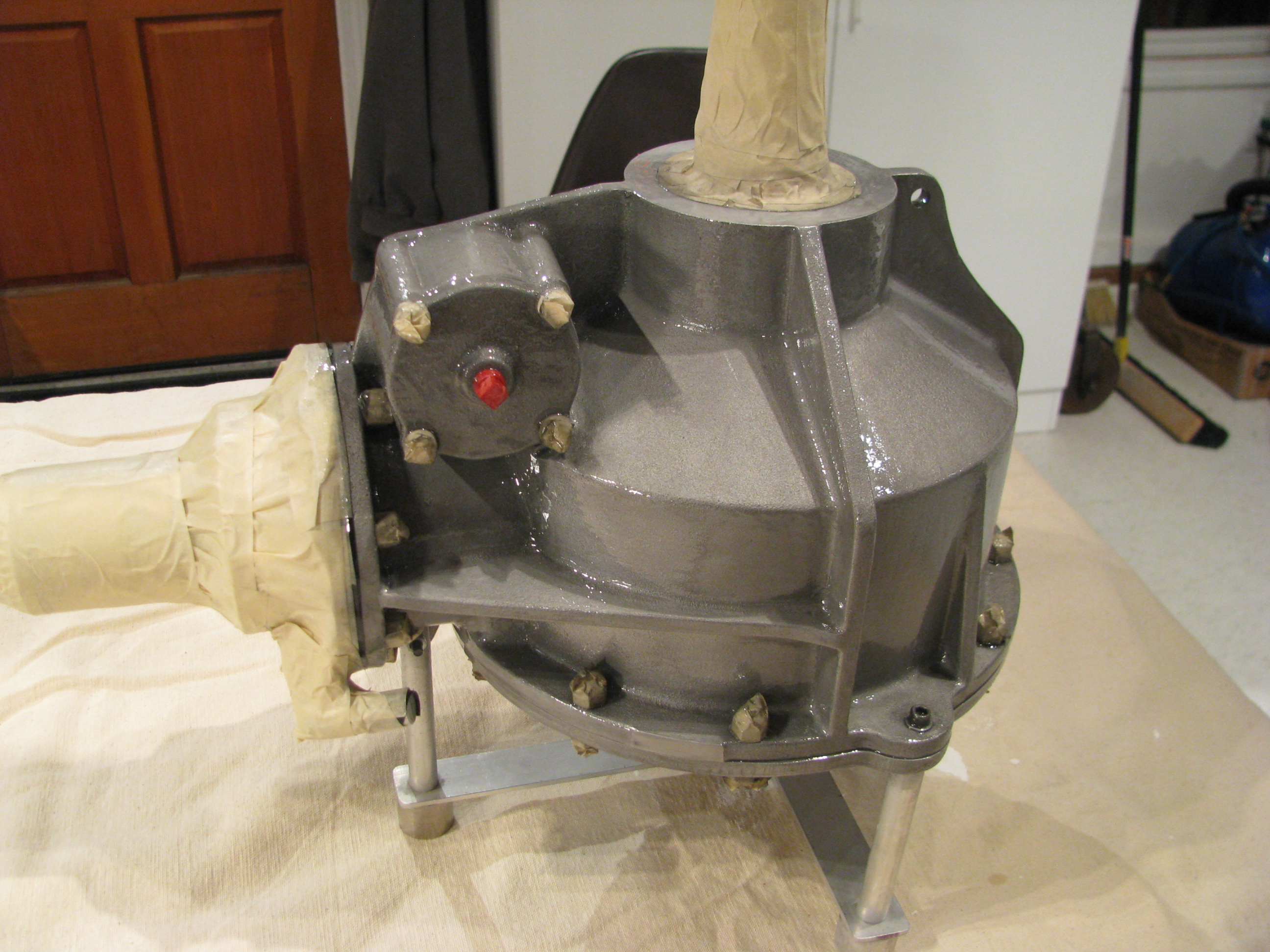
Sandblasted with 80grit followed by 220, then wirebrushed with stainless steel and then a brass brush. It looked fantastic before the painting, but of course that wouldn’t have lasted. Two coats of POR-15 clear. One light to “seal” the casting, then one medium-heavy to level it out all with a brush. It looks candy-coated now.
It took almost a full week of curing before it stopped feeling tacky.
TR Gearbox Prep
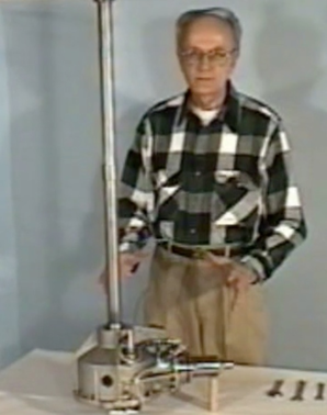
OK. Time for the serious stuff; Mounting the main transmission, tail rotor shaft and tail rotor gearbox. Once the main transmission is mounted, the tail rotor shaft can be fabricated and aligned. That’ll go a really long way to making the whole thing start to look like a helicopter. To date the bits go on, then they come off, so anytime my kids stop by the shop it looks like I am back a square one.
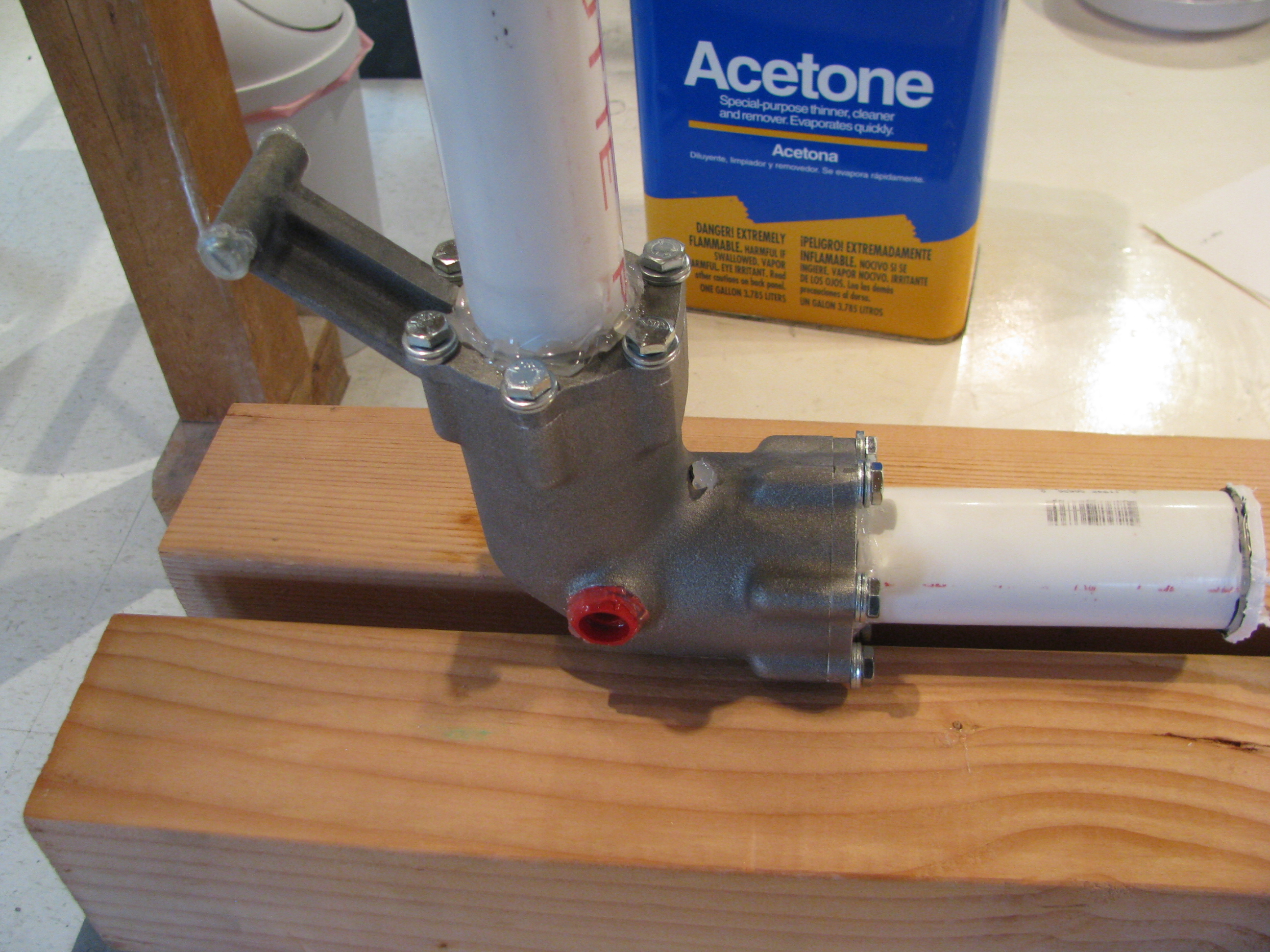
Baby Steps: I masked off the important bits of the rail rotor gearbox. That’s just PVC with hot glue around the bearings. The the exterior got a sandblast with 220 grit glass, blown off, and rinsed with acetone.
Those are cheap HW store 1/4-28 bolts since they’ll get blasted too.
I ordered a gallon of the Allisyn ProGear21 75W-90W oil today. Holy crap! $60/gallon.
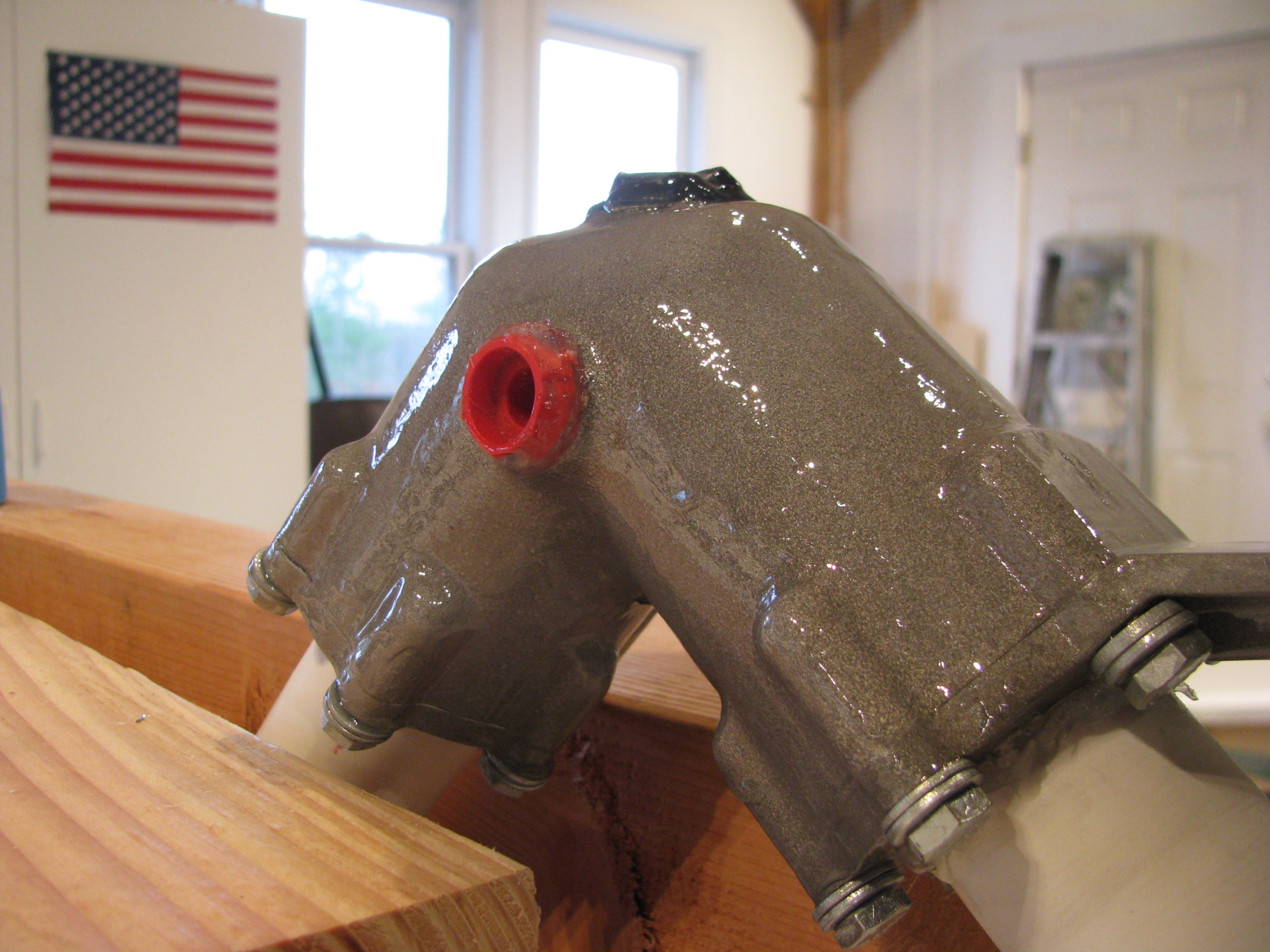
Wow. POR-15! Magic stuff. Two coats and this thing looks great. It’s like coating it with a form-fitting layer of glass. From reading the web I have to resist the strong temptation to touch it since it can take days to completely dry.
I wanted to try something small before committing to the main transmission with the POR-15. I have no reservations at this point. Some folks use color on these parts, but I like the effect of keeping the mechanical parts looking like manly hardware.
Important note on the POR-15: Don’t mix it in a plastic cup! The first little bit sat for a minute, then ate through the cup (polycarbonate, I think) and then ate through the coat of polyurethane on my workbench. Strong stuff. I had to steal a glass form the kitchen, then dig around for a camel hair brush instead of the little plastic one I was going to originally use.
I also ordered a transmission lift strut from Hap Miller today (nice guy!). I’ve heard good things about it from Juan R’s site and really don’t like the “heat and smash” tubes that are used in a number of places. I’ll probably use his tail fin braces as well.
Prior to painting the main transmission I took a series of photos so I would have a reference for where the various tubes and fittings go on reassembly.
GearboxPlumbing_1.jpg
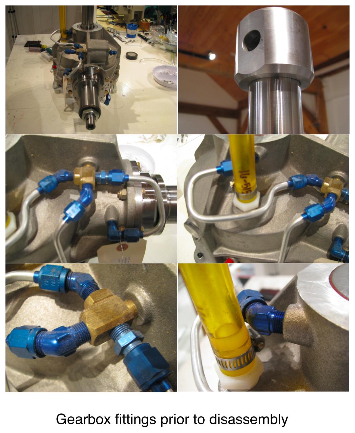
GearboxPlumbing_2.jpg
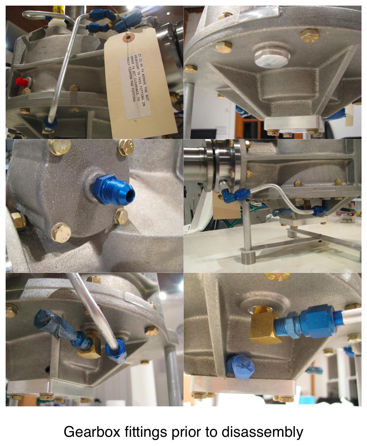
GearboxPlumbing_3.jpg
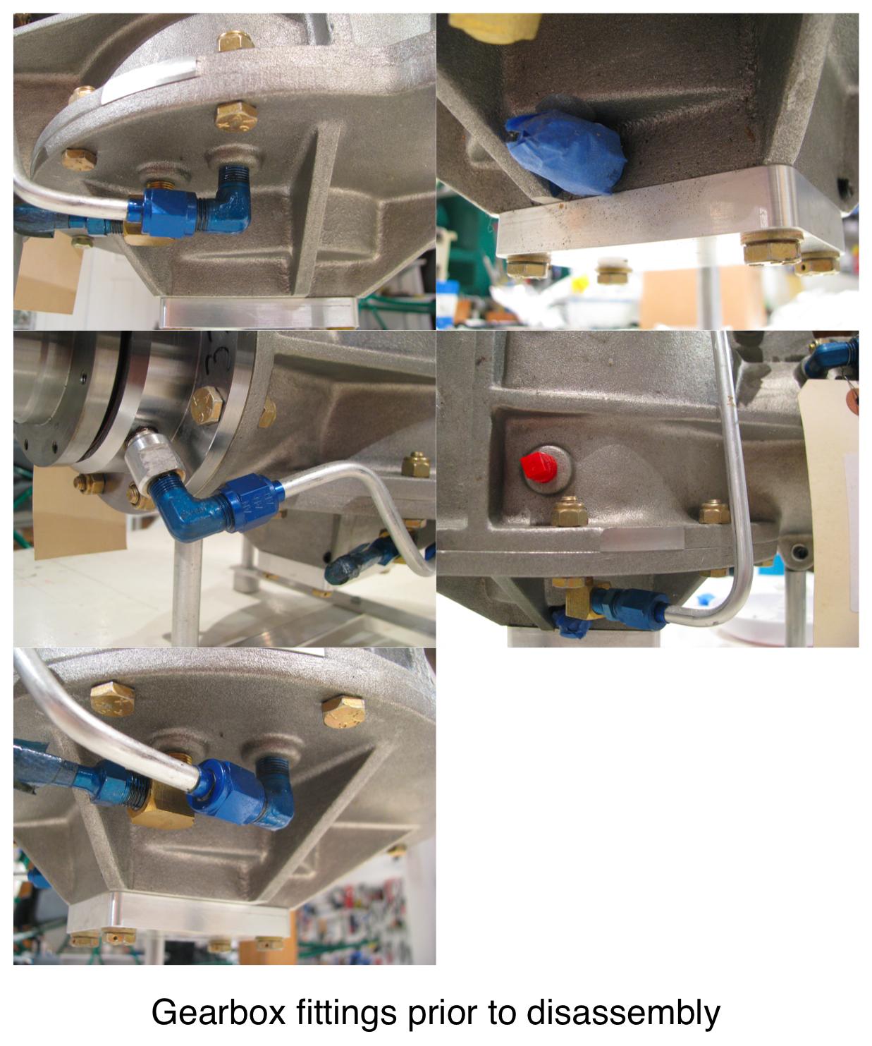
Aux Tank Mounting
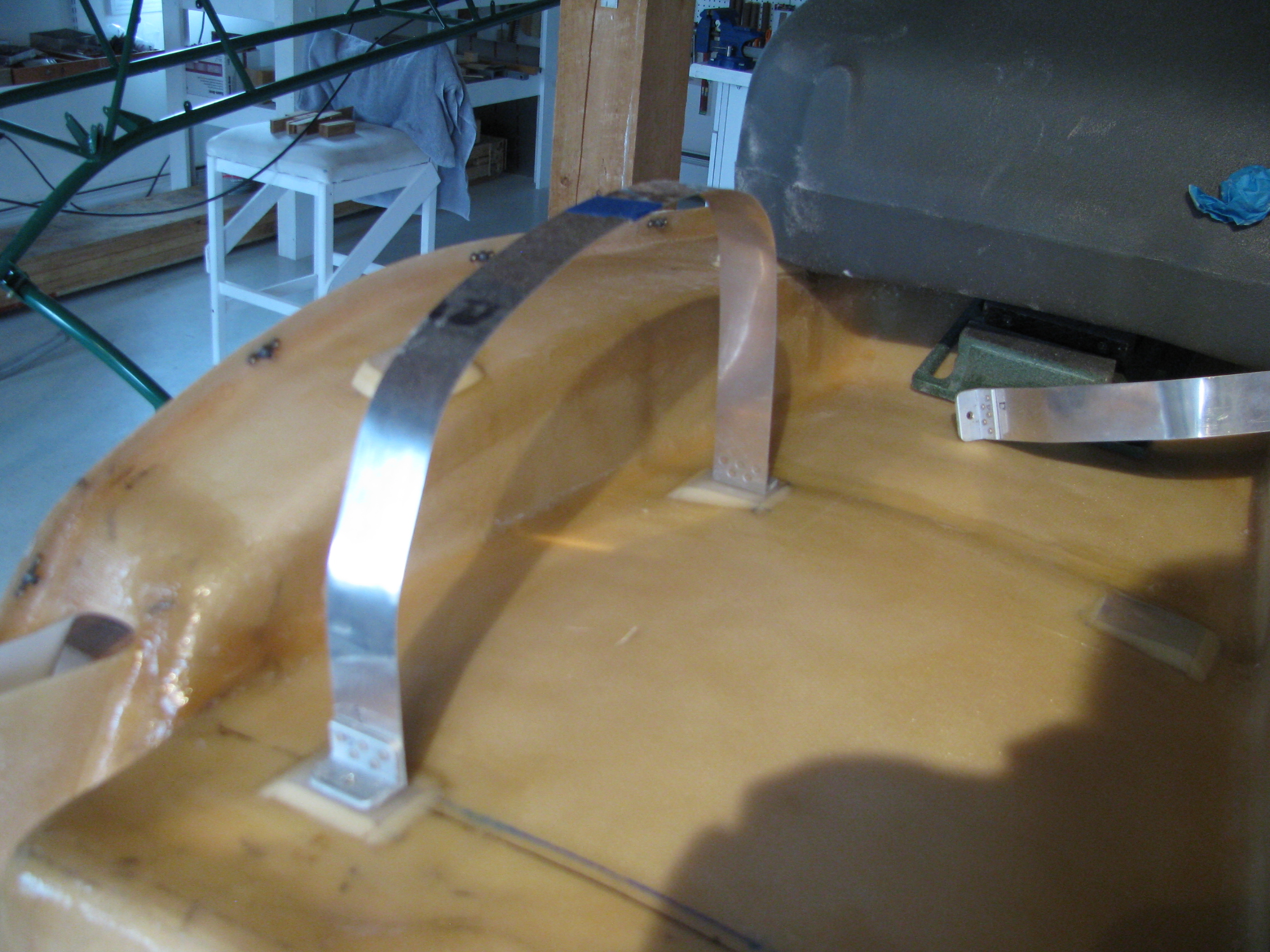
I set to work fabricating the hold-down straps for the aux tank. I didn’t like the way BJ called for the strap to be simply bent and bolted to the back of the seat. Seemed like there would be a stress point right at the bolt, so I riveted on a couple of pieces of angle to better handle the 90 degree force turn.
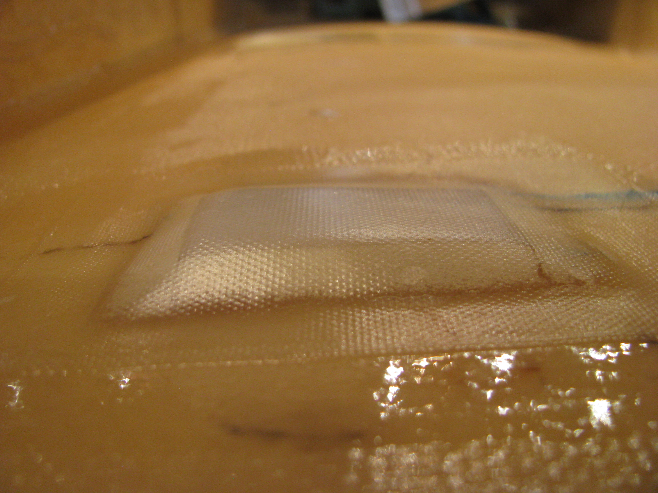
The curve of the seatback also caused the straps to not sit flat, so I glued on some foam strips, poured in some flox, ground and sanded them flat and perpendicular, then glassed over the foam.
The close up shows a tiny little void in the glass in the lower right, but this is non structural, so we won’t panic. I am learning fiberglass and my results are getting better, but I won’t be building a Long-EZ yet.
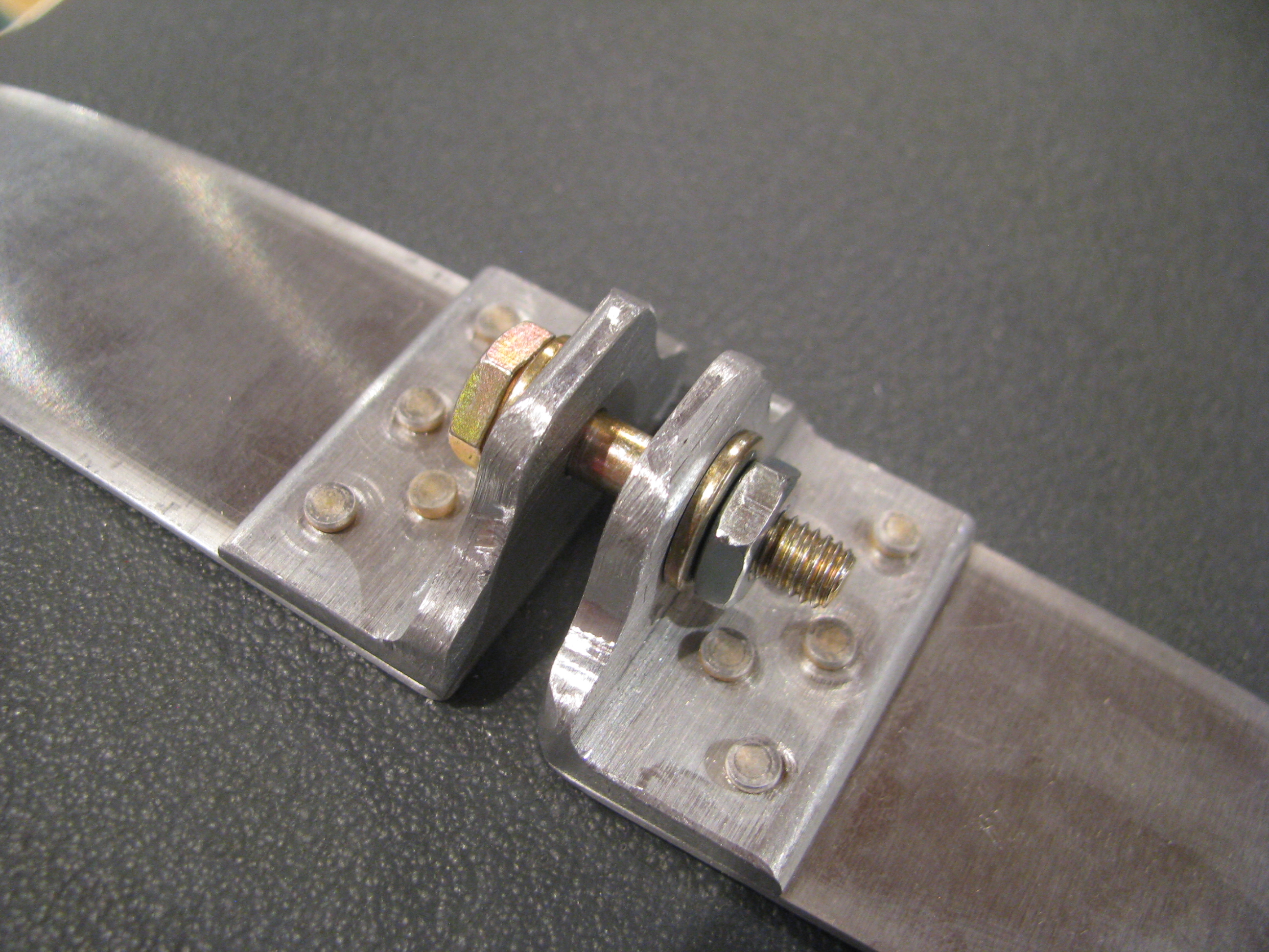
I whipped up these little brackets to allow for snugging down the straps and taking up any excess slack in the straps themselves. Not much weight and it should be easier to make sure we’re tight and not moving around at all.
Using BJs method would be lighter, but you’d have to have the strap length absolutely perfect to have them reach the correct tension right as they bottom out. Probably not possible with the flexing of the tank.
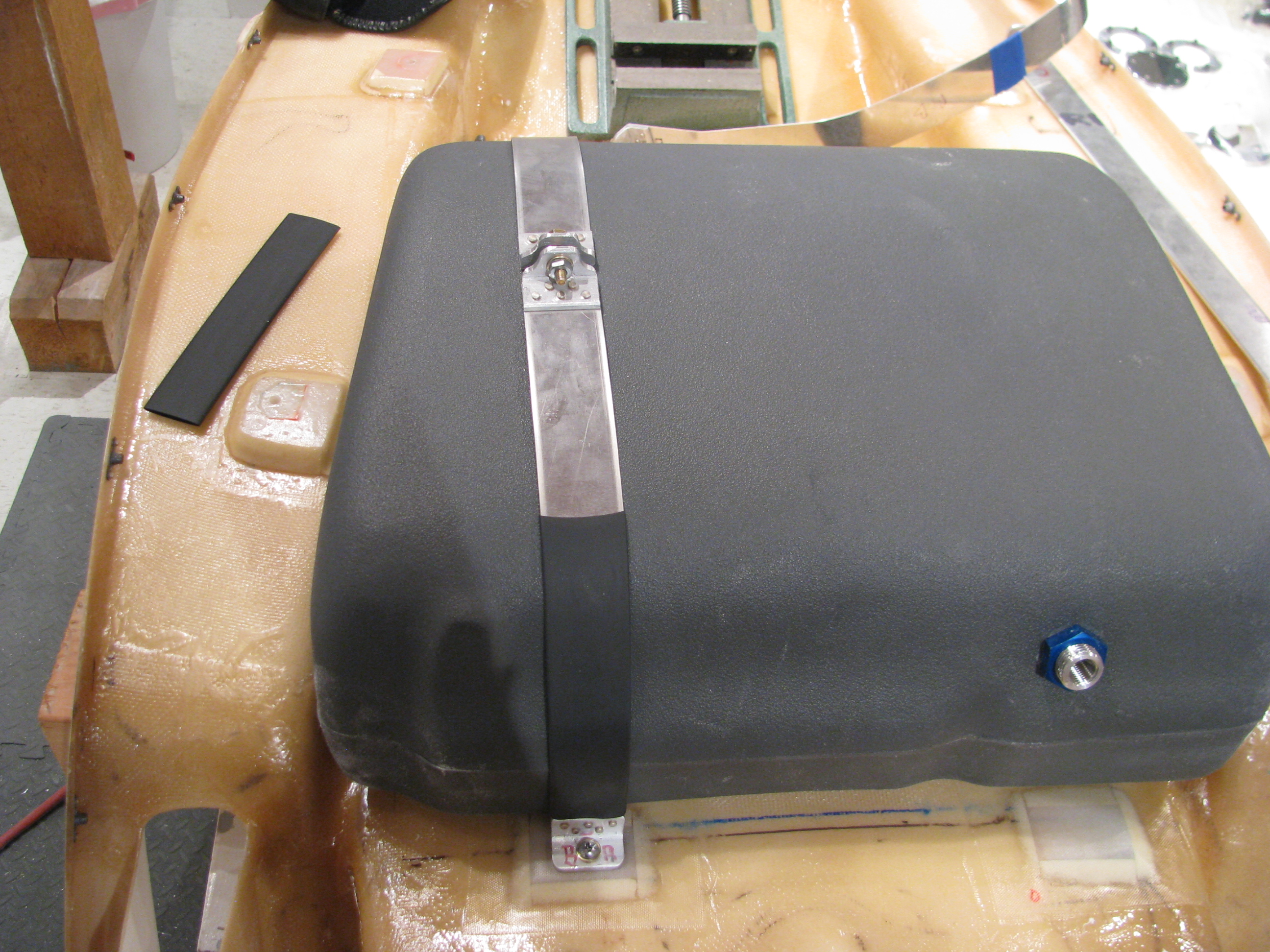
One down. One to go. I need more of this jumbo shrink tubing and to paint them up on completion.
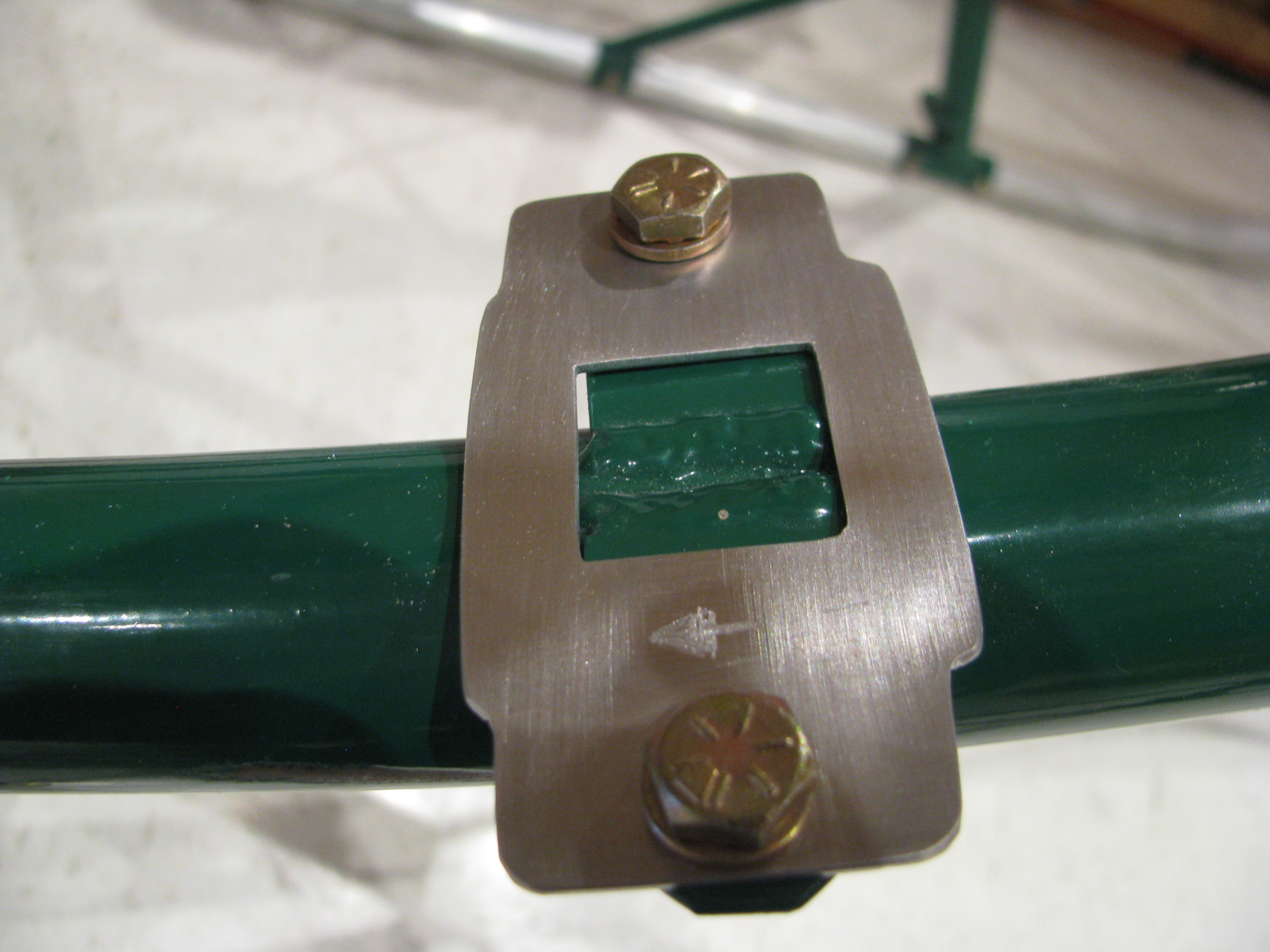
12/31/11 This is the fuel pump mount pad. The welds that mount the tabs to the frame extend up a little. Instead of grinding them down (weakening the joint and breaking the powdercoat) I just made this 0.050 shim in the shape fo the fuel pump base. It’s as thick as the welds and everything sits flat now.
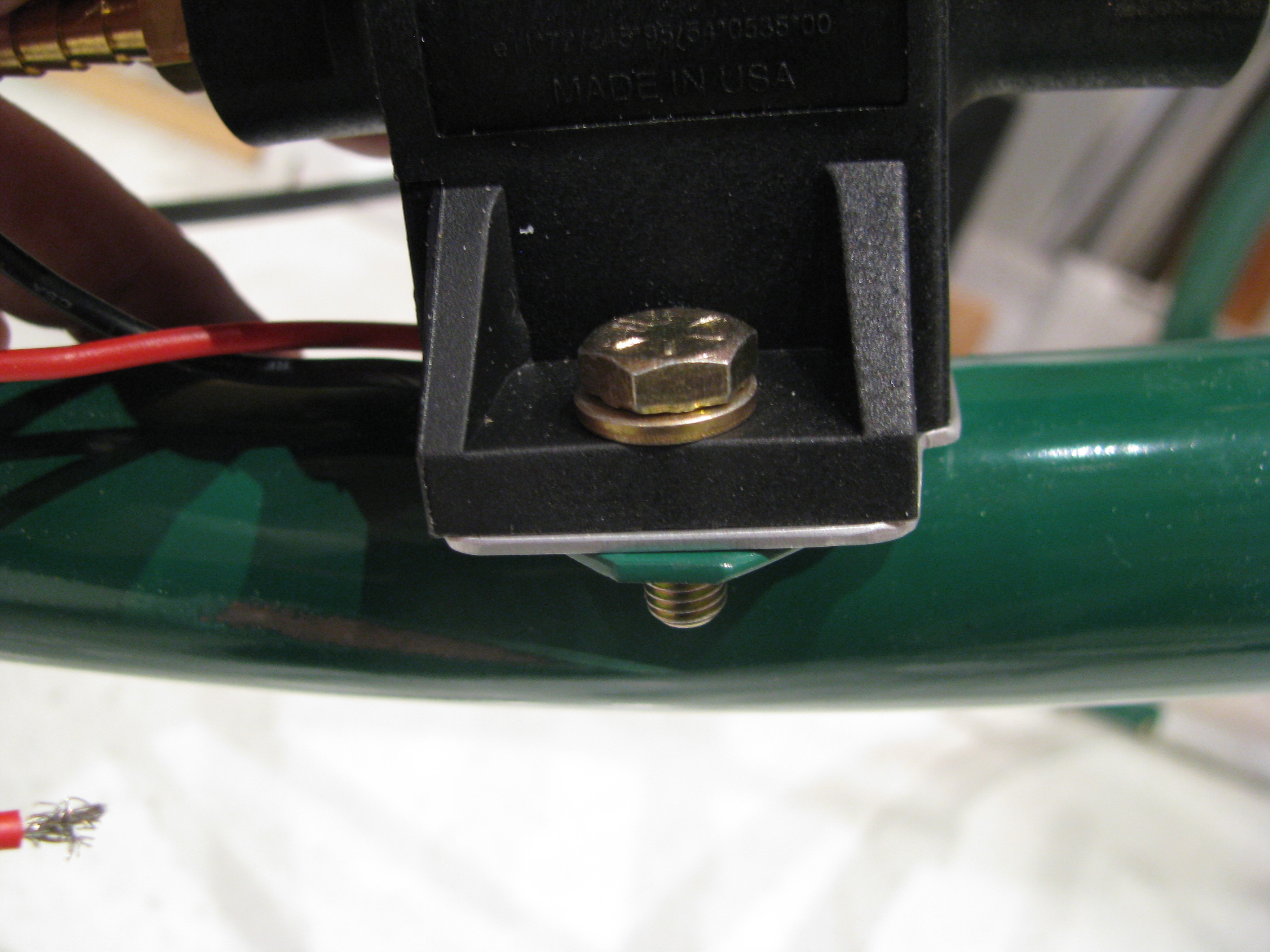
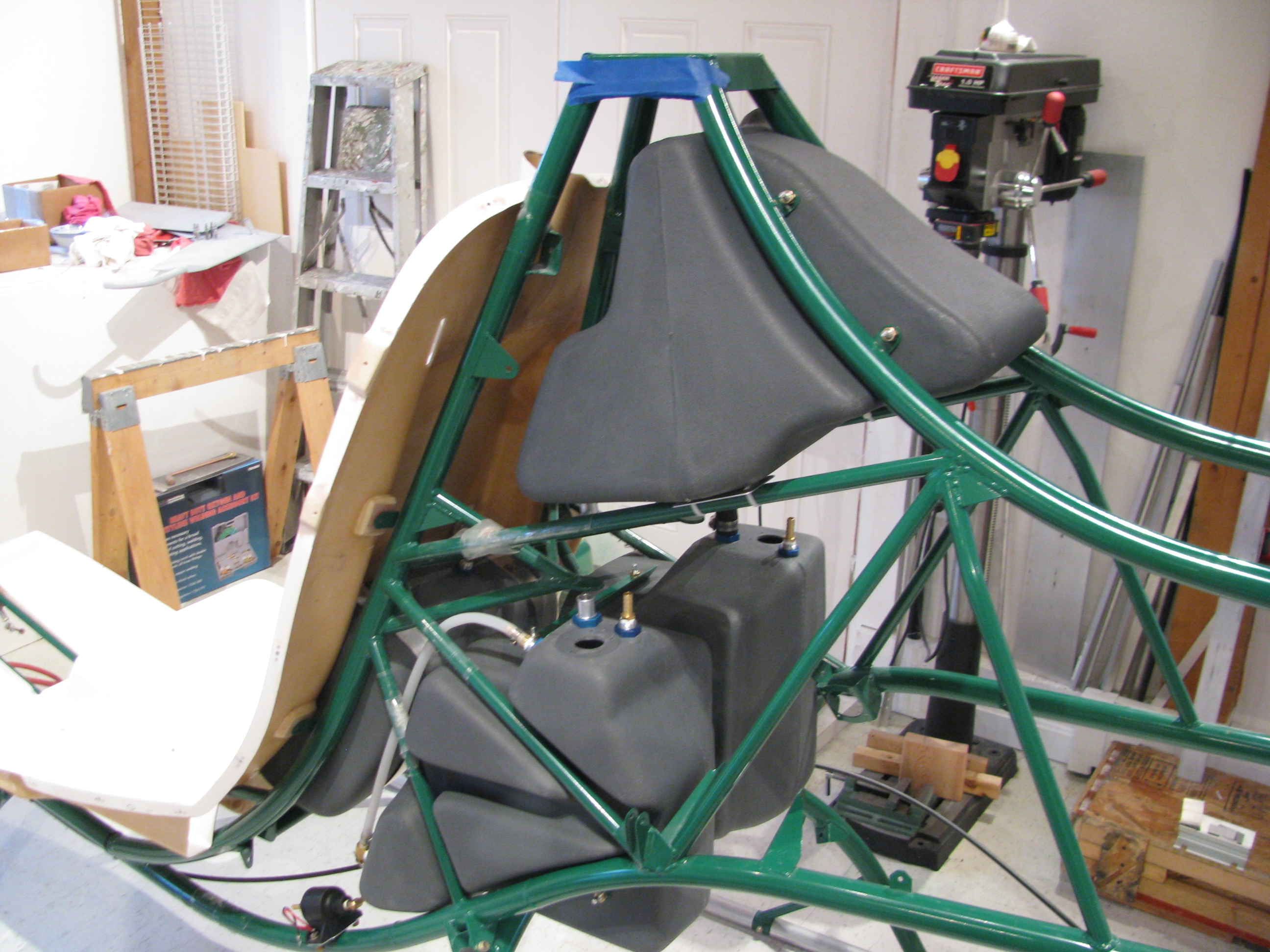
Done for now. The tanks have been preliminarily fit, the hoses have been cut, and everything looks good. I have a fuel flow gauge and sender on order. When they get here I will seal it all up and do a leak check and be done with fuel until final assembly.
One note: I did elect to forego the Westberg sender and gauge since it seemed like a pretty expensive way to only measure the lower tank. I saw a video on the web of one builder who ran a sight gauge in the cockpit along the back interior edge of the seat pan. Pretty primitive, but an effective way to see the real level from the top to the bottom. I am thinking this is the way I’ll go as a gauge of last resort. The fuel flow meter will be primary with the visual sight level as backup.
Detail Fuel System Work
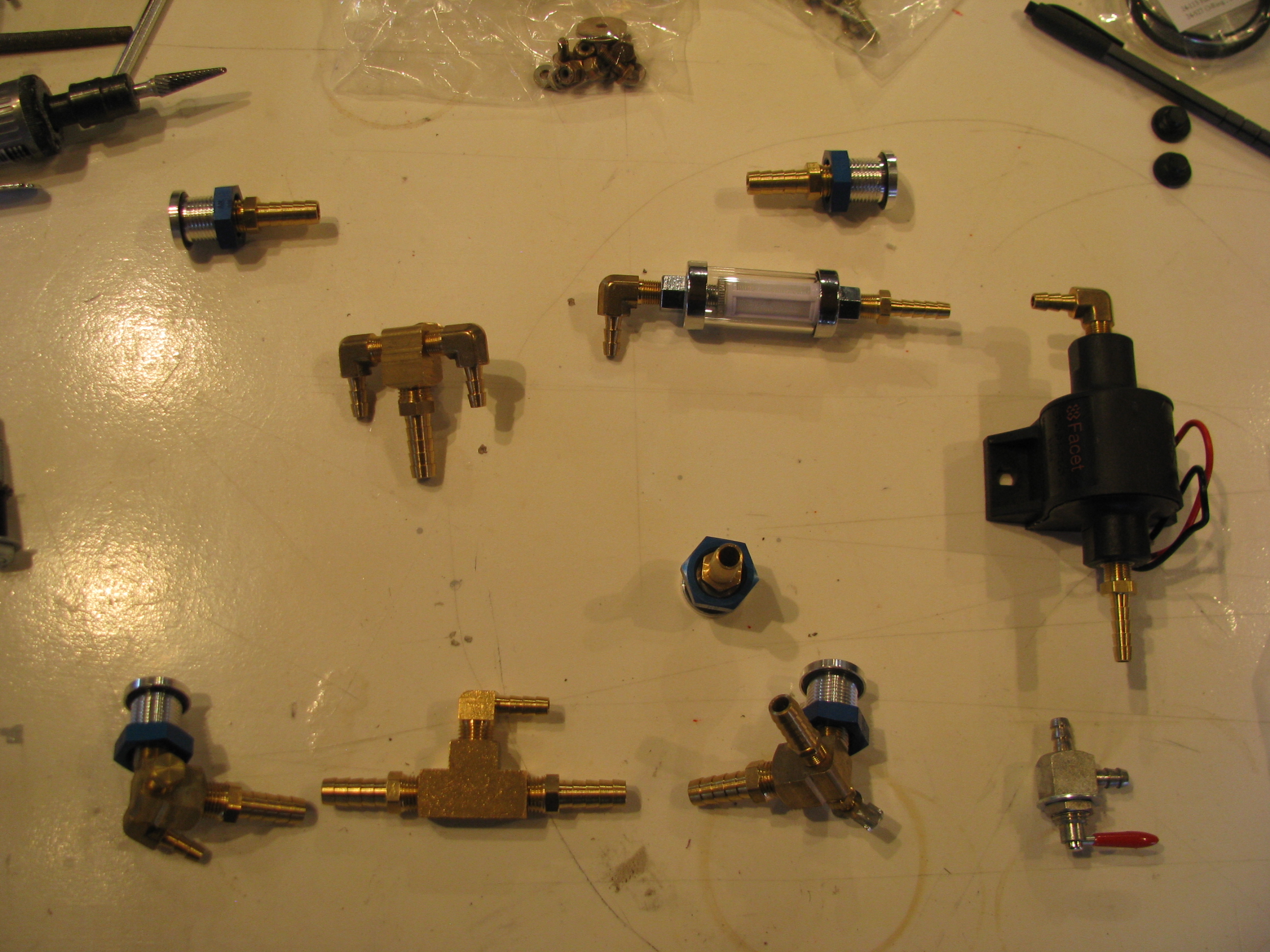
There are a lot of bits and pieces in many, many bags. I will admit that I did not inventory the fuel system when I took delivery of the kit, but everything seems to be there. So far the only thing I have been missing in the entire kit thus far has been one thin washer back in the mixer assembly.
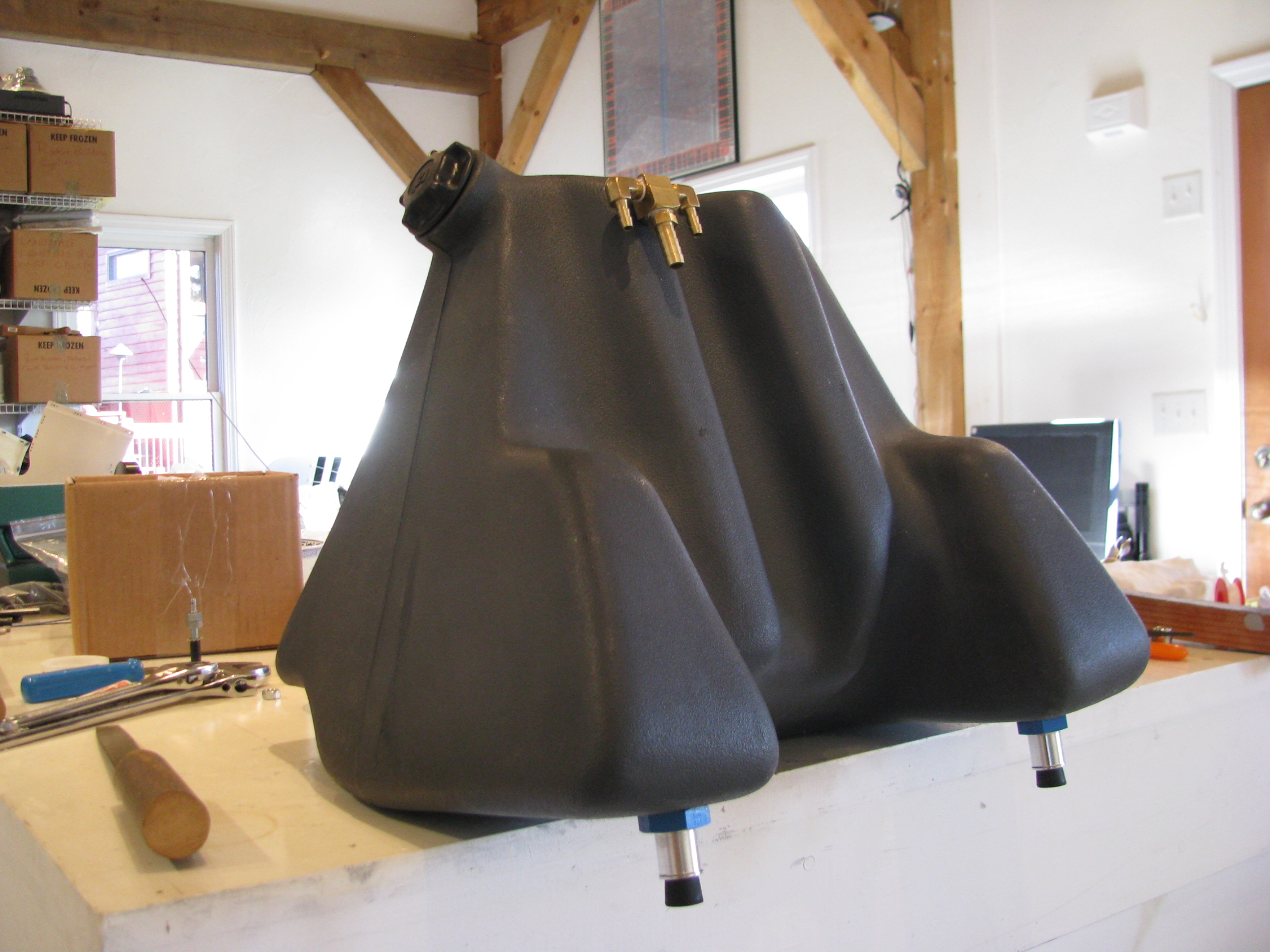
The top tank is fitted out and drilled. I corked and checked for leaks with water. I plan on pre-assembling the entire fuel system in the ship and leak testing it in its entirety, then remove it all and then setting it aside until final assembly.
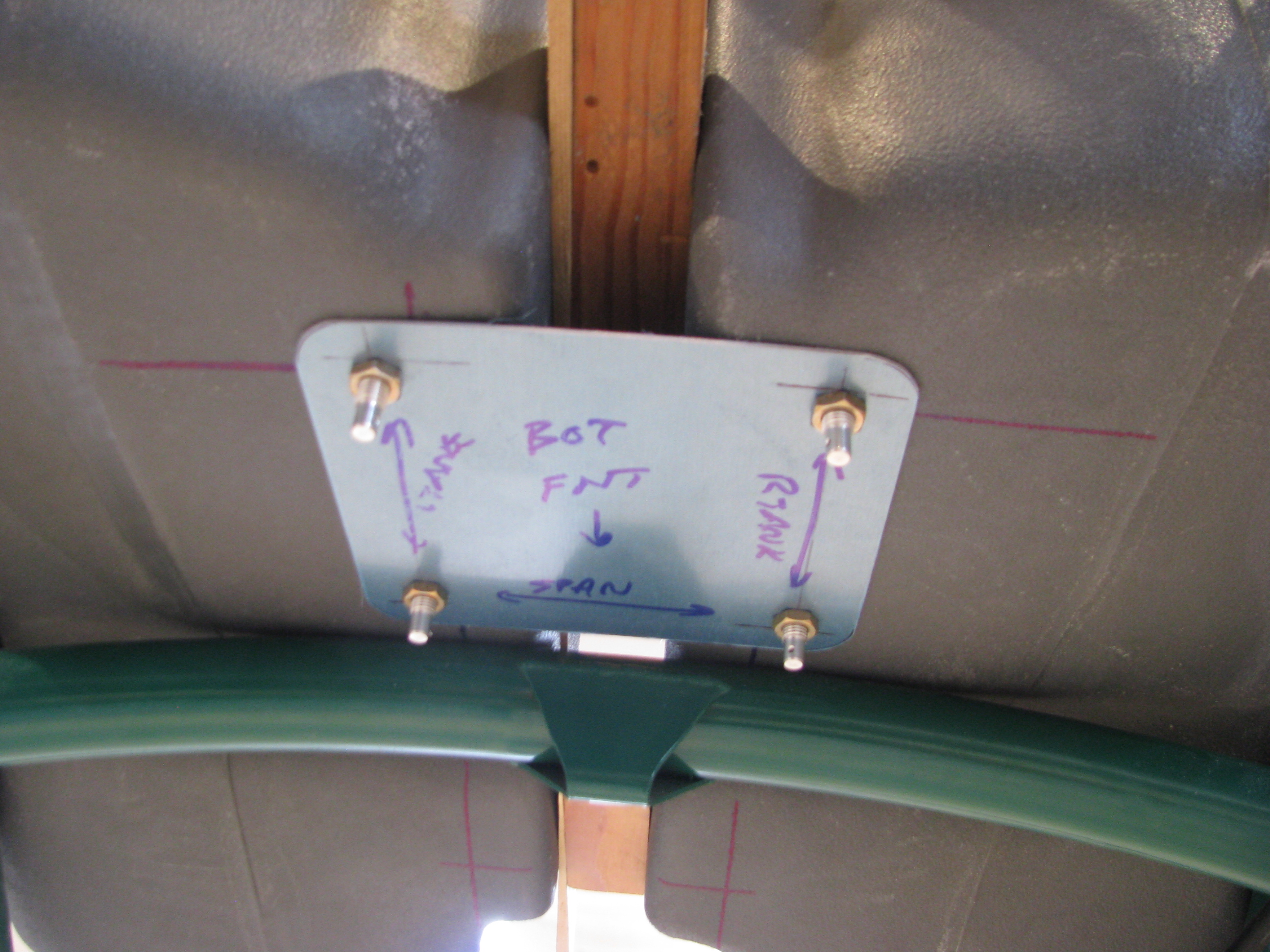
Fitting the lower tanks and drilling the spreader plates. I actually fished the little fittings through during the drilling op as they held the tanks more securely than just bolts pushed into position.
Plus, you’re doing this drilling upside down on your back, which is a little awkward.
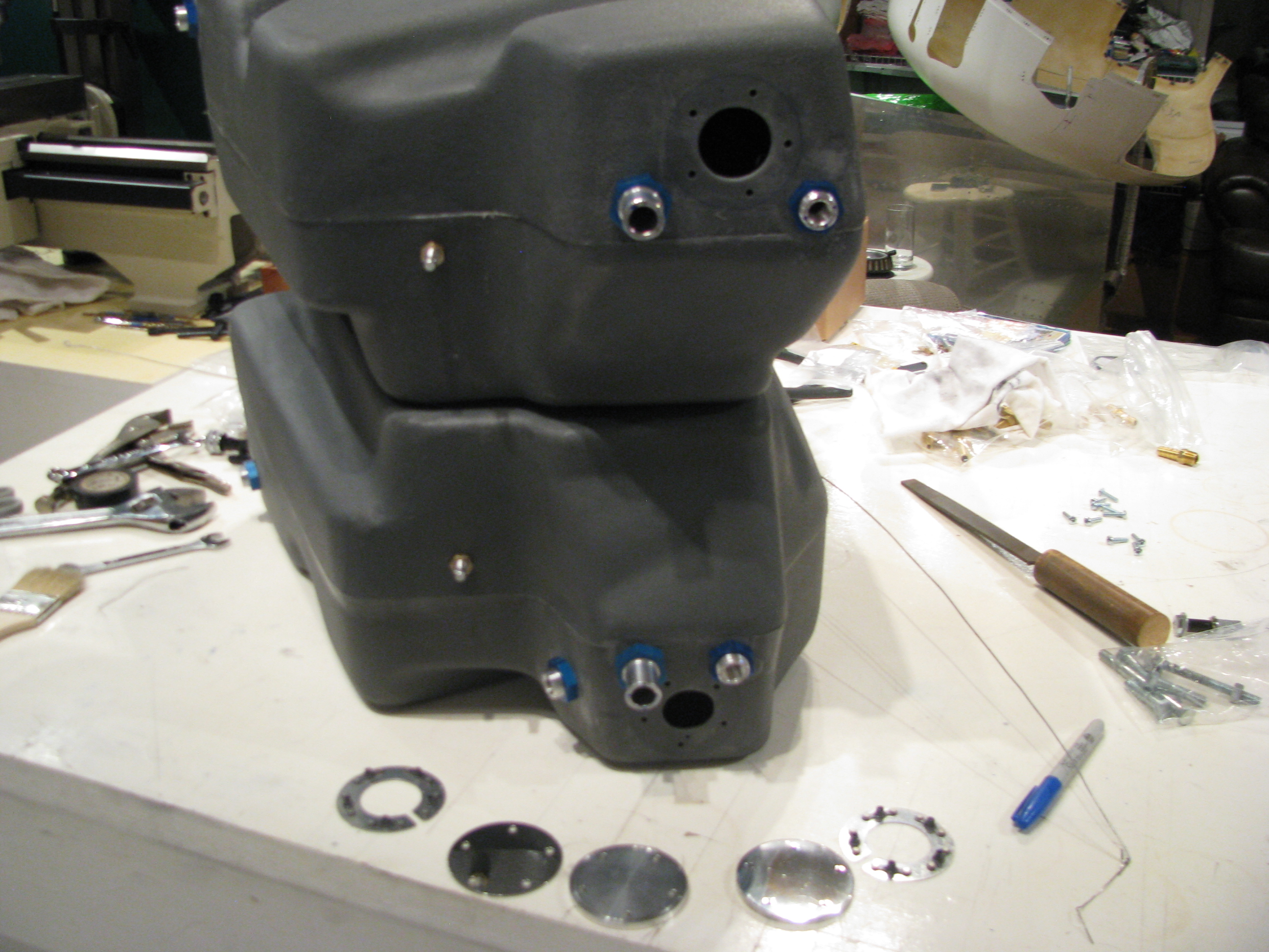
Fittings all installed in the lower tanks and the holes enlarged. I went ahead and drilled both cover plates. I do not plan on using the Westberg gauge and sender as I plan on using a fuel totalizer. In all the planes I have flown or owned I never use the fuel gauge. Time and total fuel actually used as reported by a totalizer has been far more accurate and reliable.
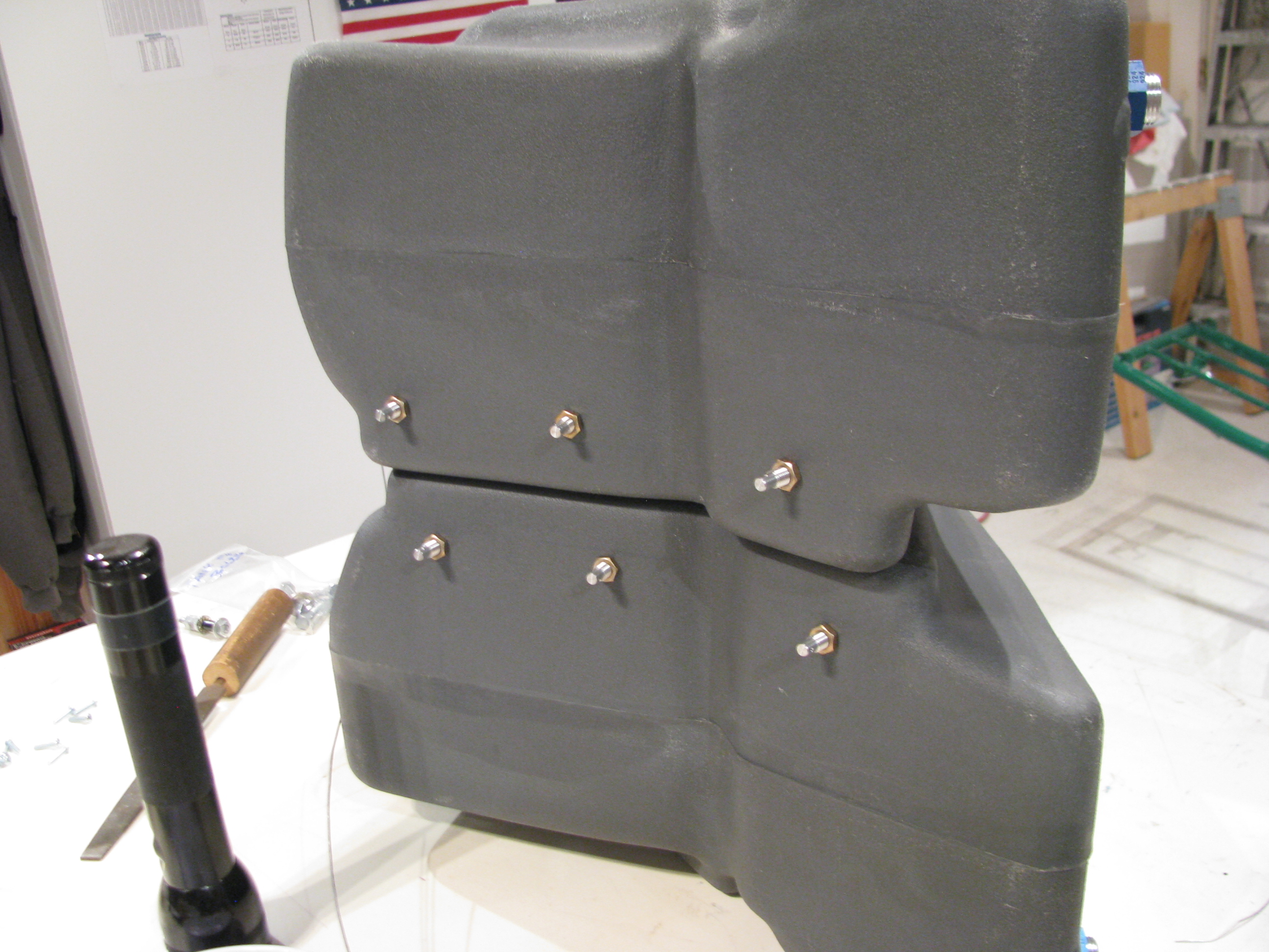
My Glasair gauges are useless as there is only a small band of gauge movement where they are actually in motion somewhere in the middle of the overall capacity. The totalizer is far more accurate.
Of course the thing you lose is the remote possibility of a catastrophic leak being detected in time to set it down before all fuel has leaked out. I’m willing to accept that.
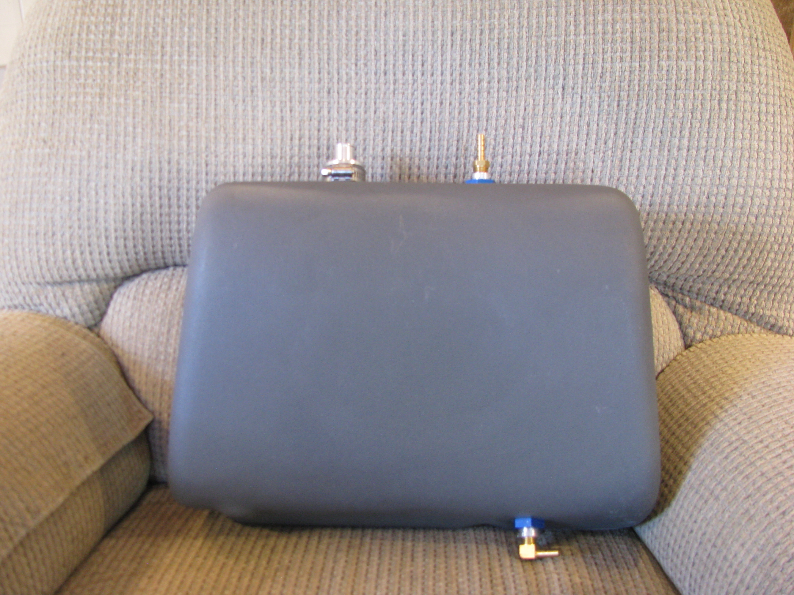
The aux tank is pretty easy. The only trick is that the upper opening (the large one) is not exactly a uniform cylinder. It took a bunch of sanding and trimming for the fitting to be persuaded in and to fit the O-ring securely.
The only issue that bothers me is that in order to screw in the brass fittings I will probably have to clamp the external threads to hold the fittings steady, which is bound to bugger the threads. That will prevent the inserts from ever being removed.
12/1/11 - I set to work fabricating the hold-down straps for the aux tank. I didn’t like the way BJ called for the strap to be simply bent and bolted to the back of the seat. Seemed like there would be a stress point right at the bolt, so I riveted on a couple of pieces of angle to better handle the 90 degree force turn.
The curve of the seatback also caused the straps to not sit flat, so I glued on some foam strips, poured in some flox, ground and sanded them flat and perpendicular, then glassed over the foam.
The close up shows a tiny little void in the glass in the lower right, but this is non structural, so we won’t panic. I am learning fiberglass and my results are getting better, but I won’t be building a Long-EZ yet.
I whipped up these little brackets to allow for snugging down the straps and taking up any excess slack in the straps themselves. Not much weight and it should be easier to make sure we’re tight and not moving around at all.
Using BJs method would be lighter, but you’d have to have the strap length absolutely perfect to have them reach the correct tension right as they bottom out. Probably not possible with the flexing of the tank.
One down. One to go. I need more of this jumbo shrink tubing and to paint them up on completion.
12/31/11 This is the fuel pump mount pad. The welds that mount the tabs to the frame extend up a little. Instead of grinding them down (weakening the joint and breaking the powdercoat) I just made this 0.050 shim in the shape fo the fuel pump base. It’s as thick as the welds and everything sits flat now.
Done for now. The tanks have been preliminarily fit, the hoses have been cut, and everything looks good. I have a fuel flow gauge and sender on order. When they get here I will seal it all up and do a leak check and be done with fuel until final assembly.
One note: I did elect to forego the Westberg sender and gauge since it seemed like a pretty expensive way to only measure the lower tank. I saw a video on the web of one builder who ran a sight gauge in the cockpit along the back interior edge of the seat pan. Pretty primitive, but an effective way to see the real level from the top to the bottom. I am thinking this is the way I’ll go as a gauge of last resort. The fuel flow meter will be primary with the visual sight level as backup.
More Training Toward Ticket
Still Training
Two weeks of rain followed and there goes a whole month without flying a helicopter. I got up this weekend, but am off to Taiwan next week, so who knows how much longer this will drag on. Halloween was the target. Maybe Thanksgiving at this rate.
Chin Window Drilling & Cabin Fiberglass
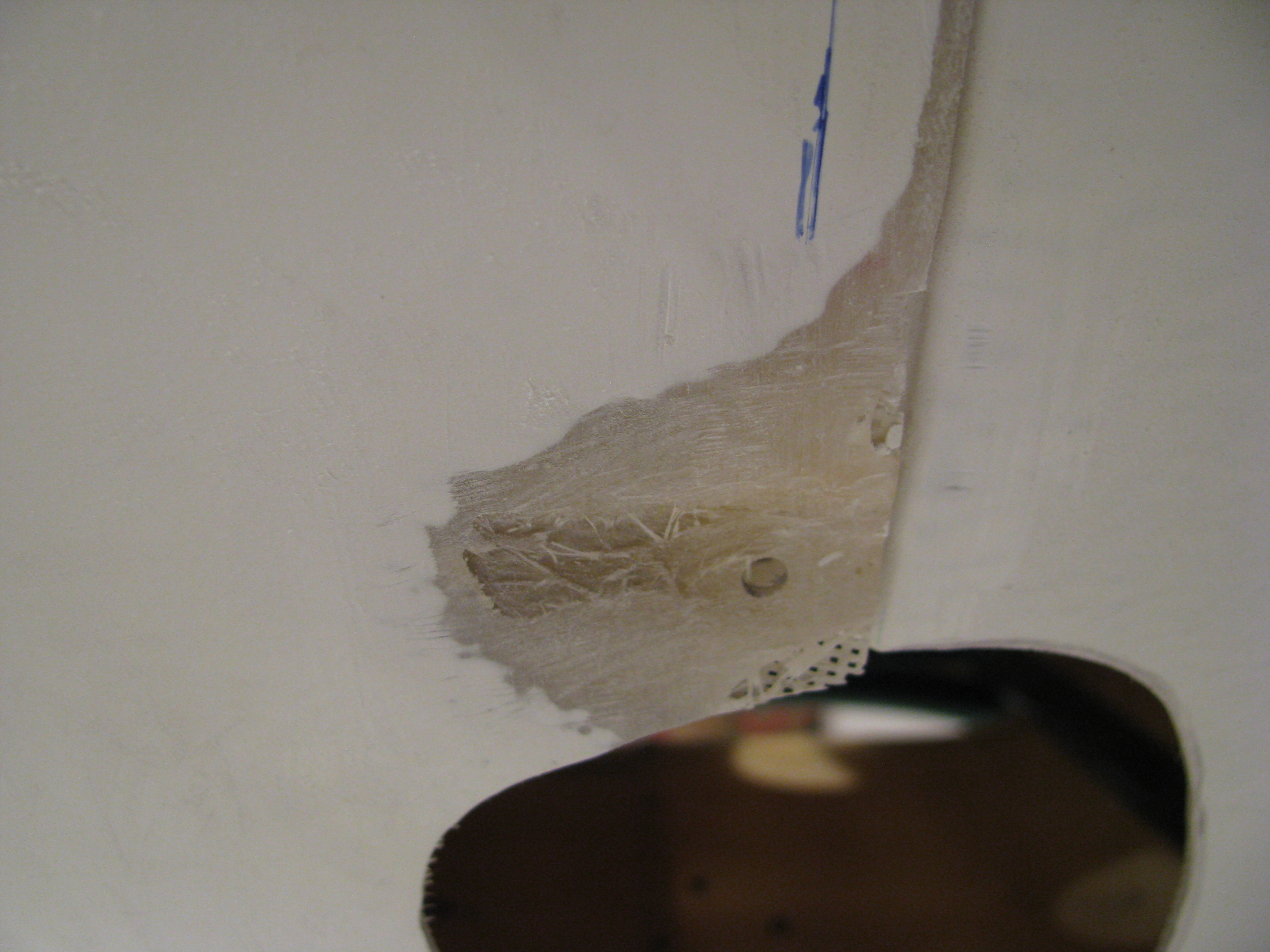
Cleaning up a lot of little things. Here is a spot on the body that was bubbled and mostly gelcoat. Ground it out, heat and flattened the fiberglass with a heatgun and pressed it between some angle to straighten . Finally layed up a couple of thin layers to add strength and bondoed to smooth it out.
There were a couple of spots that required this treatment.
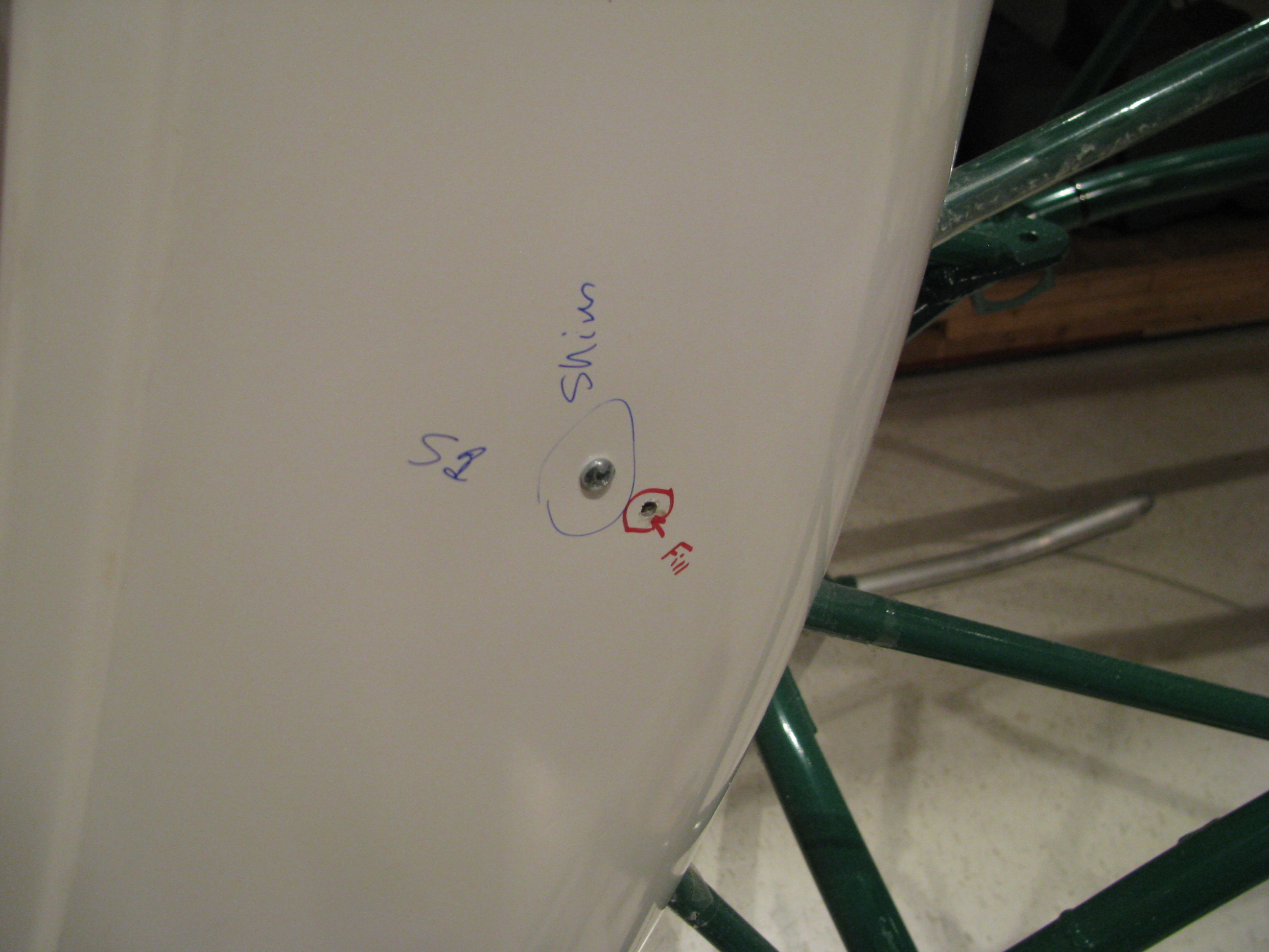
Here is where the pre-drilled holes didn’t quite line up with where the floorpan actually fell. Had to drill a new one and fill the old.
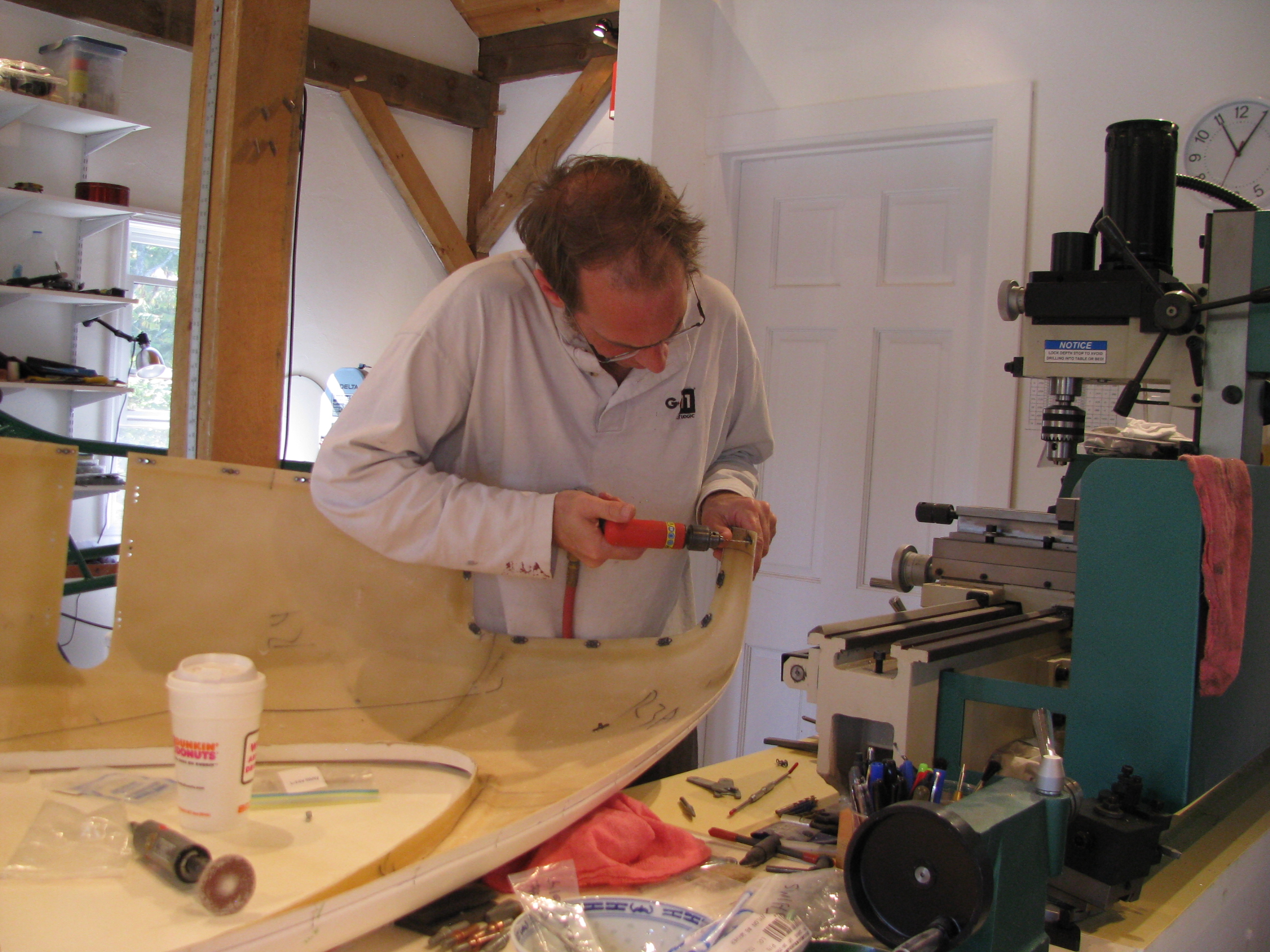
FAA required picture of me working. Gotta remember to get more of these. Since I am usually working alone it means getting out the tripod and setting up the camera timer. Coffee fueled build process.
Holes are easy to drill, but each one needs a nutplate and there sure are a lot of them. Here I am drilling and mounting the chin window floating nutplates.
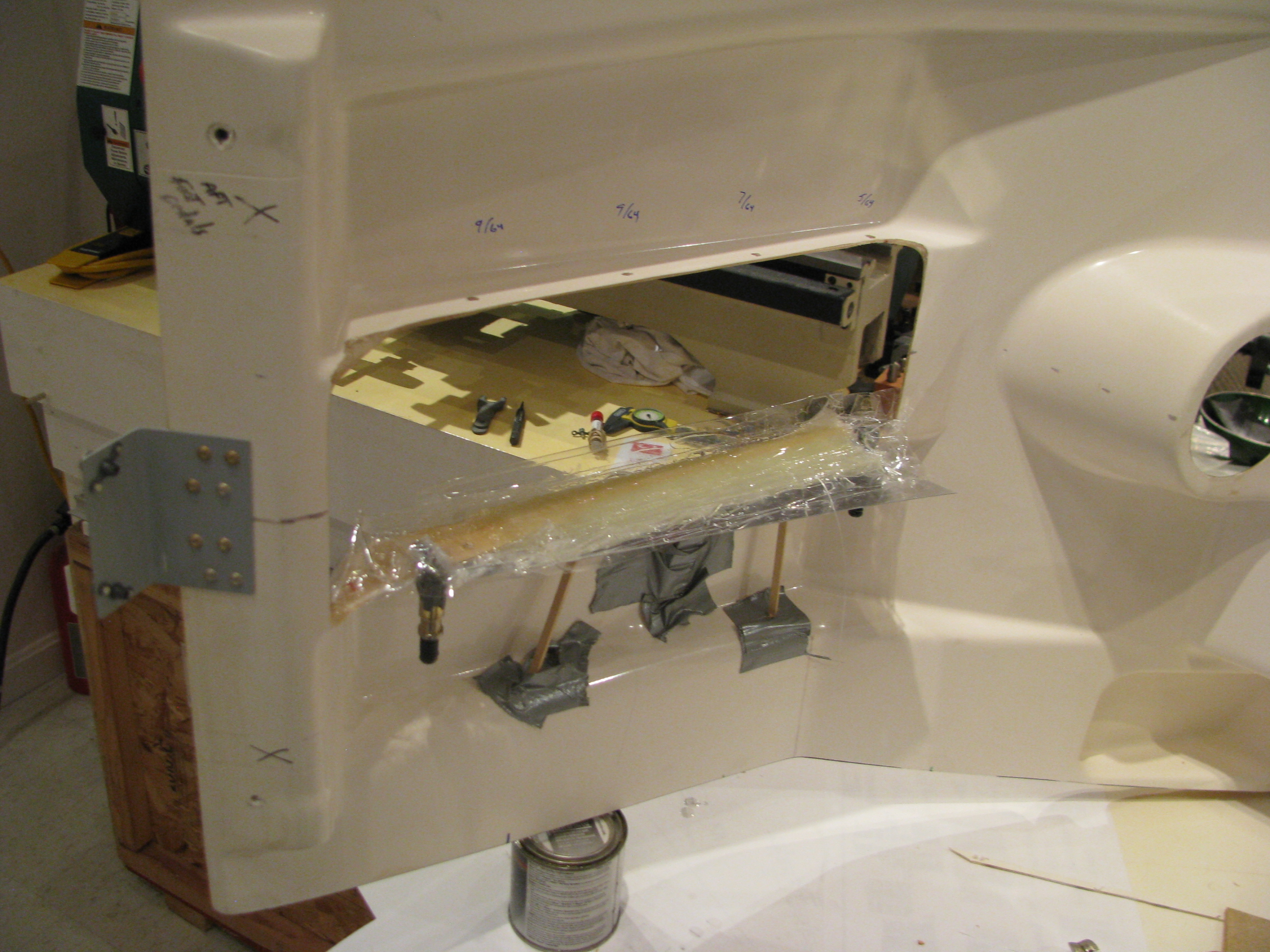
There’s a lot more fiberglass work than I anticipated. This is the lip of the floorpan along the base of the instrument pod. The drilled holes cut through the edge of the lip.
I had to first cut away the fiberglass with the partial holes. A dam was built with packing tape and a tape covered aluminum sheet. Then an thin layer of flox to allow the edge to form, then five layers of cloth. I’ll have to sand a lot of it down, but it should allow for a tight fit with plenty of meat around the holes. It’ll be a lot “taller” than the original lip.
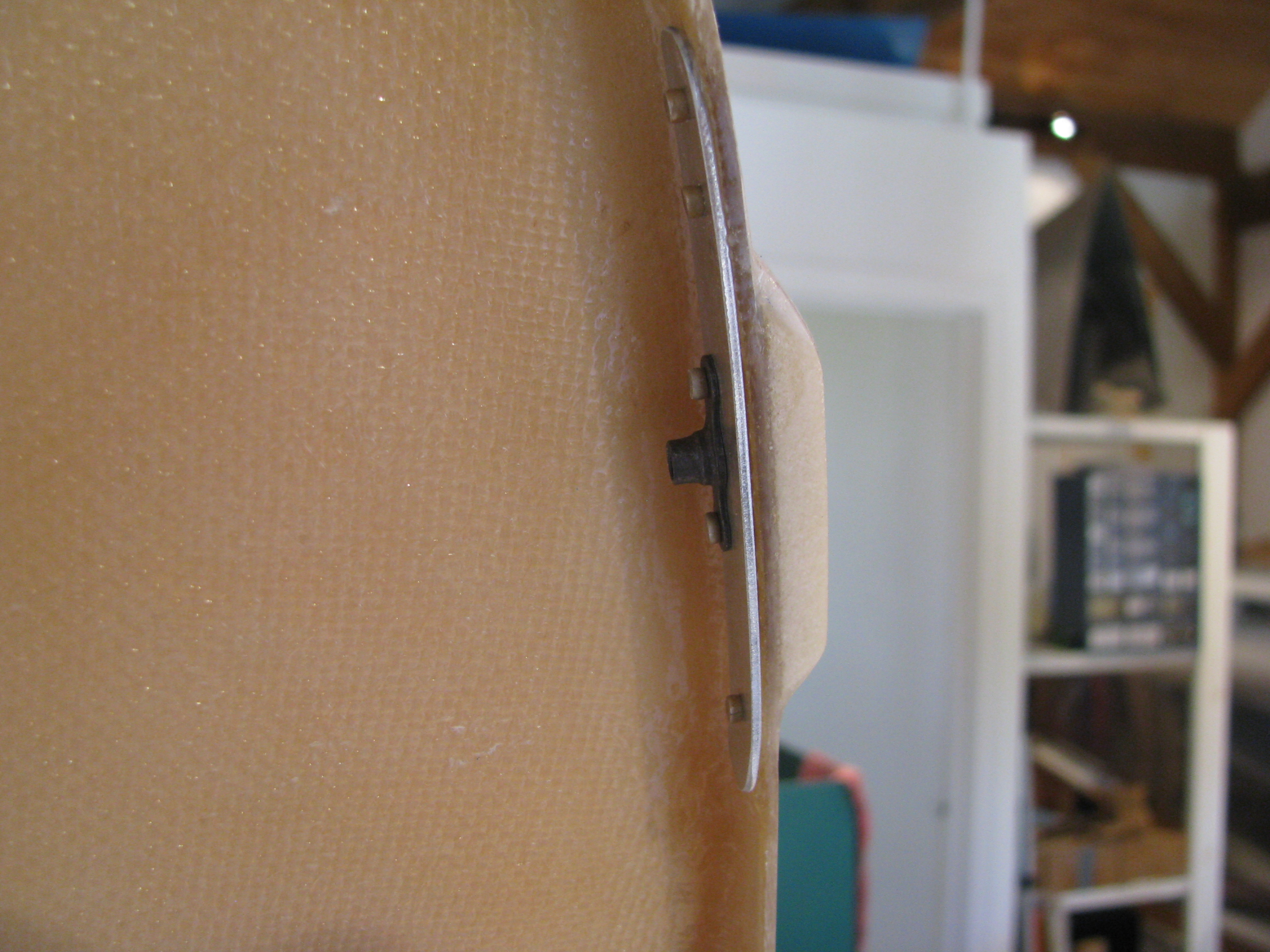
In a few places I had to shim the pan, especially up around the curve of the top of the body. A layer of foam sanded to the correct thickness, then glassed over. To mount the nutplates behind the lip I had to cut a strip of aluminum, mount the nutplate, then rivet it outside the foamed area.
Initial Fuel System Work

The fuel system on a Helicycle is relatively complex compared to “normal” aircraft. There are a couple of reasons for this. First, the turbine is very thirsty and needs large capacity. Second, the fuel must be centered on or near the CG since this is a light, single-place machine.
Consequently, there are four different tanks and the associated plumbing and interconnect. Management is easy, though. Since everything gravity feeds to the lowest point where the pickup resides, there is no switching or pilot involvement required other than making sure you don’t run out.
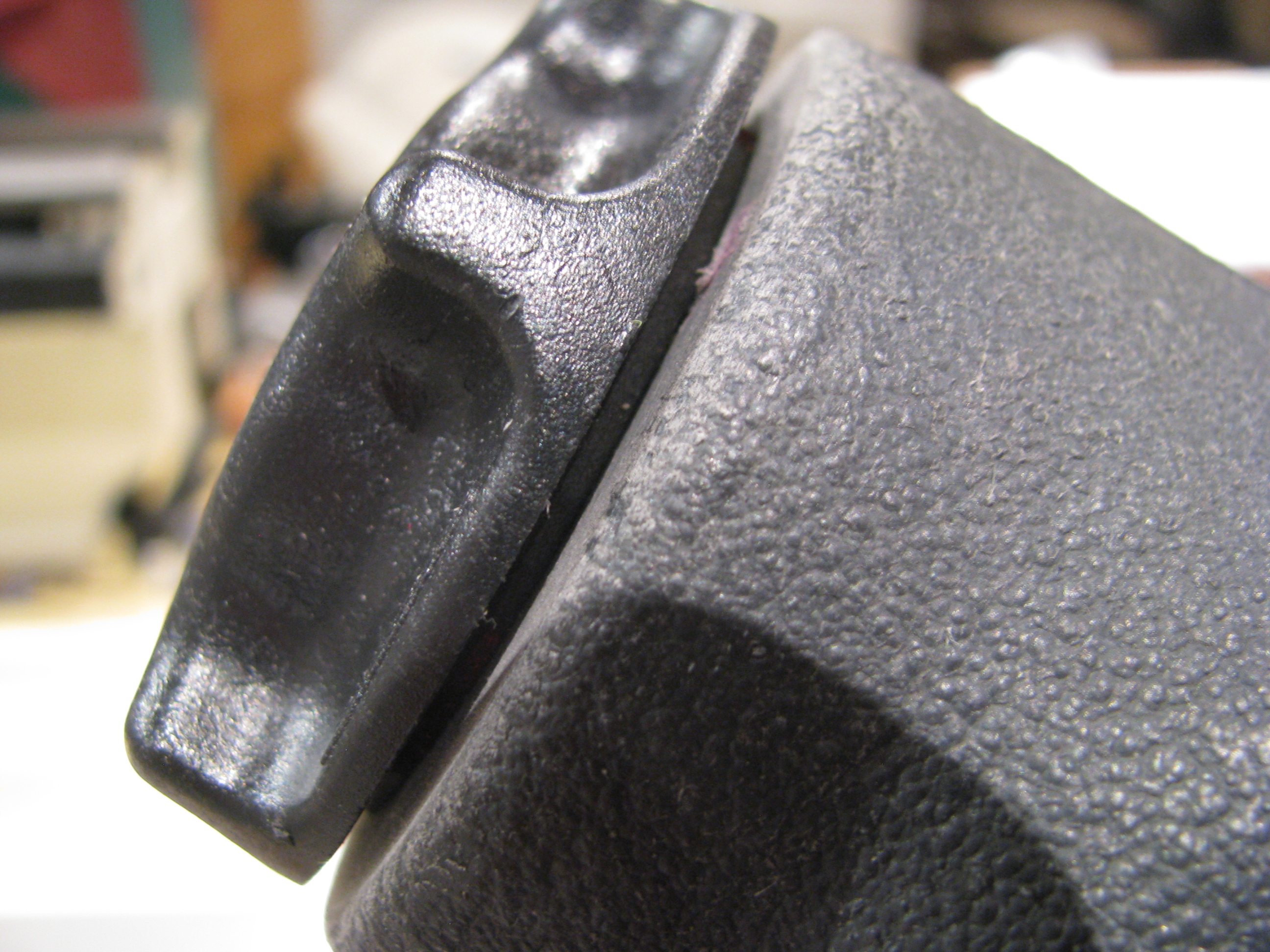
The first thing BJ has you do is to file a bit off the cap threads to allow it to screw in snugly, but smoothly. Easy and quick.
Next is to file the gasket area flush for a good seal. The tank is relatively thin, so don’t be ham handed with the sanding.
A lot of guys seem to modify the gas cap area to allow for better Jet-A fueling options. Maybe I will too, but not until the machine is built to the plans first. Gotta finish, then modify.
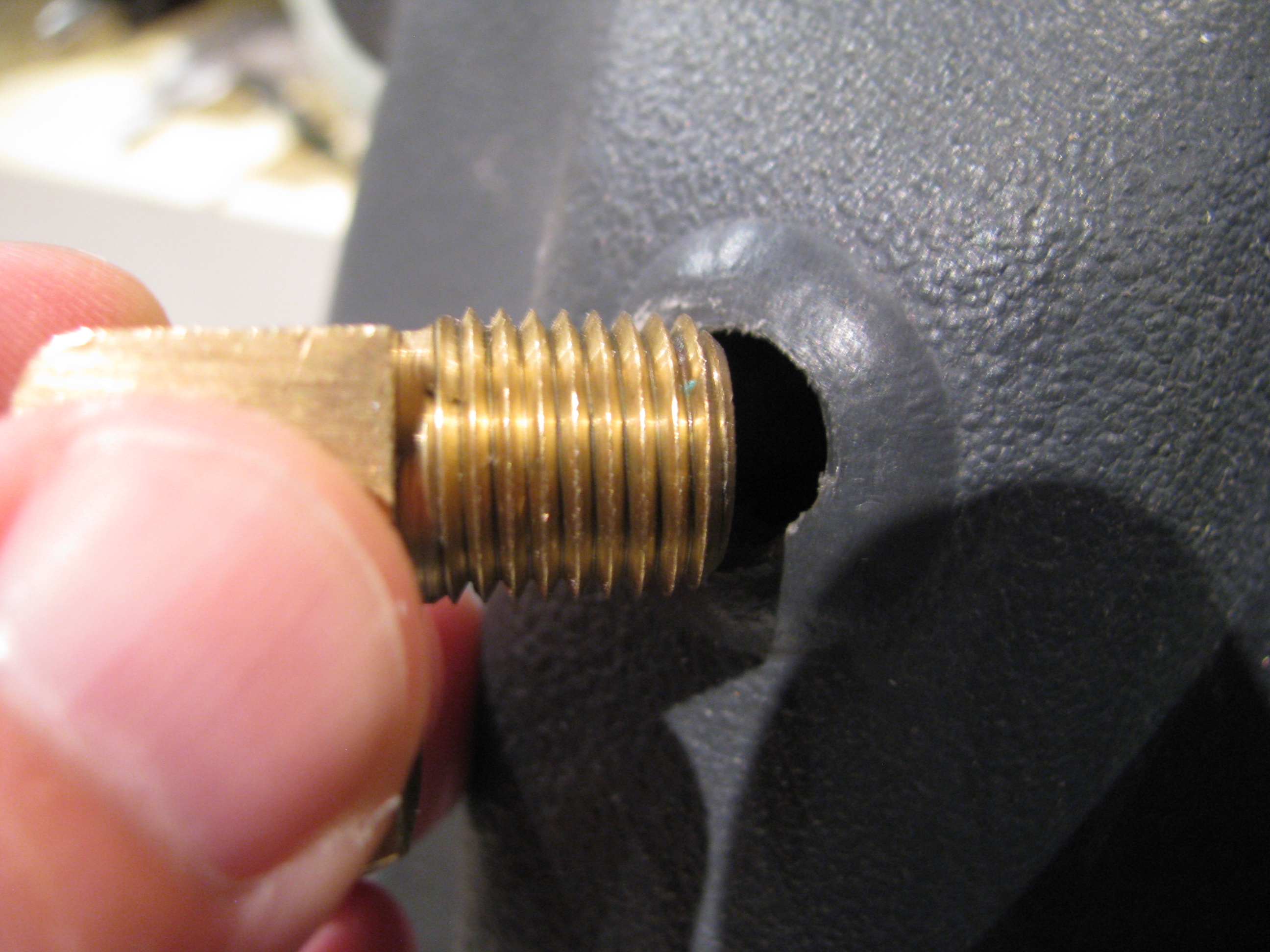
Next is fitting the air vent street elbow. There was no way mine was going to fit, so the next time I was at Harbor Freight I picked up a 1/4” NPT tap ($6 for a set of three- amazing).
Just tap enough to get it started (maybe one turn), otherwise it’ll probably be too much. The threaded area is pretty thin overall.
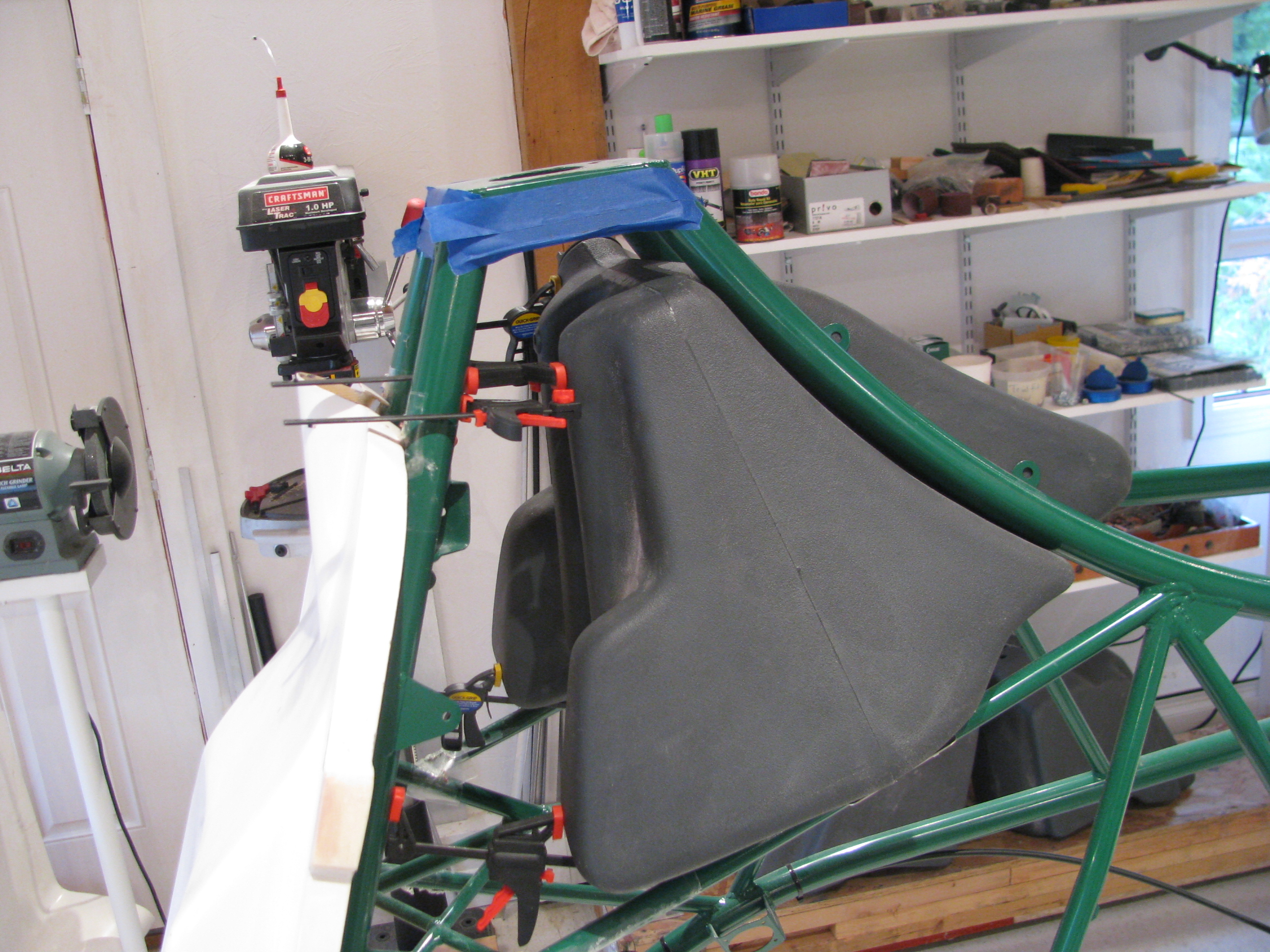
Quick Clamps with the jaws reversed so that they “separate” instead of “clamp” seem to work well to shove the tank back up against the frame tubes in preparation for drilling the mounting holes.
BJ has the tank base plates just tie-wrapped on. Even my dad thought that looked chinzy, so I may end up doing something beefier before final installation.
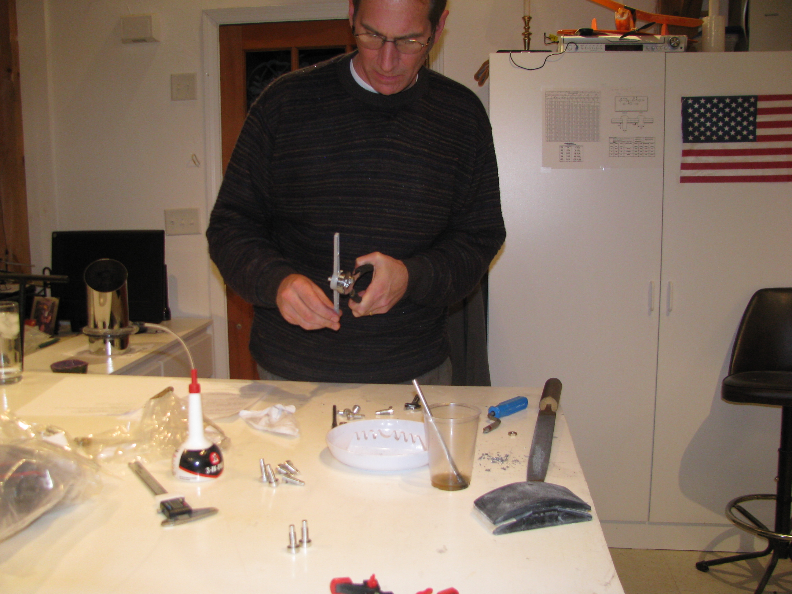
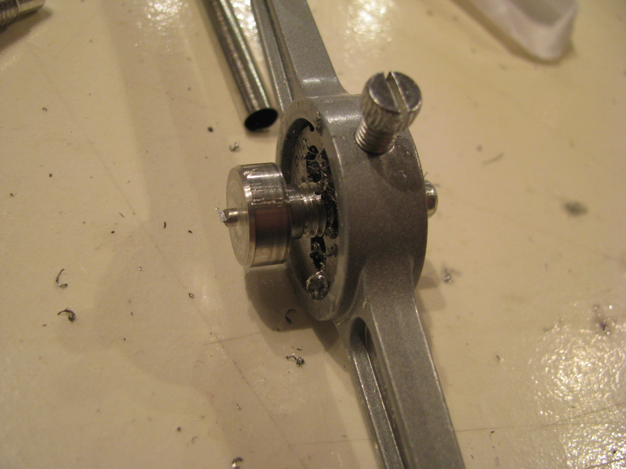
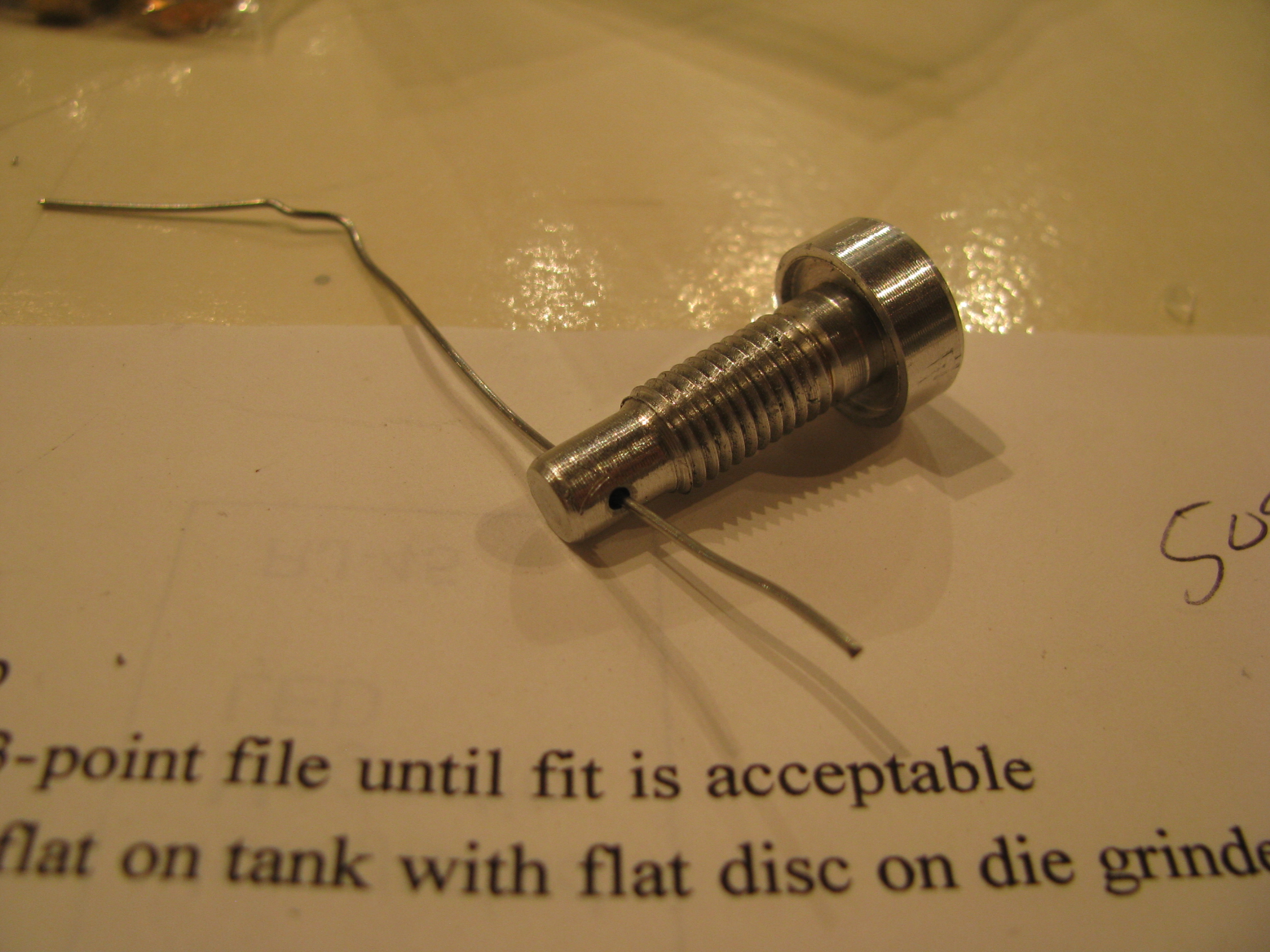
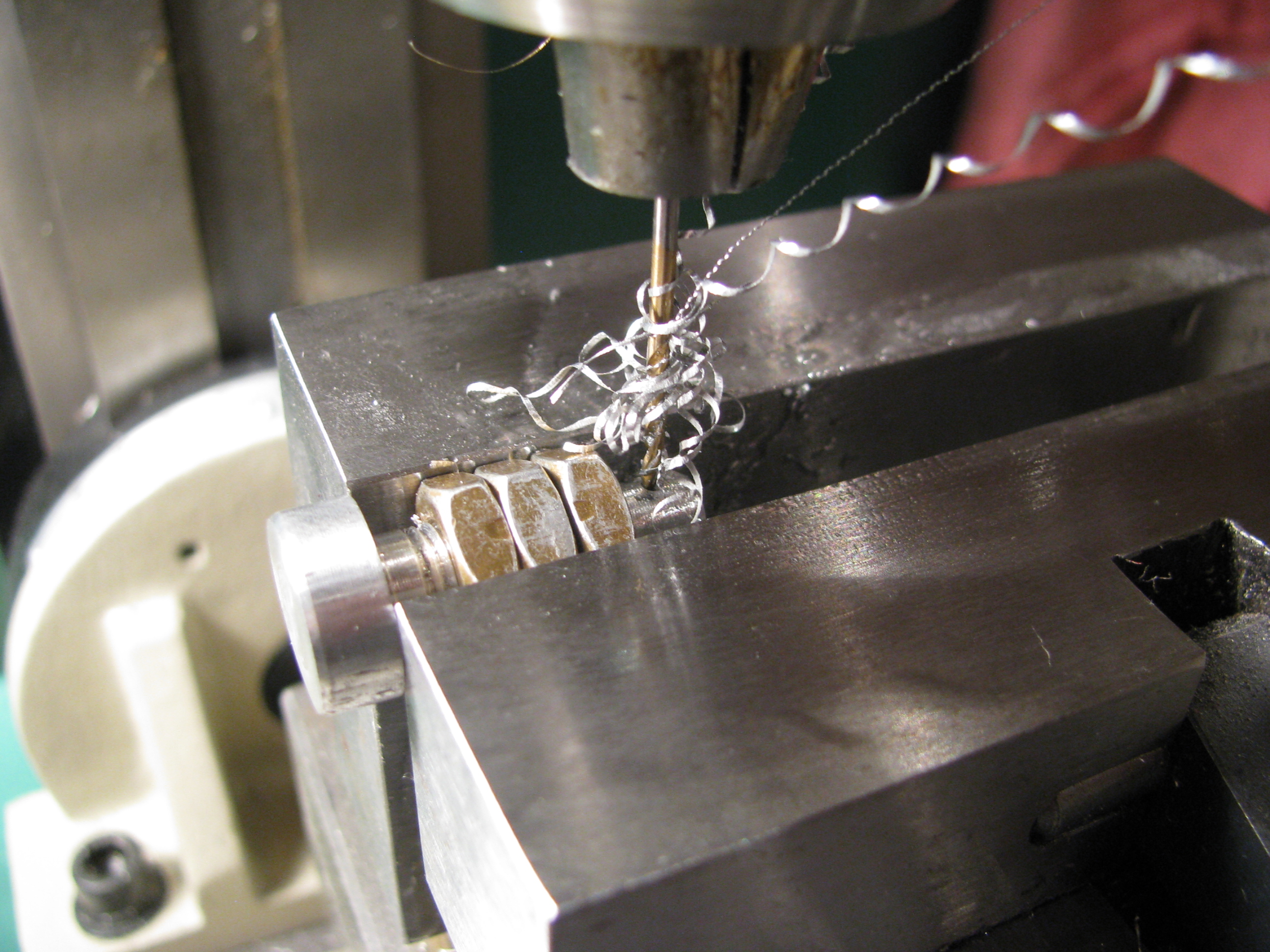
The machined tank mount bolt plugs were a little snug for the nuts. They had to be cleaned up with a 5/16-24 die, then the holes for the “fishing wire” drilled into the end portion. Another ad for the mill/drill. Quick and easy to center the holes. And of course a picture of me for the FAA.
Slogging Through Requirements
10 hours solo with 3 of cross country. 3 hours night time. Night cross country. Controlled traffic patterns. Pinnacles. Confined Areas. Slopes. Autos. Autos. Autos. 3 hours checkride prep. Now it’s time to hit the books and maybe put in another 2 hours to sharpen everything up and hit my spots. Then we’ll see how it goes. I had hoped to have this done by Reno, but maybe by Halloween.
Drilling Windscreen & Bodywork
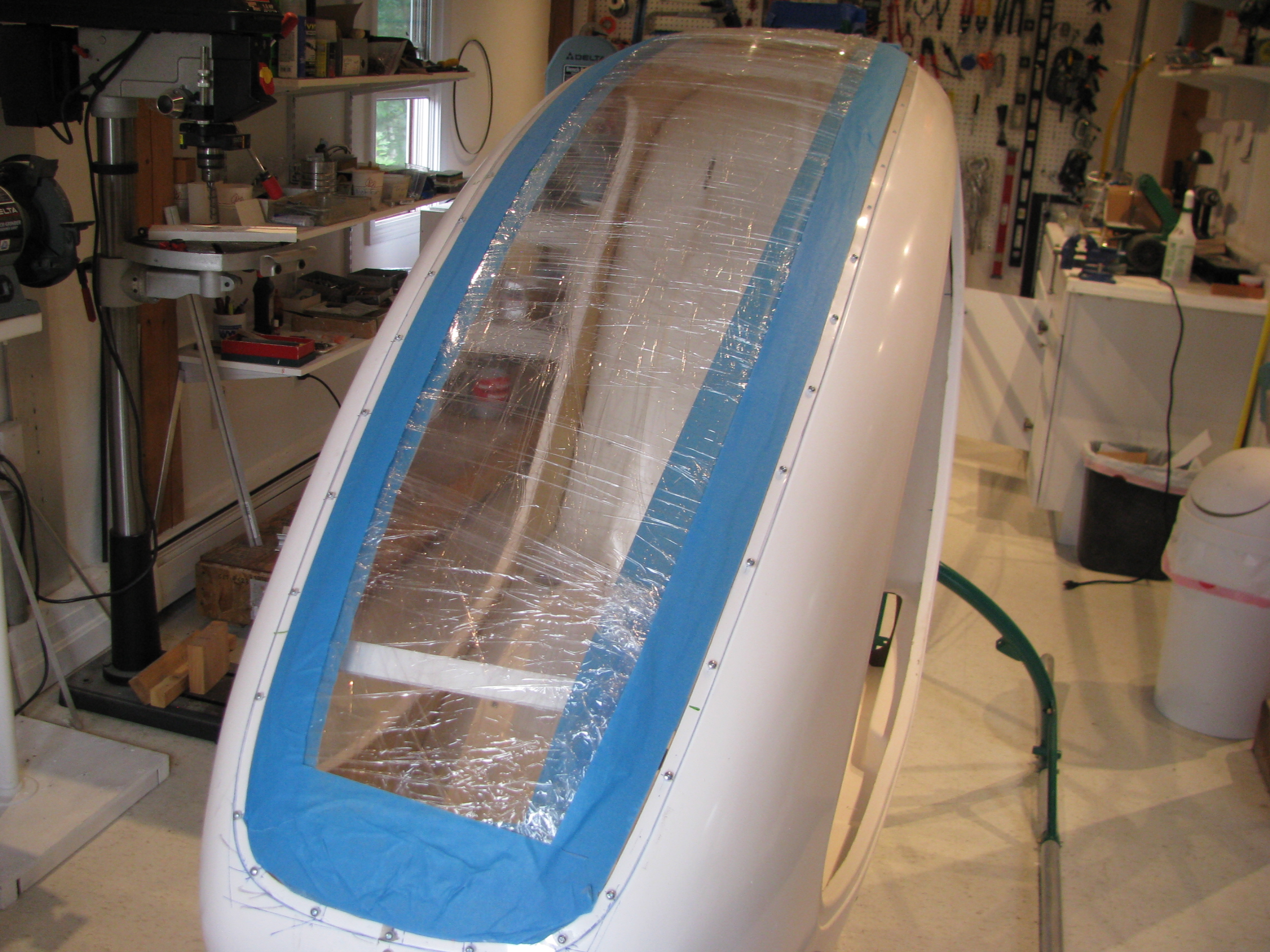
It’s been a few weeks with slow progress. I fitted and trimmed the windscreen and lower plexi and drilled them to the frame.
The windscreen and lower window really add a lot of strength to the cabin. It’s pretty solid now. My shop was about 90 degrees, so the plexi was pretty flexible and the holes drilled cleanly. Only a few will need some sanding and beveling as there looks to be a chip or two on the backside.
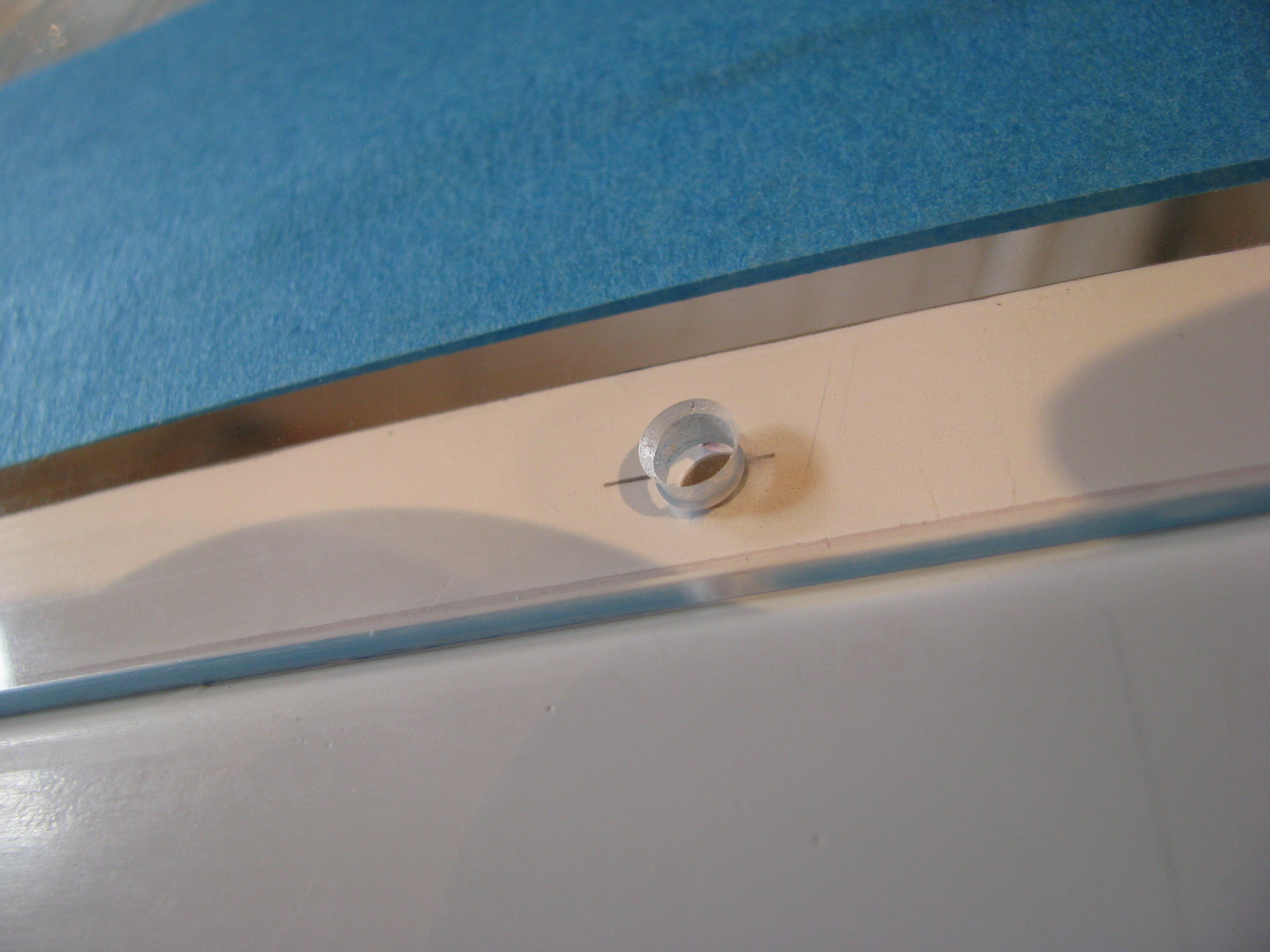
Most of the holes look like this after drilling and beveling. Overall I am pleased with the result
Initial Screen Fitting
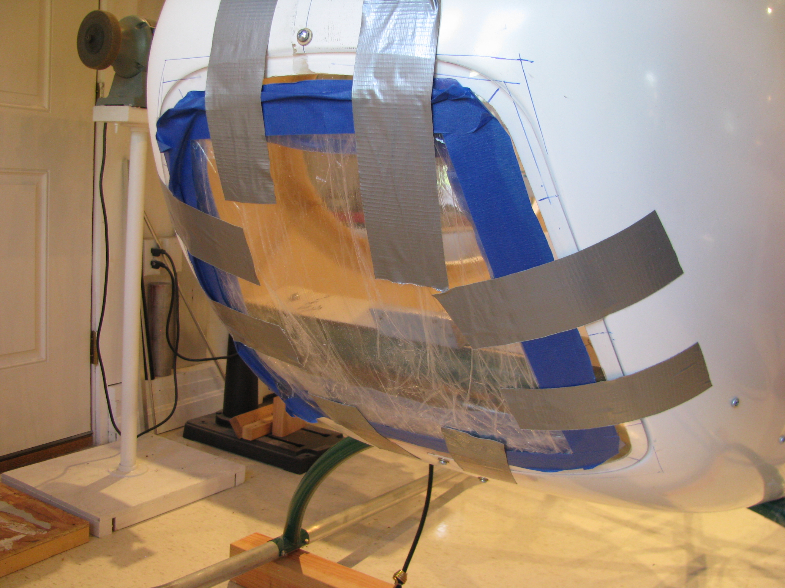
Lower plexi taped in place on front. Lot’s of trimming to fit the joggle cleanly. It has been drilled and I purchased a bunch of #6 floating nutplates after having read the experiences of others. Apparently with the instrument cluster in place there is almost no way to get your hands in there to place acorn nuts.
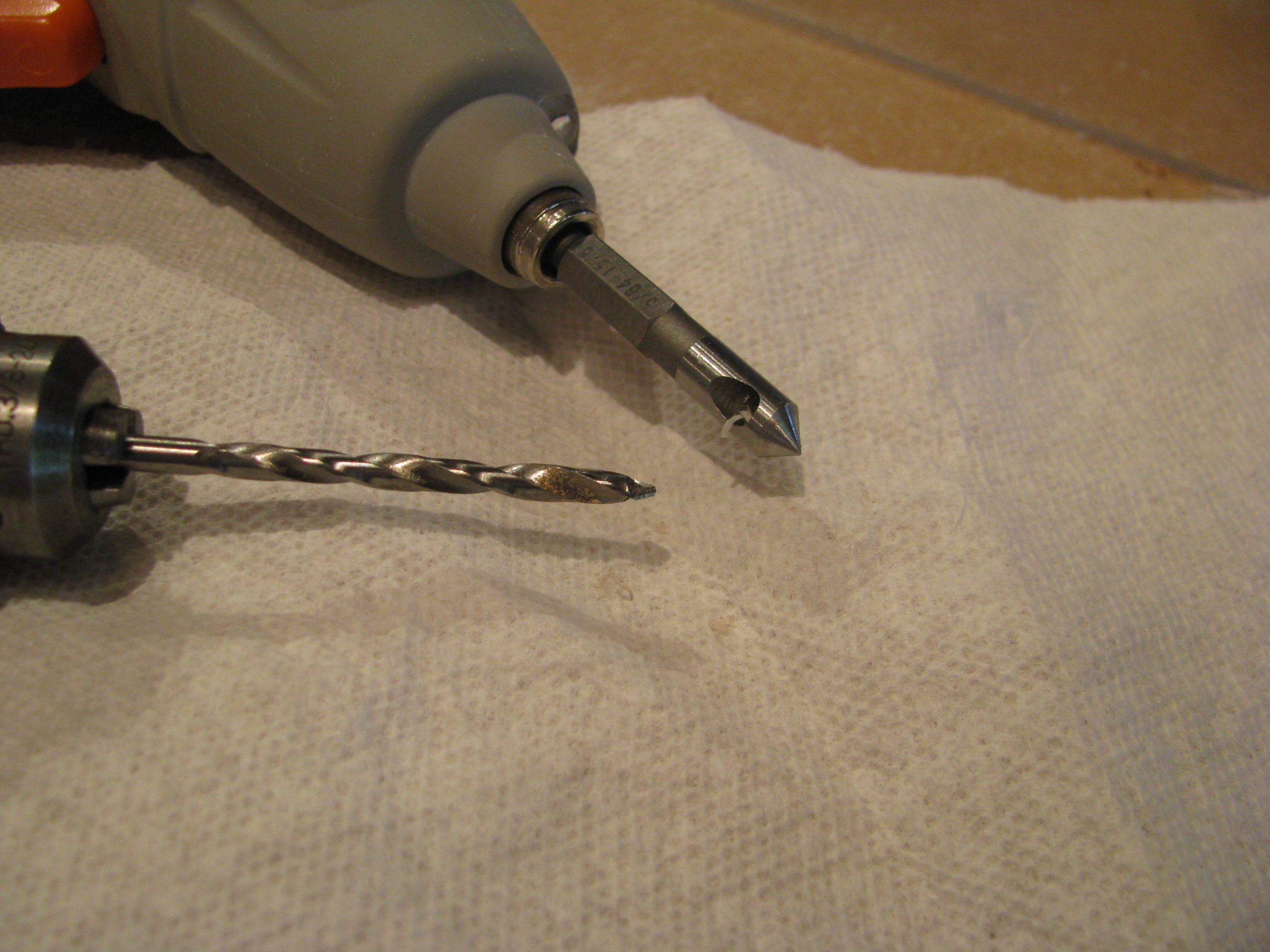
Here is my dynamic duo for drilling the plexi. The drill bit is a #27 plexi bit from Avery Tool. It has a shallow cutting 60 degree point. The countersink I picked up from the sale bin at Harbor Freight. It has a single flute and just barely shaves, which leaves a nice, chatter-free chamfer on the plexi holes. $3.99 for a set of three. It would probably dull immediately on aluminum or steel, but it’s great for this application.
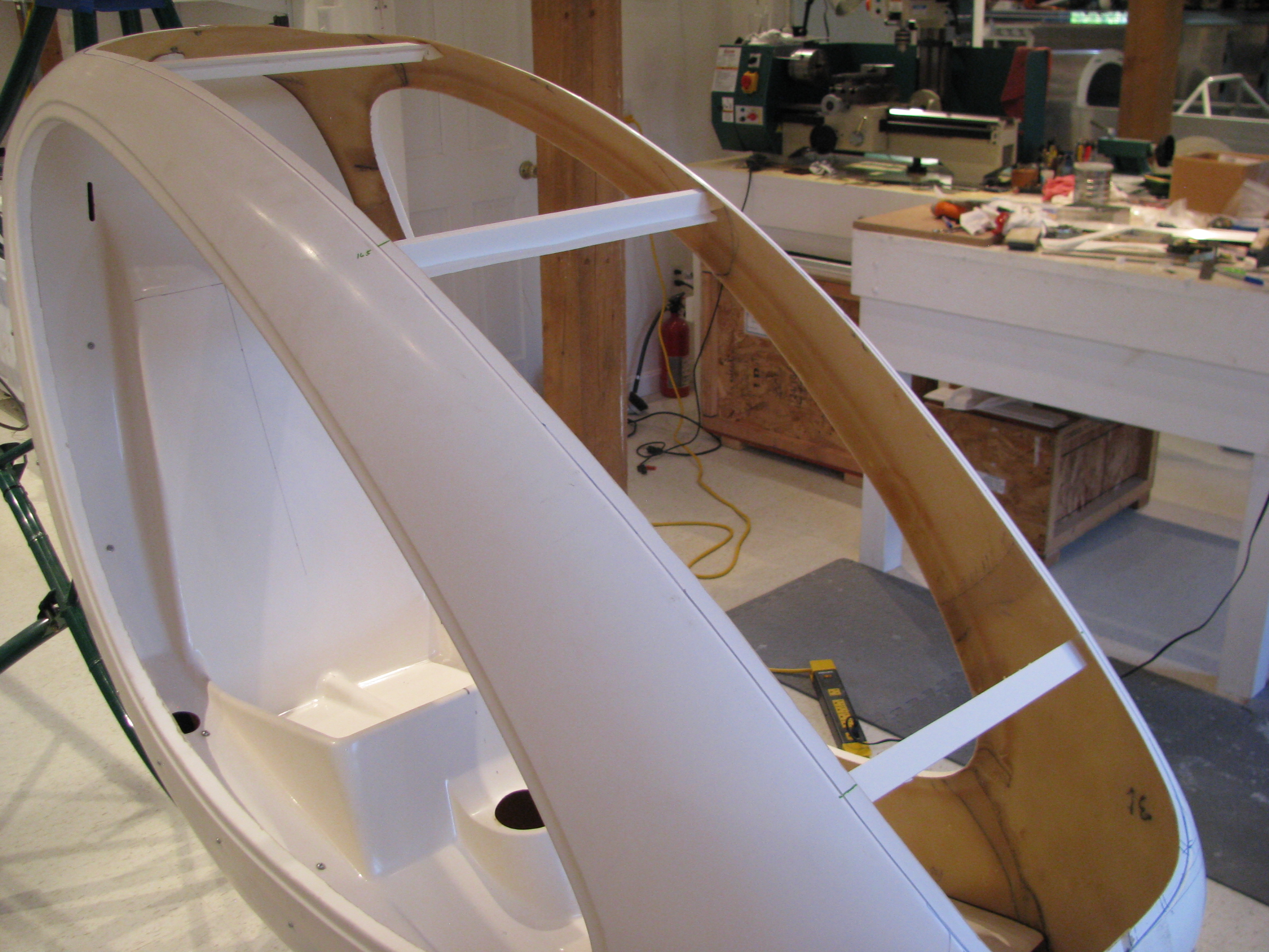
The windscreen opening is pretty floppy without the windscreen. I hot glued some foamcore “I-beams” to hold the width to almost exactly match the windscreen. Makes fitting and holding the windscreen in place much easier. I thought peeling the hotglue out would be easy when I’m done, but I tried peeling off a blob and it really, really grips that rough fiberglass pretty securely in fact. Oh well.
Drilling Cabing Halves
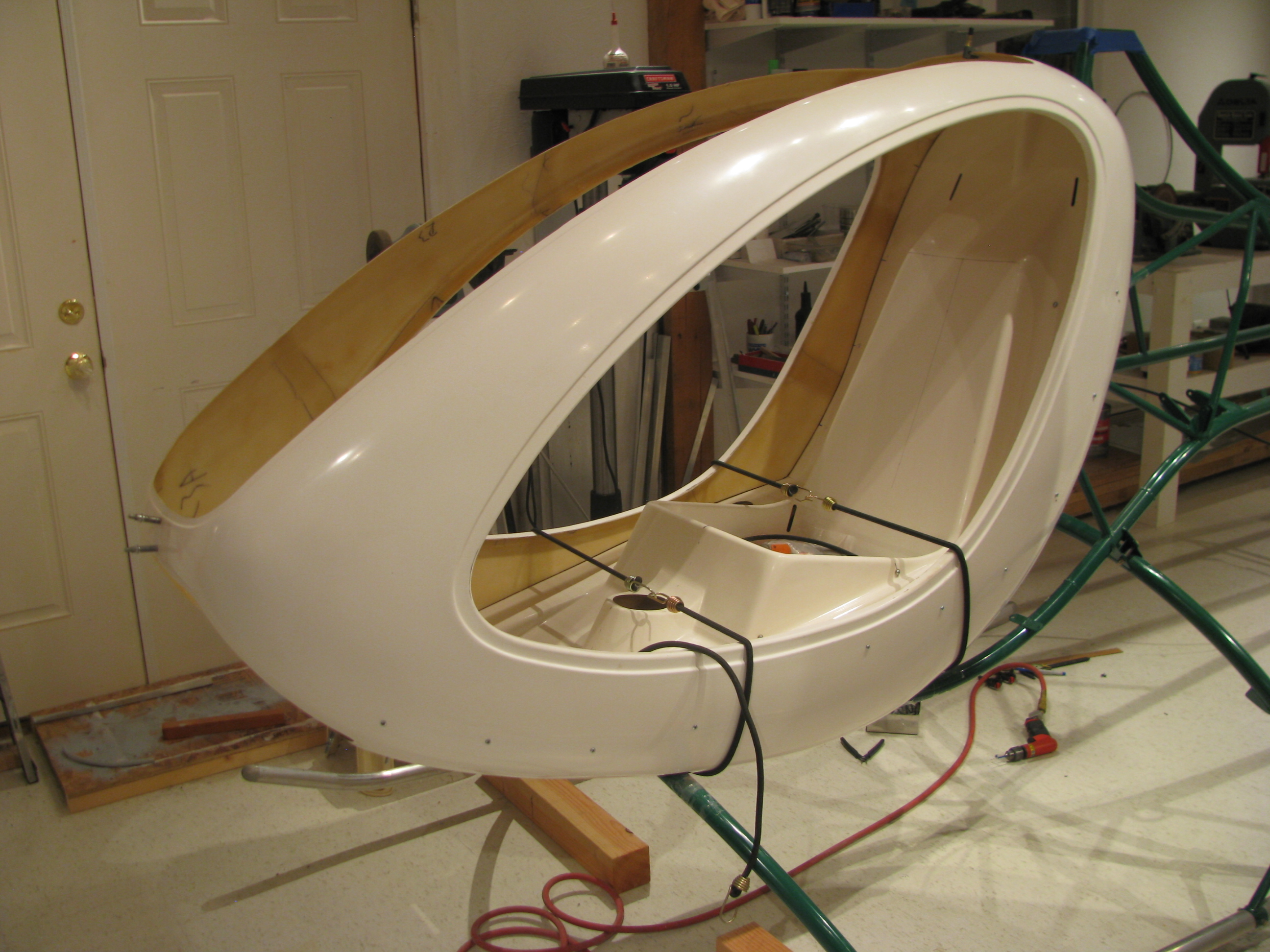
Body halves drilled all around. Straps, cleco clamps, and an extra pair of hands helps here a lot There are really no straight lines or easy reference points to tell whether it’s square and symmetric. Lots of fitting, standing back and eyeballing, then tweaking to make it as square as possible. About 14 or 15 screws from the front to the seatpan top curve. I’ll shim and drill the very top of the seatpan curve once the windscreen is in place.
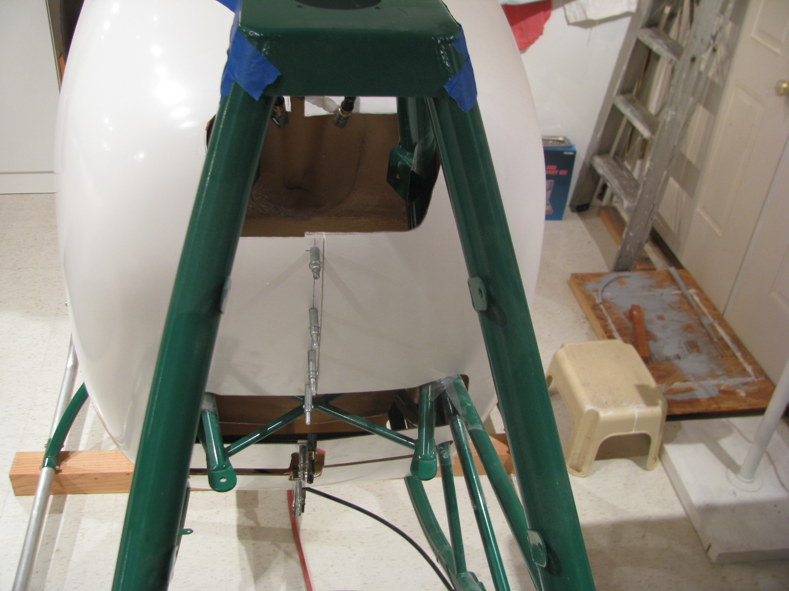
Rear of the body. The cutouts don’t match exactly, but that’s OK. I’ll trim them in place.
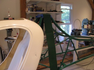
I found some green felt that is a very good match to the frame powder coat color. I will use some spray adhesive and use that on the body shell interior when I get to that point.
First Cabin Fit
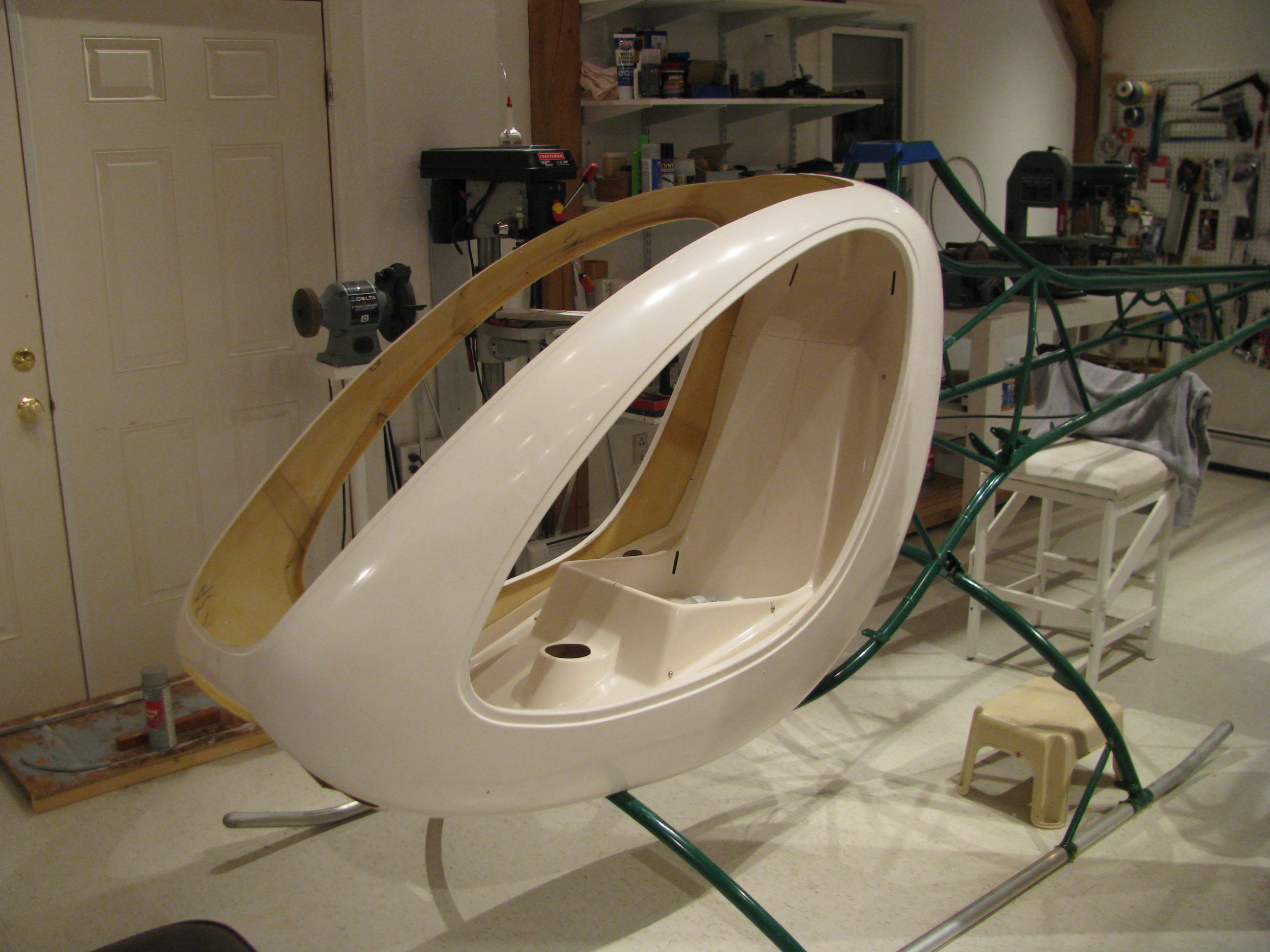
First fitting of the body halves. Of course they had to come off and on about a half dozen times to fine tune the cutouts around the body tubes. The powder coat on the body tubes got fairly scratched up in a few places before I had them all taped up to protect them, I’ll have to get some touch up paint of the same color.
The fit is pretty poor. I think my seatpan sits forward perhaps too much which makes the vertical holes on the sides impossible to line up on the left side without really deforming the seatpan. I may have to pull it all apart and redo the seat pan mounts so everything fits more cleanly. Darn. I thought this was going to be an easy bit.
Anyway, it really looks like a flying machine with the body attached and I had to strongly resist the urge to climb in, make airplane noises, and daydream. The frame came powder coated dark green. I had been thinking dark yellow for the body, but perhaps a very stark white would work with polished skids and blades and grey Zolotone on the interior. Too soon??
Instrument Pod Bracket
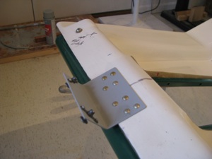
The front bracket is riveted on to stabilize the instrument pod. I have a lot of solid rivets in stock from my RV project and use them wherever possible instead of pop rivets.
Pan Drilling
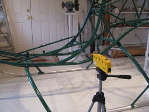
To drill the “blind” hole I first marked the arc at the correct distance, and also lined up a laser level with the hole from the outside. I started with a tiny bit and worked up to final, tweaking the position while checking from the inside.
It was only maybe 10 mils off by the time I got to final size. Not bad.
Confined Area Training
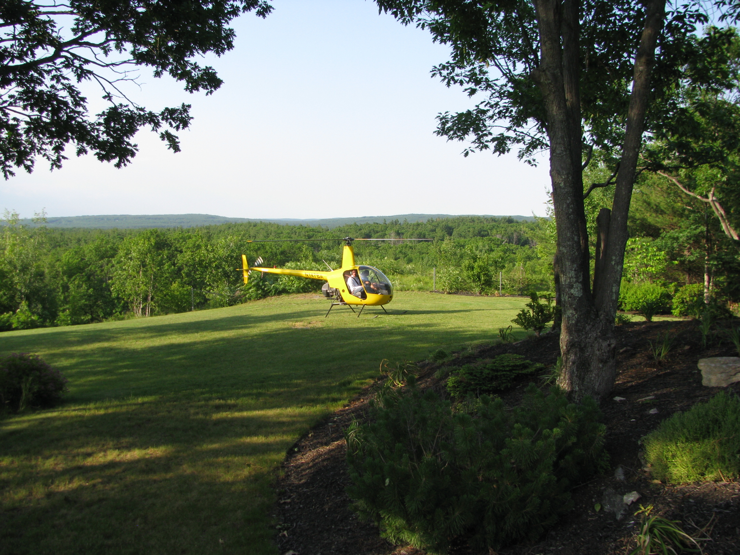
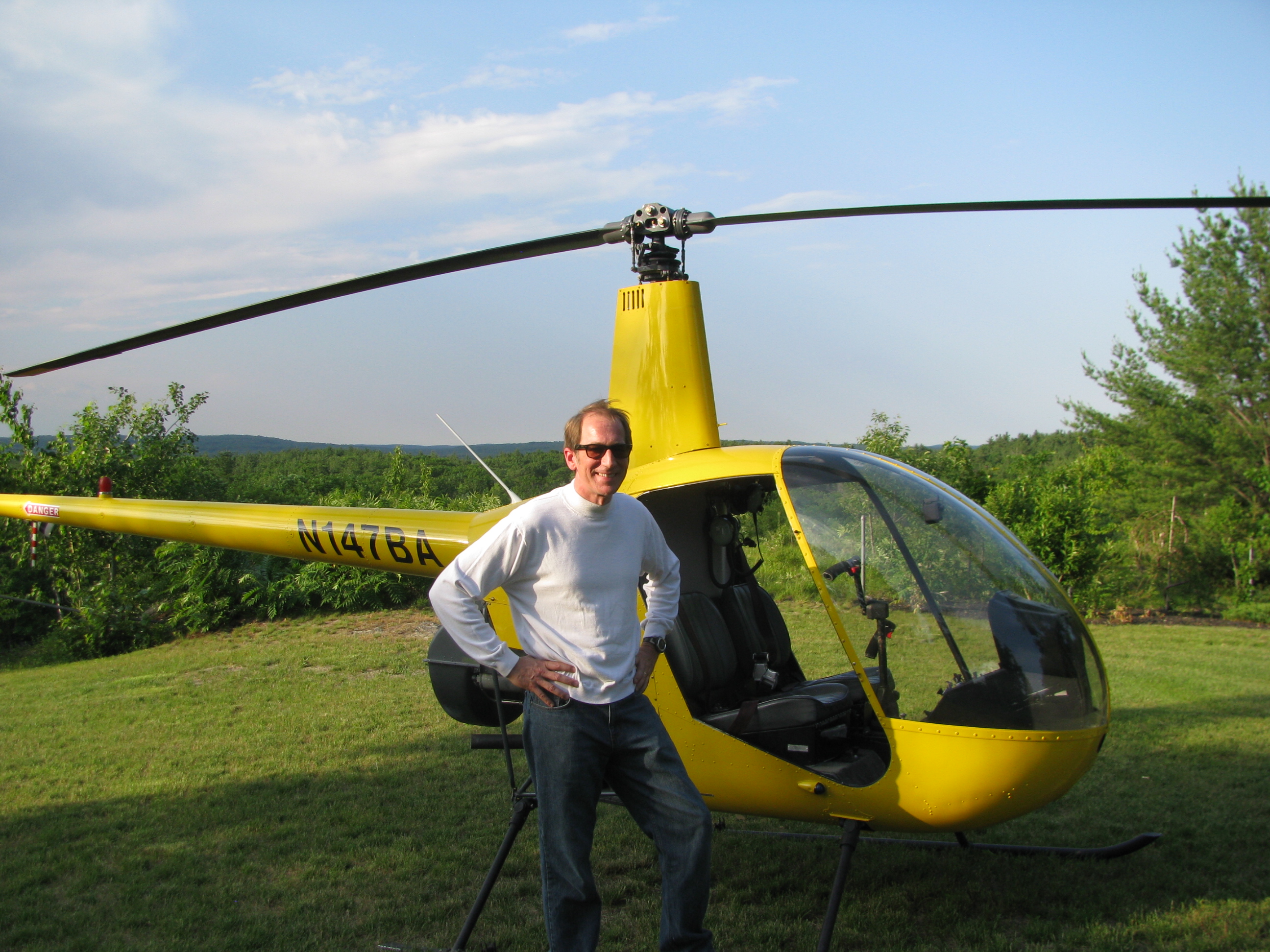

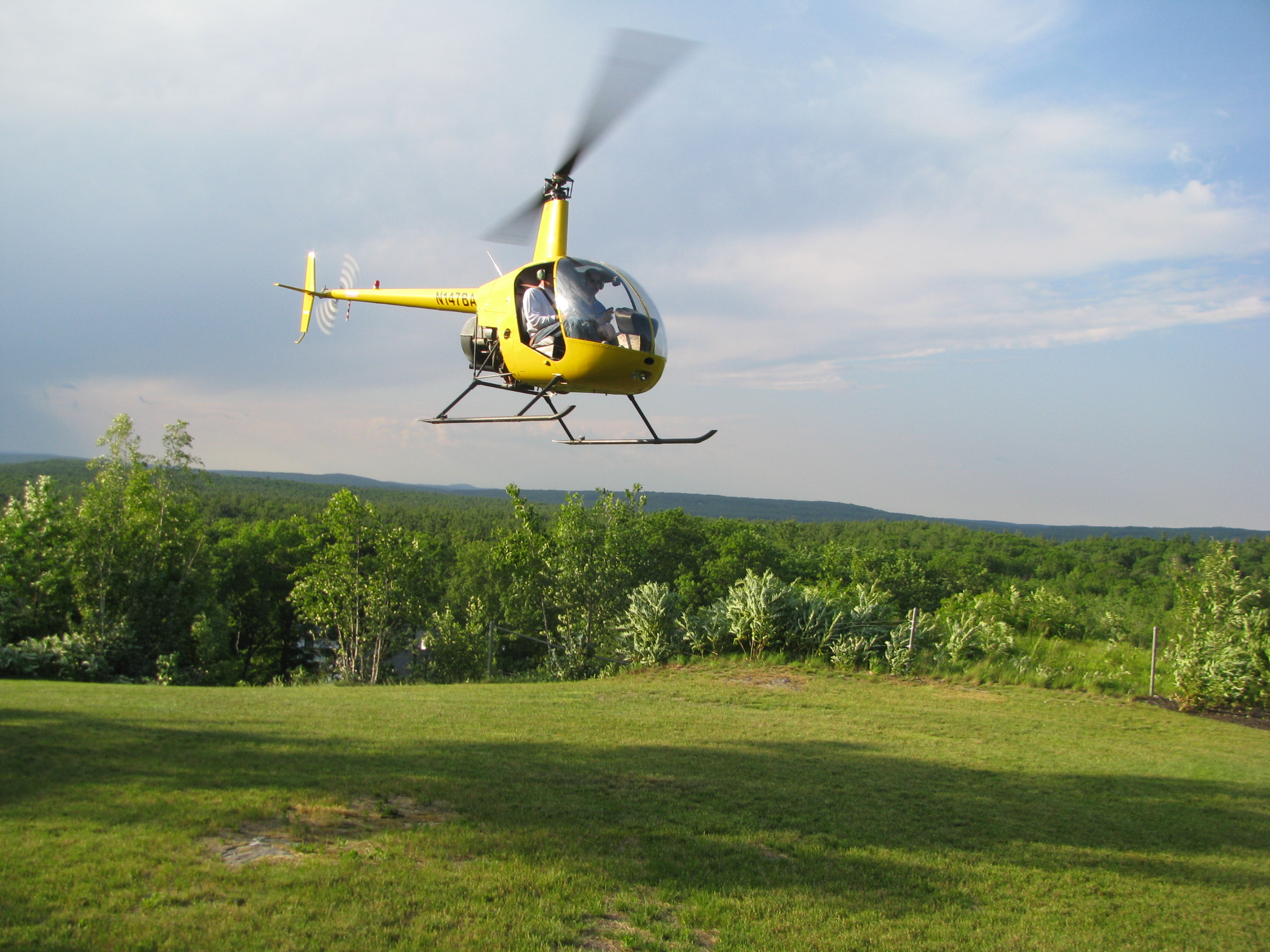
_________________________________________________________________________________
Getting closer. About 8 more hours of solos, a cross-country, then check-ride prep. Maybe another month. Better get cracking on the Helicycle.
More BodyWork
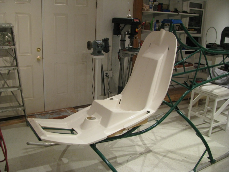
With the controls initially fit, it’s time to get back to mounting the seatpan and body shell. When I last left this task I had done all the fitting of the pan, and added some flox pads to fill the gaps between the pan and the metal tabs. They’re fit up pretty well and tomorrow I’ll drill the floorpan bolts.
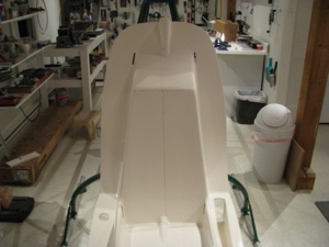
The pan pretty-well centered. The hump at the top is slightly offset to the right in this picture. This is because the mast will be slightly offset as well and the control rod presumably goes to the center of the mast.
Helicopter SOLO!!
Probably working against me was the fact that I watched the Robinson R22 safety seminar video on DVD the prior night. They go through the many ways that R22s fall out of the sky and how to get into and how to avoid unrecoverable situations. Pretty damn sobering and definitely forefront on my mind as I took the mighty R22 up on my own. All was fine, though and as with my airplane solo, the first couple patterns and landings were probably my smoothest to date.
Cool. Cool. Cool. 10 more hours of solo and 3 of checkride prep and we’ll be pretty darned close to the rating. More incentive to get cracking on that Helicycle. Let’s get back to building!!!
Training Restart
I decided to restart the training, but this time I would take a week off of work and schedule two sessions a day to make as rapid advancement as possible. I started last Sunday (the 17th), and finished my week today. I logged about another 11 hours, doubling my total time in the span of a week. A couple of days were washed out due to New England springtime weather.
To my surprise, the basics came back quickly. I felt like an idiot during the first pre-flight as I had forgotten where everything is - a bad sign. But, the muscle memory was still fundamentally intact. The first 30 seconds were hairy, but I could still almost hover.
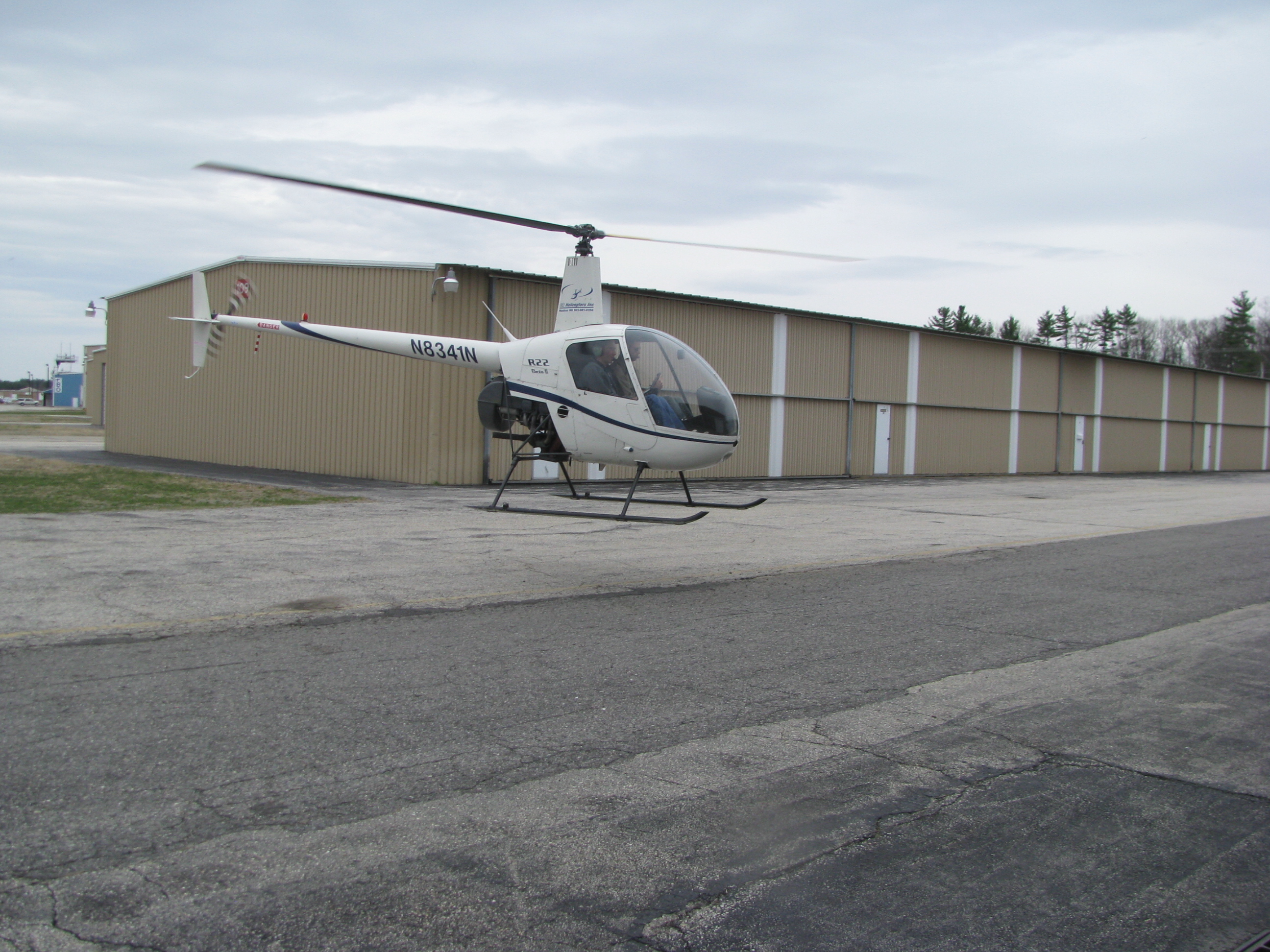
By the end of the week, I feel pretty OK about hovering, and there is some level of confidence that if my instructor Corey were to drop dead in the left seat, that I could continue the lesson and return the ship to C&R, insuring that his family got paid for the full lesson, without any bent metal on the ramp.
Autos are still not mastered. I can do one acceptably, but on the next one lose track of airspeed or RPM, or heading. It is not reflex yet, but still an intellectual process. Until the responses and control are semi-automatic, and the big three (RPM, airspeed, and position) are more in hand I would question my ability to complete one without balling up the machine. I am still having to THINK - RPM low, lower collective, OK, too high-raise it. Ooops, too much, back down. My responses are not fluid enough such that if I start chasing one parameter or the other, then we’re in for a roller-coaster ride.
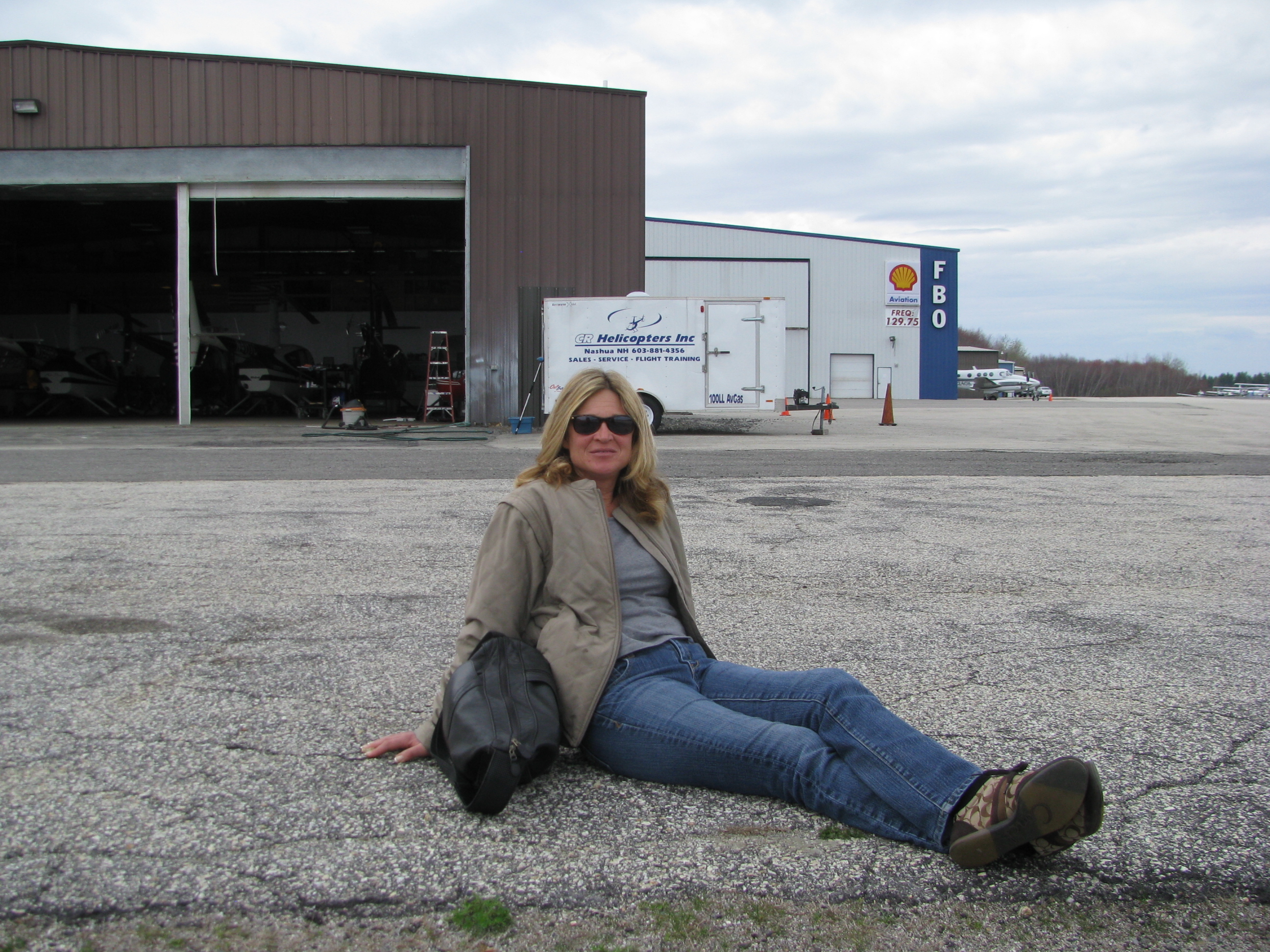
Lee came out to watch one day. She hid behind the trailer there when I started schwanging the mighty R22 all over the sky.
Still, comparing the start of the week to now is night and day. Whereas a wind gust during hover at the start would take 20 seconds to restabilize from, now it’s almost immediate. We’ve started to talk about the big solo. Maybe another 3 or 4 hours and we’ll be there. I want to feel much more confident about controlling the parameters in autos before we take that leap.
Here's a short video clip of a Platform Landing. Crappy Video quality from a distance. Just take it real slow
Control Rods
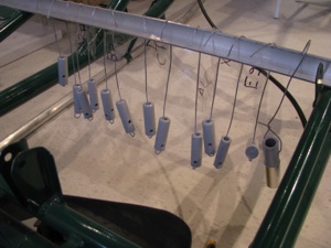
Here’s a really bad Idea I don’t recommend - dipping the end plugs in primer. Ever anal about corrosion, I thought this would be a good idea. Even though the primer is very thin, it’s enough to make screwing in the rod-end bearings very difficult. Two turns in and one back out, almost like retapping the plugs. Once cleaned out they’re fine, but I am sure it was hard on the threads.
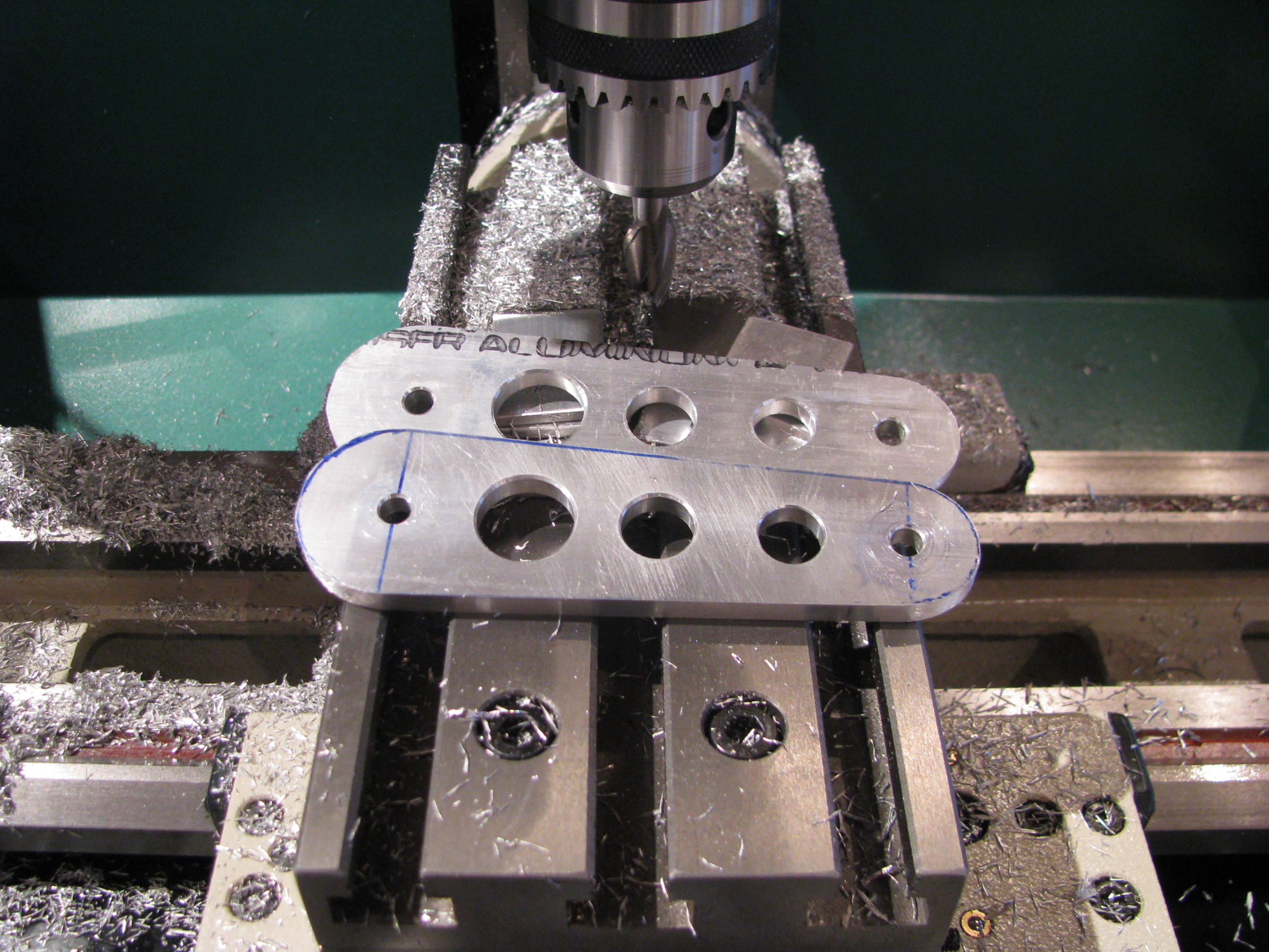
Another commercial for the Grizzly mill/drill. Bolt together the walking beams, bolt to the table at 3.5 degrees and mill away. Afterwards 20 seconds on the belt sander and done. Careful as the edges on milled parts are razor sharp.
All you machine shop nazis can rail on me for not using the proper collet on the mill, but changing is a pain and I took very small cuts. Of course I would switch over for more extensive jobs.
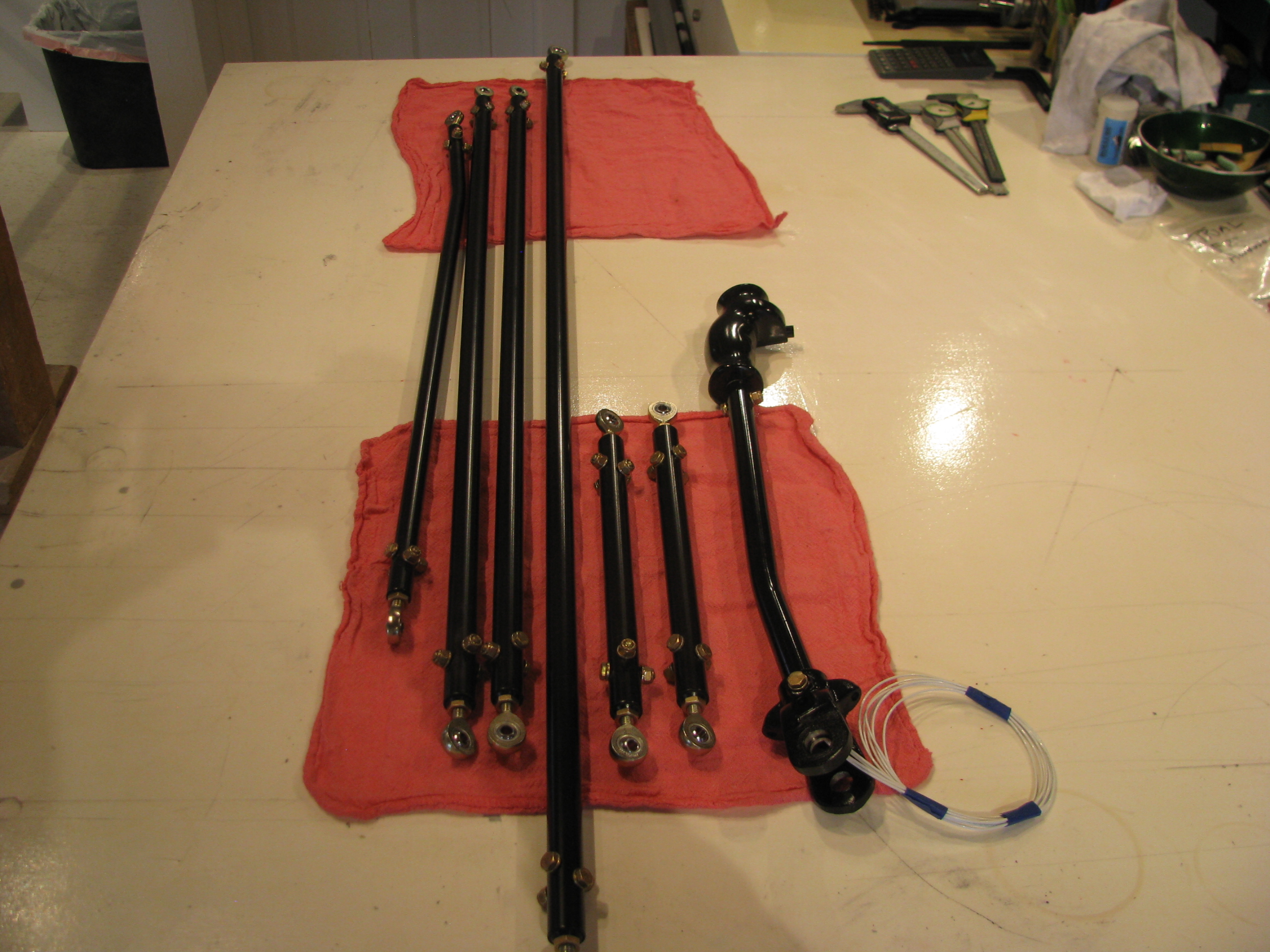
Parts starting to look finished - because they ARE finished. I know these will probably get dinged up during the continuous fitting/refitting, but the epoxy paint should be easy to touch up just before final assembly.
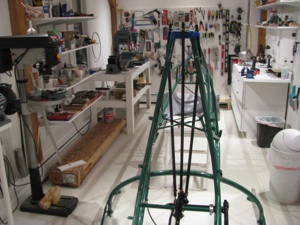
Cyclic assembly in ship with control rods preliminarily placed.
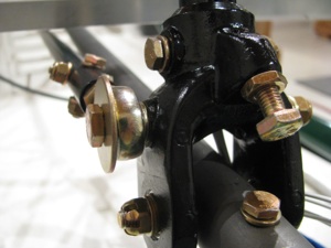
Front end of cyclic stick mounting.
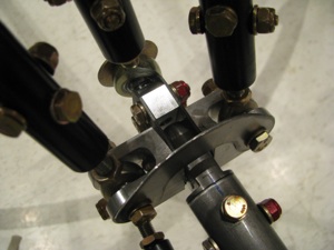
Top view of mixer and rods.
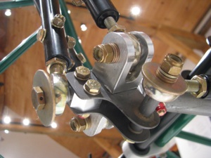
Bottom view of mixer. Lots more washers than really needed so I don’t bite into nylon on any of the lock nuts.
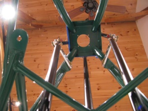
Looking up at walking beams. Obviously they are not set to the proper angle yet.
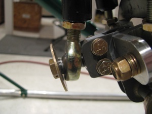
This is a clearance issue with the stick full forward - actually it limits the stick from going full forward. You can see the fore-aft rod end touching the mixer bracket. I could grind a little off the mixer, but I am going to wait until things are closer to being in rig to worry about clearances. The main thing is that it all fits and there is little or no slop at all in the controls and they all move cleanly. Very cool to see this come together. There is almost no friction in the system and BJ seems to indicate that a little friction is a good thing, so I will go back and reinvestigate.
Of course now it all comes back apart.
With the preliminary placement I can see the extent of the travel on the slider. Now I can go back and clean up and paint the cyclic control tube.
I just have one support call to make to Eagle, which will be my first. The mixer U-shaped aluminum wings are held together with an AN4 bolt (which looks to be a change from the machined bolt in the videos). Two washers are supplied - presumably one for under the head of the bolt and one for under the castellated nut. Well, with a washer under the nut there is not enough clearance for the rod end to move. Without the washer the nut rides right on the aluminum of the “wing”. That doesn’t seem right. Hmmm...
Cyclic Update
No major building activity this week due to work/travel/taxes.
Cyclic Controls
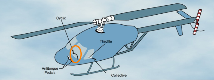
The Cyclic Controls direct fore/aft and lateral changes in force applied to the motion of the helicopter. This is probably the most complex part of the Helicycle design and as I have started to build it I am gaining appreciation for the elegant simplicity of the design employed. It’s hard to envision how it works together from pictures until you hold the parts in your hand and see the complex mixing of inputs performed. The cyclic control inputs and collective control inputs have to get mixed together before being applied to the direct rotor head controls.
Precise and careful manufacture of these subsystems will be undertaken to result in a smooth, slop-free response to operator input.
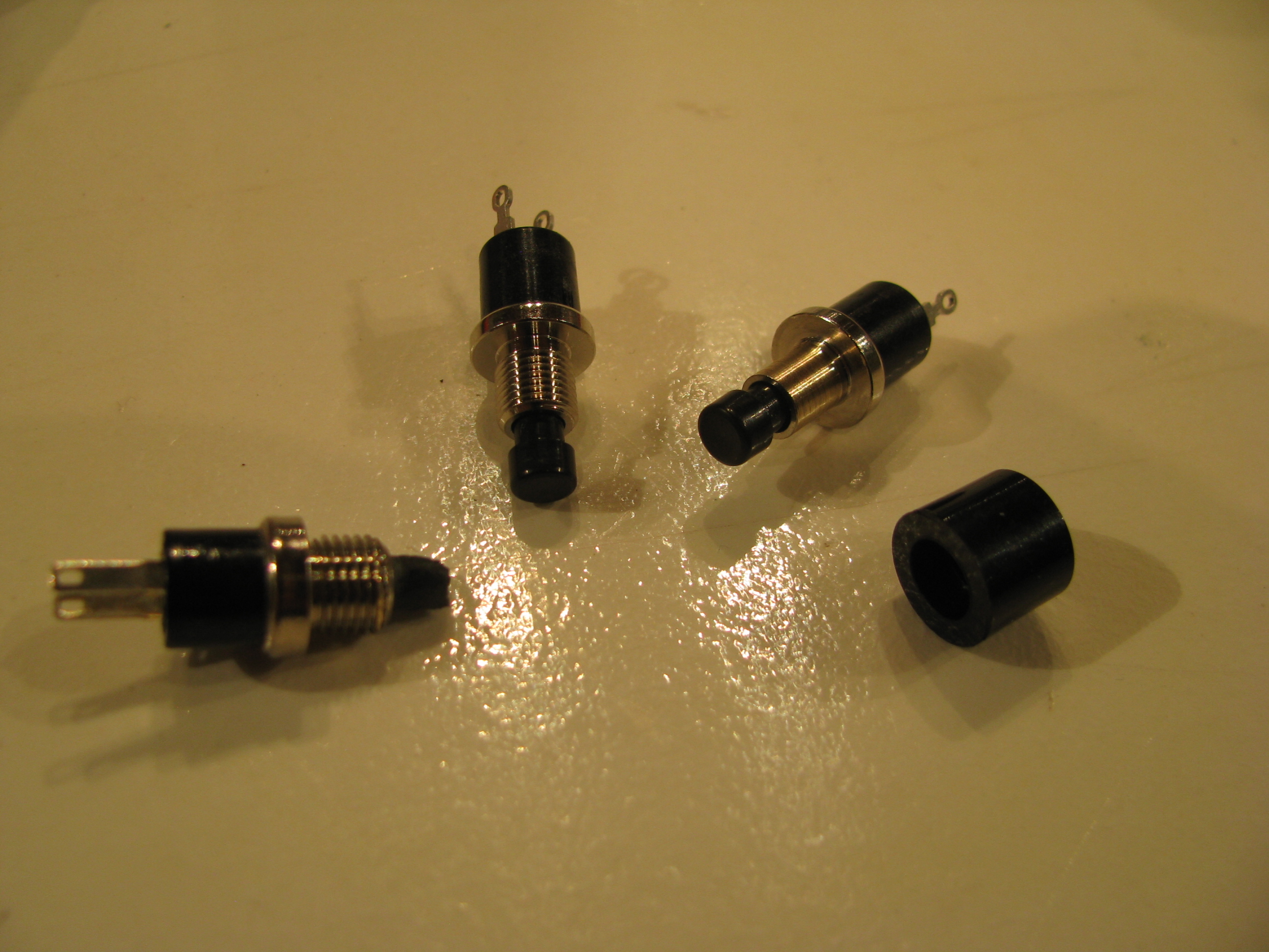
Of course having said that, the first thing I did was to break off the head of the Mic switch while trial fitting it to the handgrip. I got a couple of closest match replacements from Digikey (there are no visible vendor markings on the switch from the kit). The button head did not slide over the threads of the new switches, so I just lathed off the threads. The button head will get epoxied to the end of the new button switch.
Several hours shot finding replacements and reworking something that should have been quick.
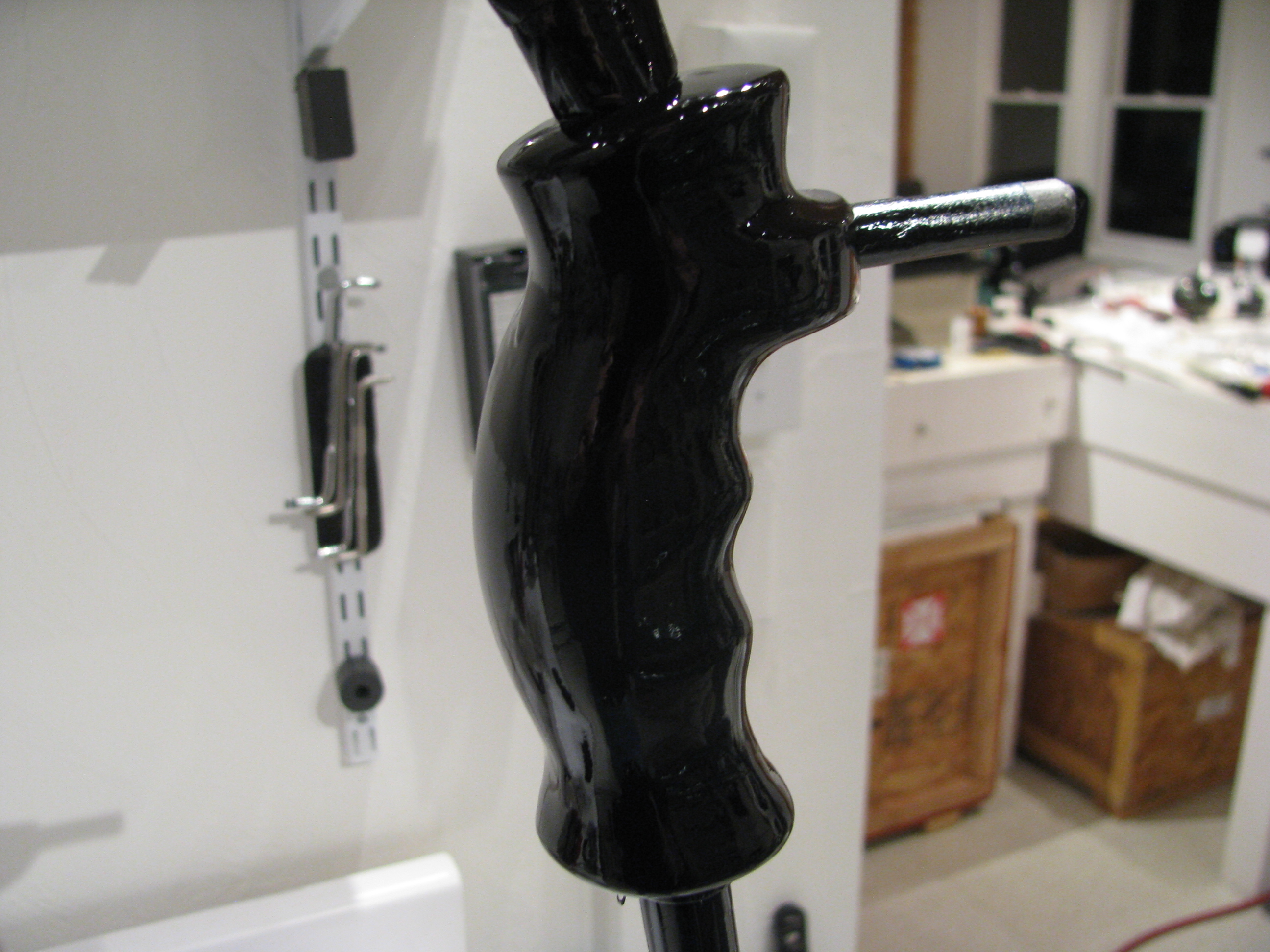
The grip provided seems fine for me. I know a lot of folks have replaced this with something more advanced, but using the top button for flip/flop on the radio, and the trigger for the Mic should be adequate for me.
Gotta remember to keep it simple or I will be building forever.
Some sanding and smoothing is required as the grip appears to be rough cast of an epoxy resin, then 6 coats of the VHT epoxy paint hopefully will prove durable.
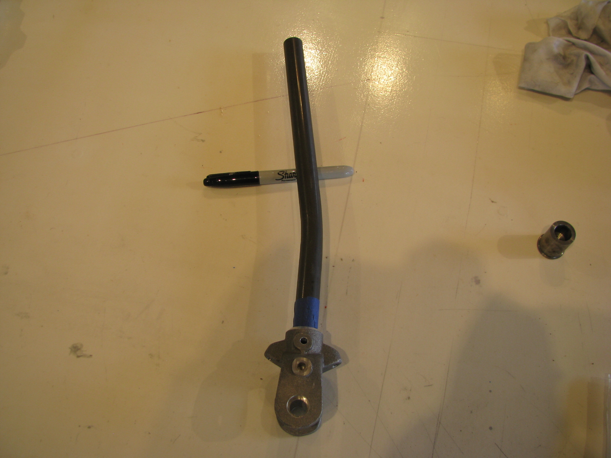
Cyclic stick drilled to the casting. I must say that I am amazed just how many custom castings are included in this kit.
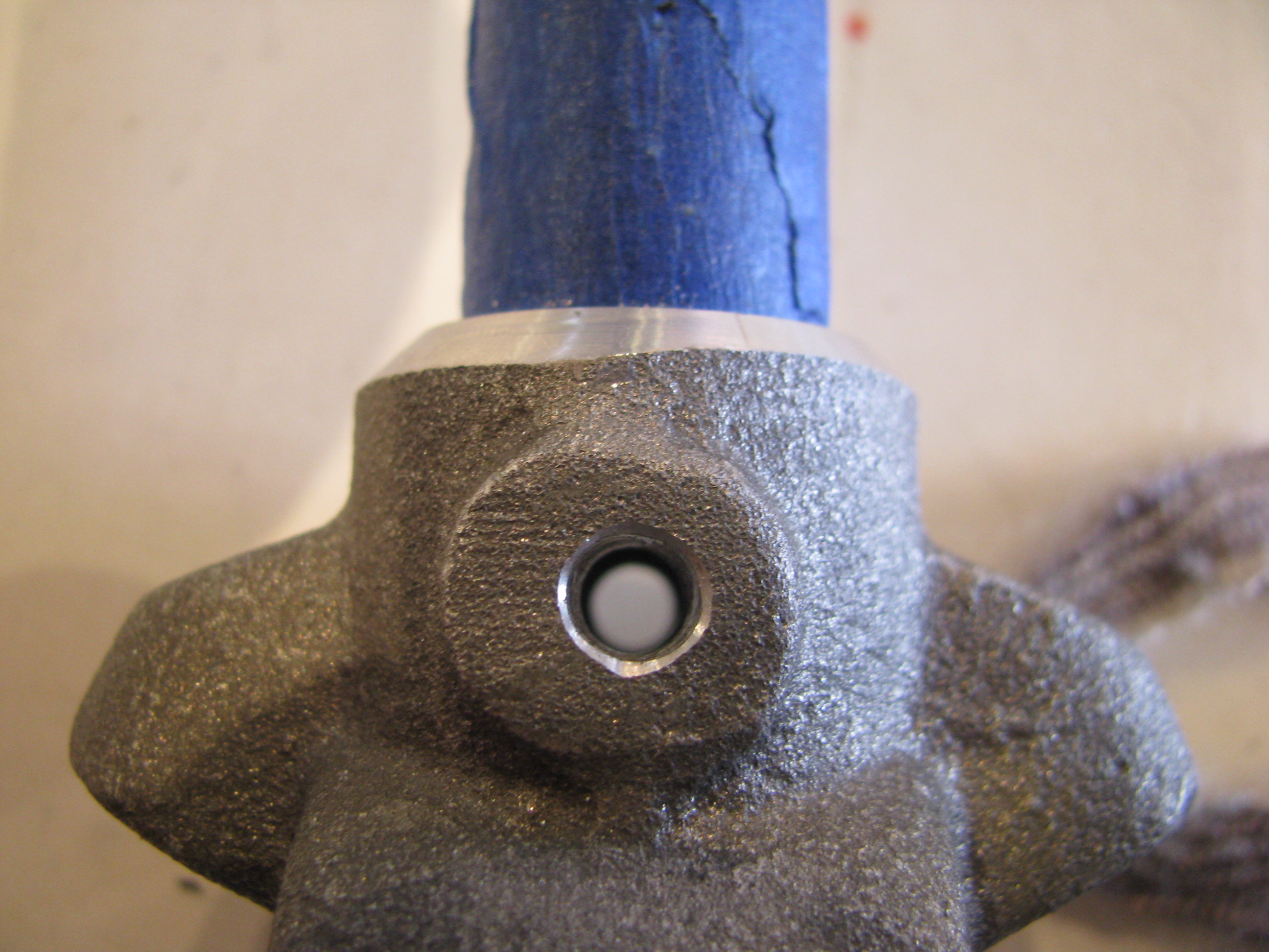
Another mistake. The bolt fit is kind of sloppy here, like the hole is maybe 1/64 too big. I don’t know whether I grabbed the wrong bit, or didn’t have the casting clamped well enough while drilling. I will first try a “close fit” aircraft bolt and then decide whether to bump up to an AN4 bolt.
Too bad, though. The hole is nice and square and centered. It’s always something.
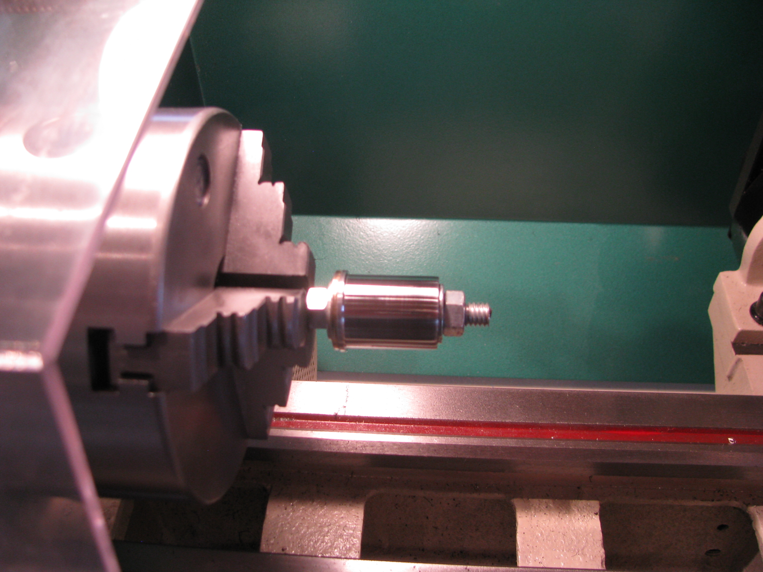
The steel plug for the front cyclic control tube was about 5-10 mils too large. Chucked it in the lathe and sanded it down a touch until it was very just very snug.
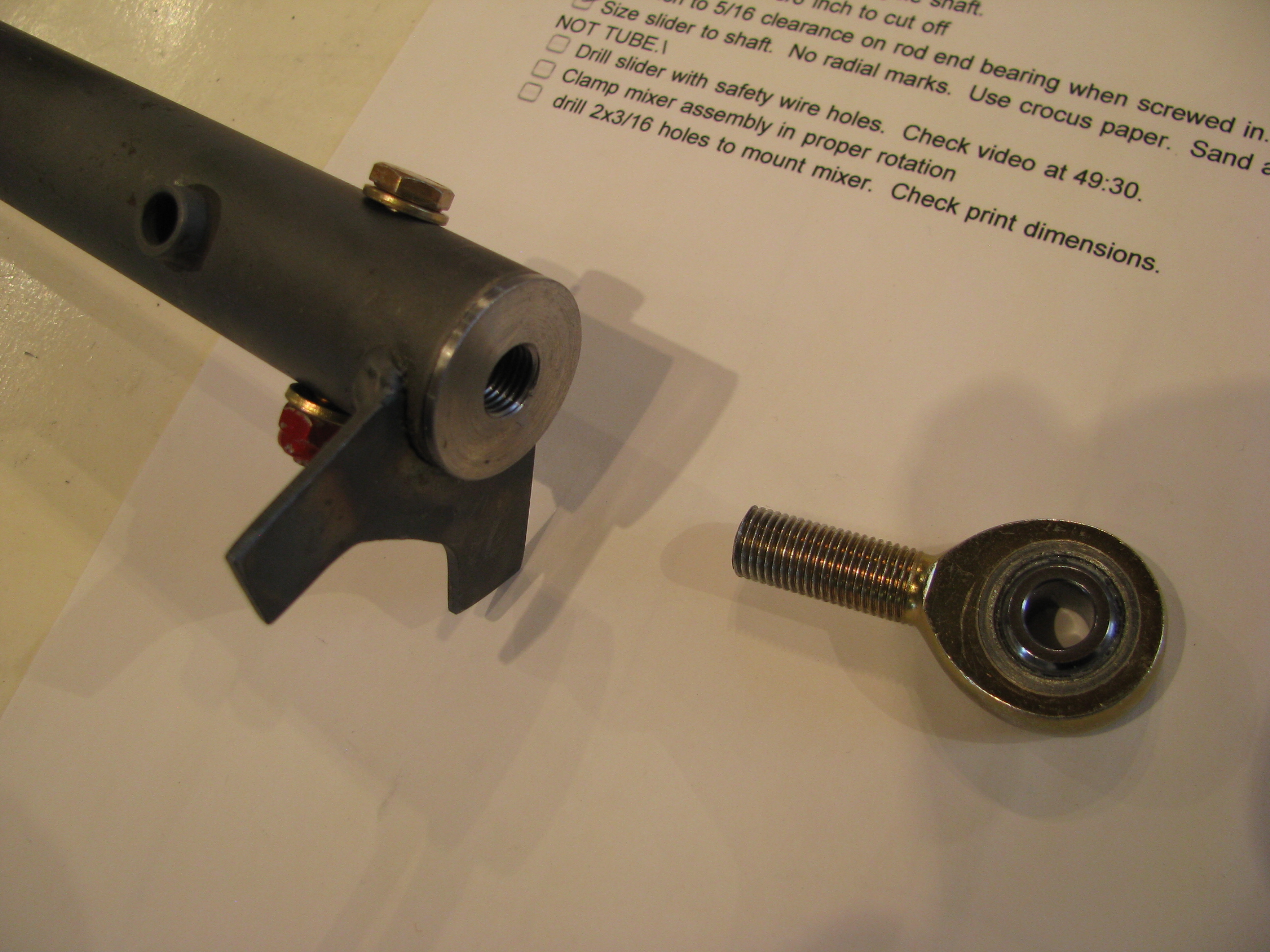
Had to sand the interior of the tube where the travel limit bracket was welded on. There were a few bumps where the tube deformed slightly while welding. Now the fit is snug, requiring just a light tap with a screwdriver handle to fit. Then I drilled the keeper bolt. Again, the mill/drill allows for a nice clean, square hole.
Cut 3/8 off the rod end and cleaned up the threads. The inner bush on the 5/16 rod end is very tight, even with additional grease. I may order some others if I can not get it to loosen up.
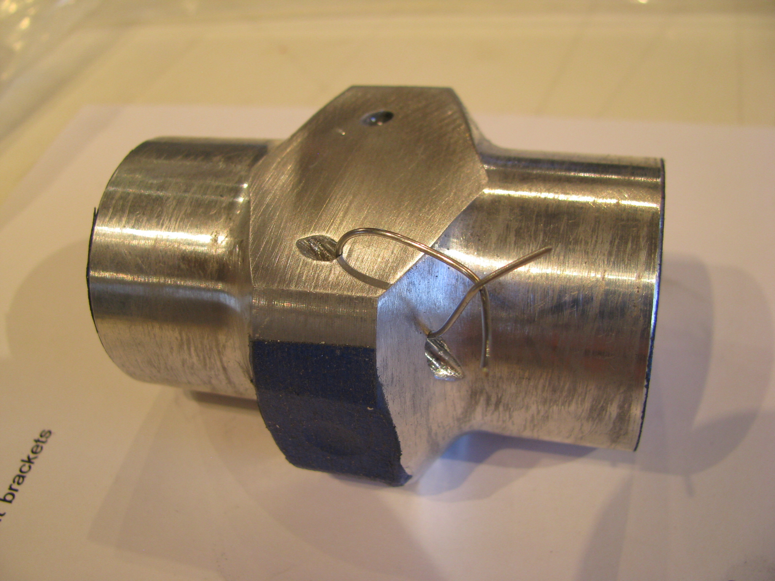
I agonized over how to make the holes for the safety wire/spring attach holes on the collective slider. After conjuring up many Rube Goldberg mill clamps, I ended up just free-handing it with a hand drill.
It’s a whacky angle since you definitely want to miss the interior features of the slider, but want the holes to pass through plenty of “meat” on the slider to stay strong. In both cases I was within 1/16 of my planned exit hole while drilling. Not bad. Start very small and work up very gradually, “steering” the smallest bit on the first cut.
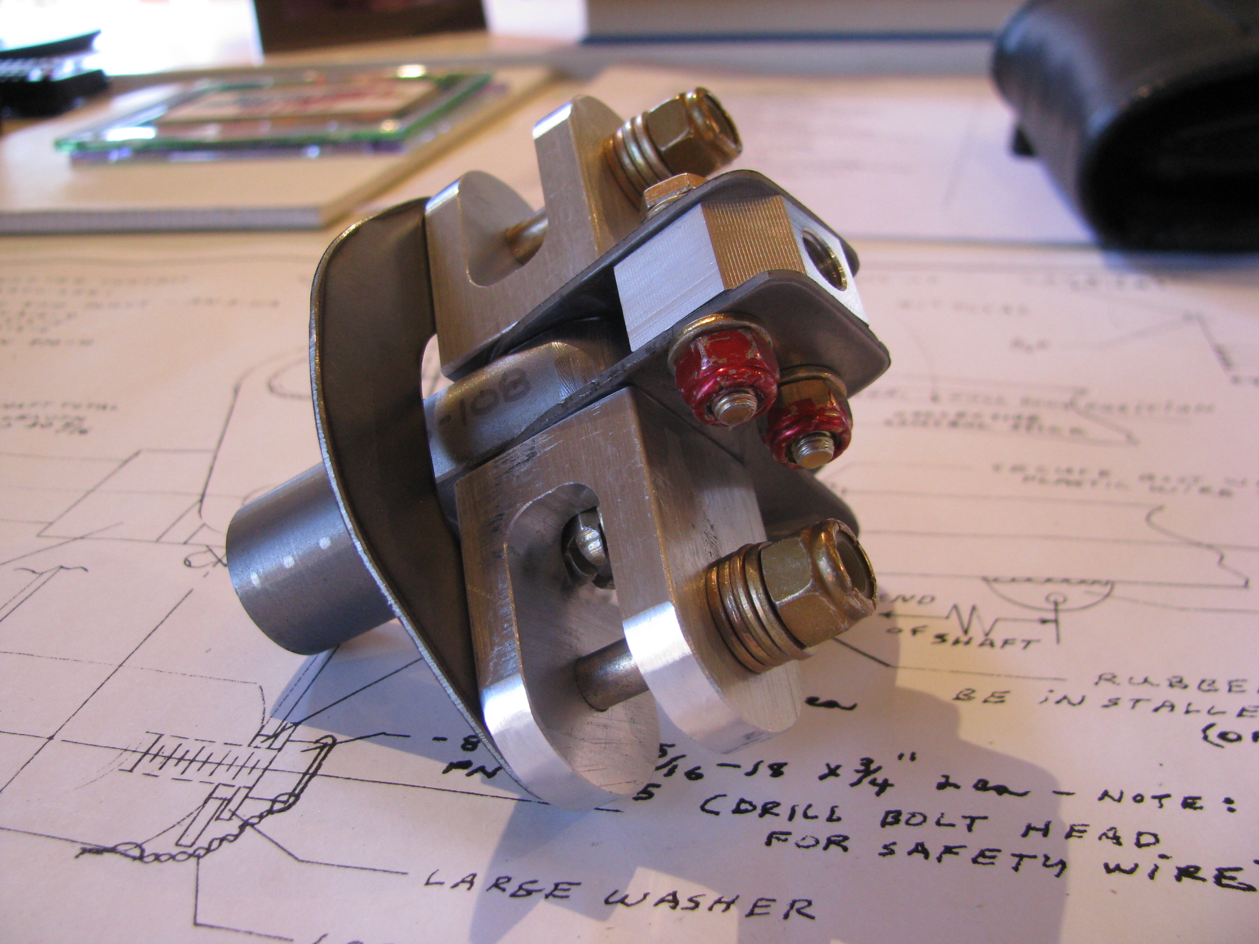
Trial fit-up of the mixer assembly. Neat little assembly. Sanding and grease really do affect the feel, so follow the tapes closely.
My kit was different than the tape and the plans in that there is an AN4 bolt between the U-shaped wings instead of the machined allen bolt that BJ refers to. It was in the correct bag and fits properly, so I am assuming this has been updated since then.
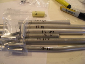
As a diversion, before drilling the mixer to the cyclic tube, I decided to knock off the control rod fabrication. I don’t know whether the kit came this way, or I did it to myself when we moved, but the rods were all taped together with cheap packing tape that left glue all over the rods.
It took about an hour with Goof-Off to clean them all up. That stuff was persistent. Goof-Off got its name because it will make you goofy if you breathe too much of it.
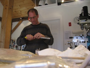
Obligatory, FAA-mandated picture of me deburring control rods. I engineered the shop lighting to highlight encroaching baldness. Works pretty well, eh?
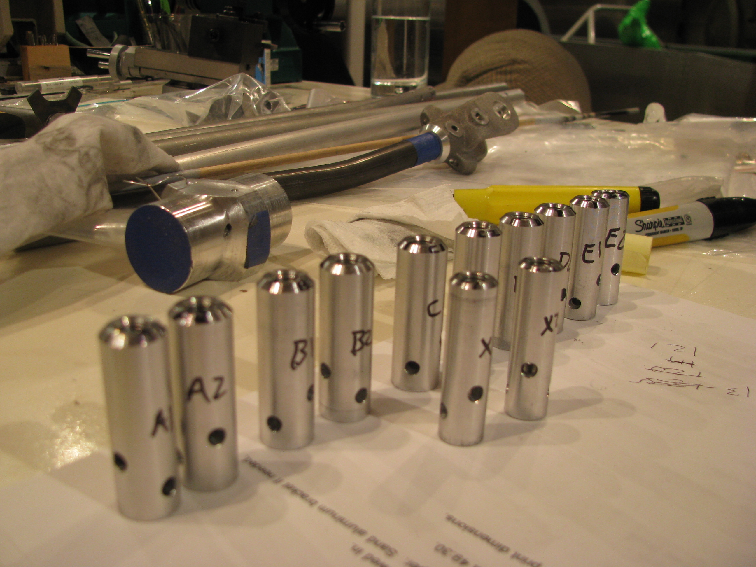
This was another one of those jobs that looks really quick, but took all afternoon and evening to clean up the rods, fit and drill the control rod end plugs into the rods.
Perhaps I was being overly anal about perfect 90 degree angles between the bolts, but that’s always been very visible to me and an indicator about the quality that may exist elsewhere on the ship. I did notice that even BJ’s bolts are not all perpendicular to each other on the construction videos.
I think it was Tim Drnec’s site showing how he welded the plugs and ground the rods so no bolts were visible at all. That’s really cool and I am sure it looks great, but a little over-the-top. I’ll live with the bolts. It’s my mantra now: “Follow the plans and finish the project. Modify later.”
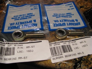
Not satisfied with the freedom of the end bearings I purchased another set from Aircraft Spruce. One is the teflon race insert (type T) and the other is the plain copper insert. The plastic insert rod end is as stiff as the the one supplied by the kit. The copper insert is as smooth as butter.
I am going to replace the ones in the kit (teflon insert) with plain copper inserts for smoothness of motion. Of course the ones I got were wrong. They are MM-5 and MM-5T. BJ uses XM-5 rod ends, which are heavier duty and larger. Crazy non-intuitive numbering system. The XM versions are not available at A.S. I had to order them from Wicks. The only possible downsides might be that the metal on metal requires periodic lubrication and might possibly cause some RF interference, but seeing as he used non-teflon rod-ends for all the smaller ones this can’t be a problem.
Collective Controls
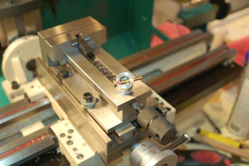 Having wrapped up most of the fin construction I jumped into the collective controls. This is a pretty straight up section with light fitting and machining. It gave me a chance to use the mill/drill/lathe. That thing is cool. Way more precise than anything I could achieve with a drill press alone.
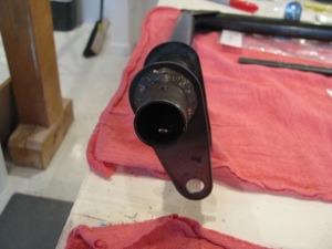
Start by drilling the end plug into the pivot end of the collective weldment. In the video BJ tells you to hammer a bolt into the aluminum plug. That didn’t quite sit right with me. So I lathed the bolt head down so it fit very snugly in the cap. The problem is that the “hammering” action is what would have held the bolt in the cap when the nut is tightened. Since the bolt is the pivot for the collective shaft it is not snugged down super tight. If it were to ever loosen up in there; a) There would be slop in the control, and b) it would be impossible to unscrew the nut off the end of the bolt.
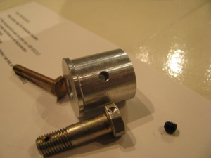
So I measured and drilled right at the point of the bolt head, tapped the plug for little 8-32x3/16 set screws that will sit inside the plug, and drilled a little into the bolt head. Same treatment on both sides. I’ll install the bolt, and loctite the set screws. That bolt isn’t moving.
Of course doing this with just a drill press would be a pain, but the repeatability of the mill/drill allow the operation to be repeated easily from a fixed reference point.
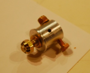
The completed plug assembly.
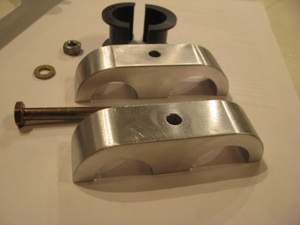
The collective is held in two places. The first is the pivot plug/bolt previously described, and the second is this aluminum construction. Two pieces of aluminum are supplied cut from bar stock. The corners must be radiused, which is no simple trick since they’re about an inch thick.
First the angle grinder, then the big belt sander and vixen file, then the little belt sander and sandpaper. This operation takes a lot longer than you ever would imagine.
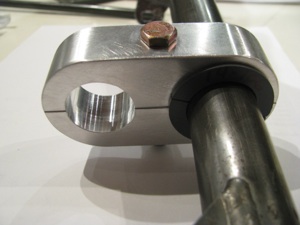
The result is worth it, though. There is something very satisfying about shaping aluminum from rough into beautiful. If I elect to paint this the finish is ready to prime. If not, I’ll give it a bit of a polish and clear coat, but since it’s buried pretty deeply in the structure I’ll probably not invest the time.
I cannot find the supplied throttle grip in the parts bags, so I suspect it did not find it ‘s way to me when I purchased the kit. I ordered an aftermarket Harley Davidson throttle grip. The 1-1/8” OD throttle grip shaft matches the throttle handgrip on certain model Harleys (49 to 73, I believe). Plenty to choose from out there of all sizes and prices.
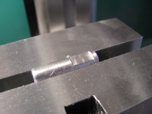
BJ tells you to 5-minute epoxy a length of 5/16 bolt into the end of the throttle twist shaft for the set bolt to “bite” into. Since I have to justify the expense of all this equipment, I milled a little flat onto the bolt section, just because it felt like the right thing to do. Instead of 5-minute, I JB Welded the slug into the end of the shaft after the hole had been drilled and positioned.
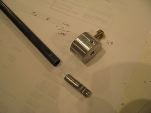
The slug, the shaft, and the collar that links the throttle twist shaft to the potentiometer shaft.
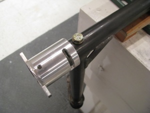
Potentiometer holder insert and bolted into place. This is actually a fairly complex machined part for such a simple function.
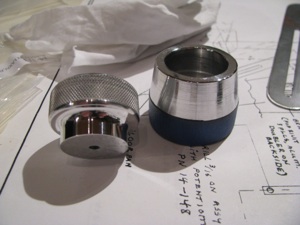
About 15 minutes of sanding and polishing were all it took to shine up the collective and throttle friction knobs. Mother’s Mag polish hasn’t failed me yet. Flitz seems to be recommended highly, but since I have two cans Mother’s, I am going to use it up first. I did mask off the knurled sections since the black polishing residue would probably be a pain to get out of there.
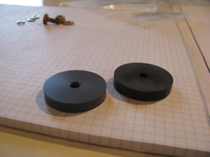
My parts bags only had a single plastic friction washer for the Collective Friction Assembly. The prints show one on either side of the collective friction slider bar, so I made one up from some plastic stock I had on hand. I think it’s phenolic. It feels similar in texture to the provided part. I am learning the lathe. Diameter is easy. Facing is easy. Parting and finishing the second side is not so easy on a part this thin. Parted with a hacksaw blade (it’s plastic), and was just able to get it in the chuck enough to face the second side. The tool was very close to the jaws of the chuck while facing.
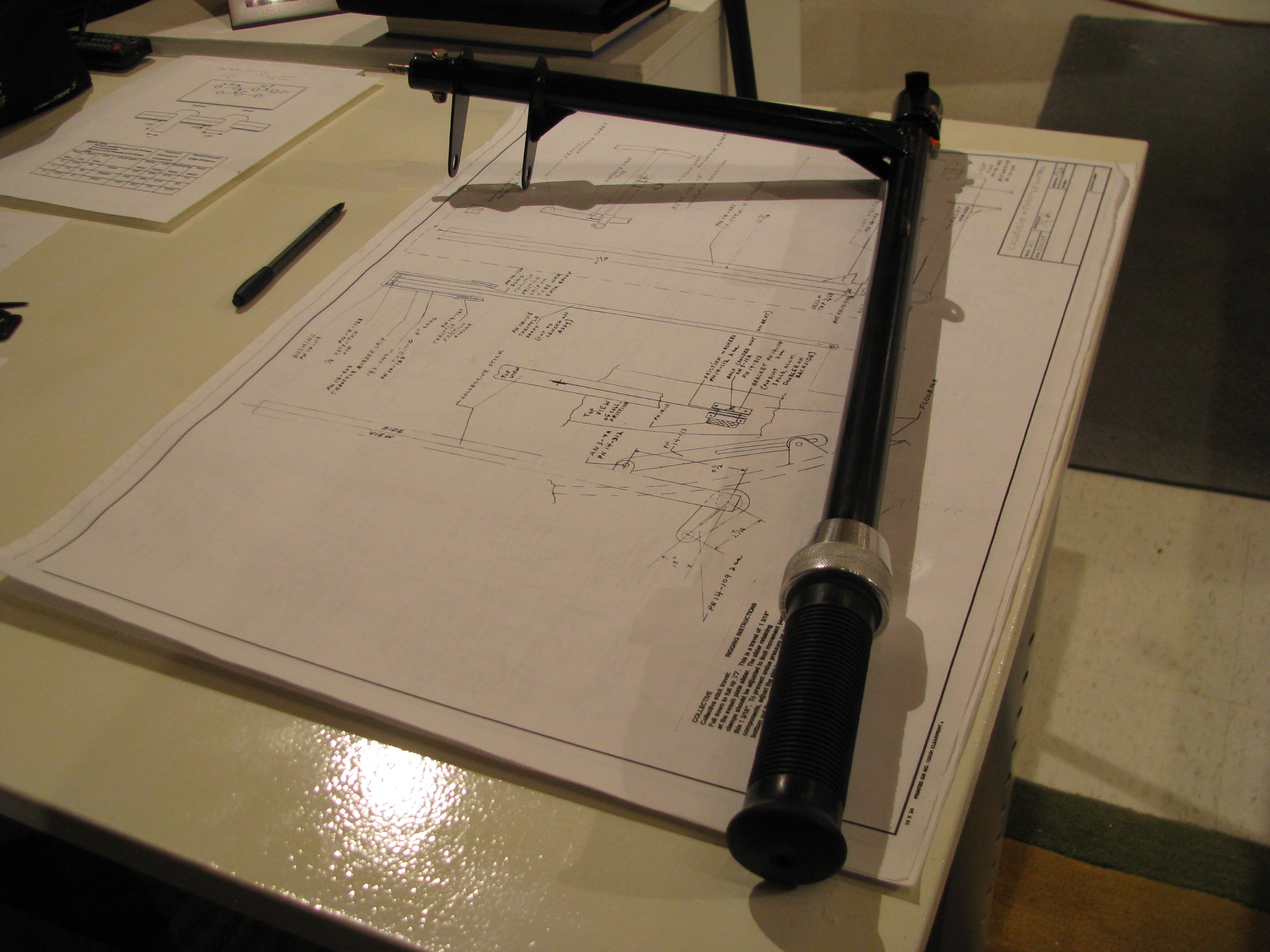
The completed throttle/collective assembly ready for installation into the ship. After experimenting with a few different grips, I ended up with one I bought just like the one BJ provides in the kit. It’s a Harley OEM-type throttle grip. None of the others I bought seemed appropriate for a Helicopter.
A light sandblast with 220 grit media to remove surface corrosion from the tube assembly and VHT single-part epoxy paint. Seems like good stuff as long as you let it cure for the many days specified before knocking it around.
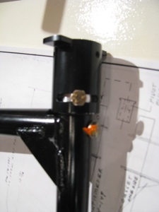
The potentiometer holder final bolted in place (obviously not the throttle pot linkage, though). Anywhere I “final” assemble a bolt and torque it to spec I use a little torque seal, not just as a movement indicator, but as a reminder to myself.
I can’t count the number of times I have let something sit for a week and then can’t remember if I completed this little operation or that. Any/all reminders help my advancing memory.
Finished Vertical Fin
Here’s little trick I read about elsewhere and modified a bit. To locate the exact, precise centerline of the steel spar under the fin I got these little powerful half inch round neodymium magnets. They naturally seek the spar centerline. Just prior to the rivet location, make a little “puddle” of Sharpie ink (or machinist's ink if you have it) and “push” the magnet through the puddle across the rivet line using a piece of aluminum.
Invariably the spar is not precisely on the measured and marked centerline. Using this trick the magnet pushes a line of ink and gives you the exact drill point. This one is toward the end of the fin and is off the measured line by about 1/16th of an inch.
Had I just drilled on the drawn spar line the rivet would have been slightly off center of the spar and a dimple would have resulted when the rivet drew things together and canted .
Here are the pieces coming together for the final time before riveting. You can see where I drilled out the lower rivets of the lower section so the curved tube would fit through without damaging the thin skin.
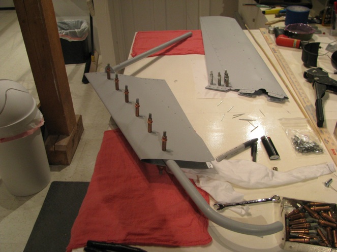
Fin Fabrication Start
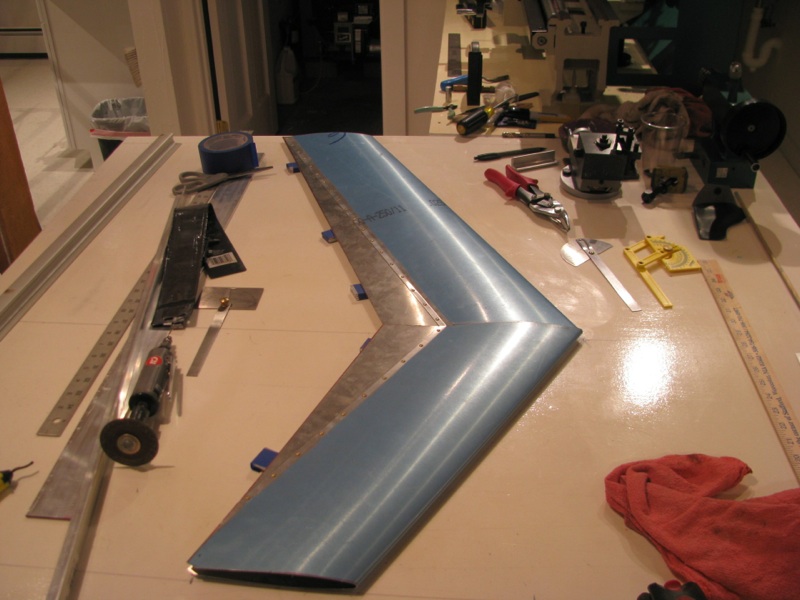
The fins use a prefabricated airfoil section that has to be cut per the plan, then fit to the steel tube spar. Cutting to shape was no problem, but I committed my first helicopter part butchery on the lower section. The tube spar has a curved lower section. In jamming it through the airfoil section I made a faint crease in the very thin aluminum skin. What I should have done is drill out the lower rivets to allow for easier fitting and riveted it back together on final assembly at the end. Oh well. Apparently I am not the first to have done this.
A replacement fin has been ordered, and surprisingly has arrived within a week. The box it came in also contained a turbine. Hooray!!! I have been pestering Eagle for almost the last year asking about my turbine. The answer was also “two more weeks”. Well pester-no-more. I have no immediate use for it, but I feel so much better having all the major helicopter pieces in my possession. No matter what happens to Eagle - not that I think anything will - I will be able to complete my machine.
Pedal Fitting
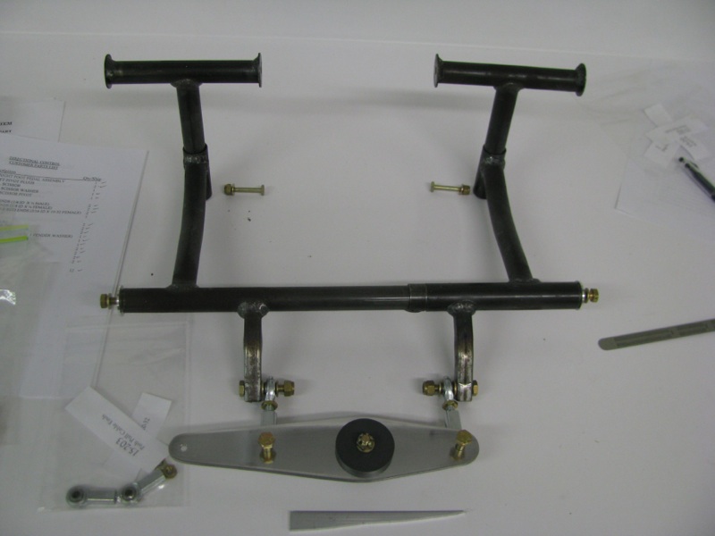
The directional pedals are a fairly straightforward sub-assembly, so it was an easy thing to work on to get back in the swing of helicopter work. I cut the walking beam and tried my hand at polishing. Aluminum takes on a wonderful shine with a bit of work.
These photos are as much for my own benefit as for any reader that may (or probably won’t) read this. Once fitted things get disassembled and will need to get back together properly.
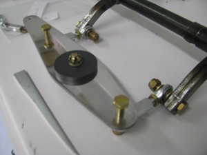
A little technique carried over from the RV building is to take a handful of nuts and drill out the nylon lock plastic. These can be used for preliminary assembly and will have the exact size of the final item. I mark all those trial nuts with red nail polish to make sure they will not find their way into the final assemblies.
I have read a number of builder logs that have replaced the aluminum pedal bearing plugs with a more suitable material since aluminum on steel is not the best long-term idea. I may do so eventually as well. One thing I learned in my years of abortive aircraft building is that I should build per the plans and modify later - otherwise it’s likely I will never ever finish in the first place.
It took a lot of fiddling, but I was finally able to achieve the pedal and cable travel specs called in the prints. Hopefully this will be duplicatable on final assembly.
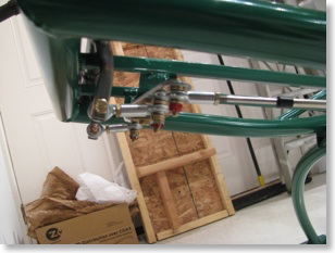
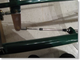
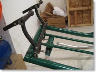
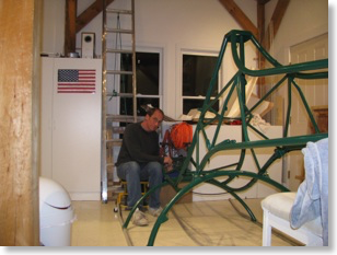
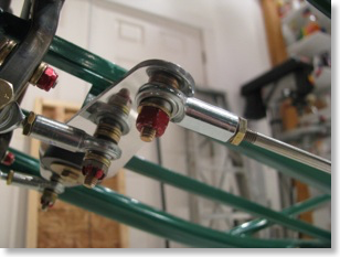
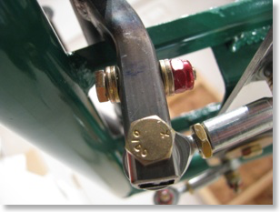
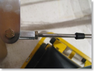
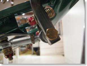
Moving & Restarting
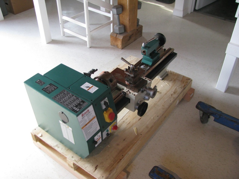 It had to happen that as soon as I acquired the Helicycle and bought a lathe we ended up selling the old house. After 2 years on the market and a bunch of jerking around we finally accepted an offer (for a fraction of our original asking price, of course).
 One of the motivators in settling for a lower price is that we had found a new place on top of a hill, 360 views, and a large outbuilding which has turned into the new airplane factory.
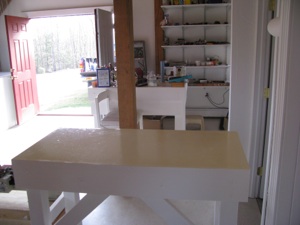
I started by gutting the outbuilding, tearing out the walls and retiling the floors. All the wiring had to be redone, drywalling, and finishing. White white white. It looks like an operating theater now.
I built worktables, installed shelving, and redid the lighting. Between the move, and the refitting of the shop, I did not get anything done on the aircraft until well into fall.
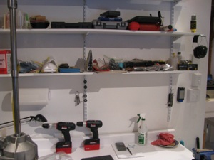
It looked huge right up until the airplane and helicopter fuselage and frame were brought in. Now it’s quite snug.
My personal vow is that we will NOT move again until the airplane and helicopter are finished. What a PITA to move that stuff.
Lots of shelves and countertop space.
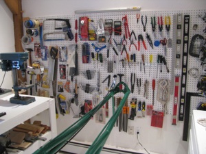
New pegboards gave a chance to reorganize the tools. It’s nice to have them all neat and logical again.
I was pretty lost for a couple of months during the move with everything in boxes. If I needed a wire stripper it was an hour-long treasure hunt through boxes.
Much, much happier now knowing where everything is.
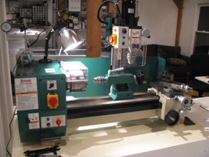
Just prior to selling the house (and the REAL trigger for getting a good offer), was my taking receipt of a Grizzly G0516 Mill/Lathe. This is a couple of steps up from a little mini lathe.
Yes, yes, I’ve read all the reviews saying a 3-in-1 is not as good as separate machines, but I have limited space, and don’t see myself using it every day.
I have played around and made some small items so far. Fun. Looks like it will more than meet my limited needs.
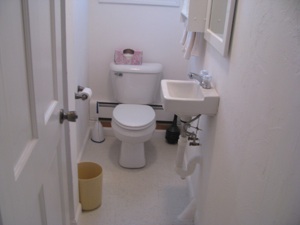
One of the more luxurious aspects of the new shop is having a bathroom and shower. A small electric water heater caps it.
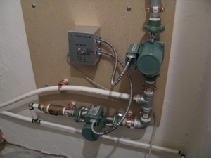
Unfortunately the water run to the shop was buried less than 12 inches from the surface underground. The biggest single project I undertook was to dig up the old water run, and dig a new trench (by hand) 36-48 inches deep. 137 feet long. There were two spots where ledge prevented a deep lay. The pipes are about 8 inches deep at those points.
I ran a conduit with 2 x1”insulated PEX pipes. In the house there is a loop manifold.
In the shop I put two circulator pumps. One just loops water through the feed and return. The second circulator loops the feed through the hot water heater and back out the return.
I can program the timer to loop hot water 1 minute out of 10 or 1 minute out of 20, depending on how cold it is out.
If I get super motivated someday I will add a thermocouple to the return and optimize so I am not
paying as much to heat the ground.
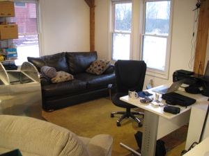
One section of the shop is set up as an office/lounge with a desk, couch, comfy chair, laptop, internet and a TV.
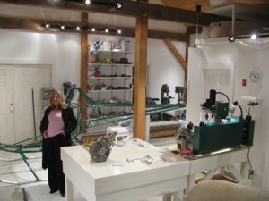
Comfy shop, beautiful wife. Should be a good place to work and play.
Flox Pads
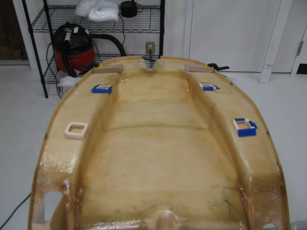
I laid up a strip of fiberglass on the right hand side between the tabs. The pan currently rests on the tab welds, and I don't want to grind those or the flat part of the pan, so I will build up the area between the tabs slightly. Two strips of cloth was not enough, so I will probably build a little dam and pour a thin strip of flox (resin and cotton fibers) between the tab locations and sand it down until the pan rests on it.
I did this little section first to get reacquainted with fiberglass. It's been a while. Warm the resin! My can was maybe 65 degrees when I poured it and it glooped out like toothpaste. I had to heat the cup in a pan of warm water until it flowed like honey before starting. I remember that now and have re-set-up my box with a lightbulb to keep the resin warm on fiberglass days. Unlike most RV builders I actually like working with fiberglass. It's kinda magic to take chemicals and floppy cloth and build something remarkably strong out of it.
I made little U-shaped dams out of urethane foam to contain the flox "pads" for the seatpan mounting tabs. The foam was tacked down with 5-minute epoxy, then the flox was mixed and poured into the cavity. Flox is much thicker than resin, but still thin enough to flow, so you have to either pour it flat or contain it.
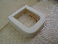
On the left side curve (second tab down from the top, the distance is quite large. Instead of bending the tab a ton, which will draw the hole closer to the curve of the seatback, I will just build this one up taller and leave the tab only slightly tweaked to be flat with it.
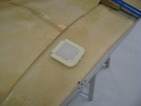
Flox poured. In all cases I built the pads to be taller than needed so I can then sand them down. The foam will then get sanded to a nice radius and a layer of thin cloth laid up over the top of the whole thing.
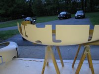
I cut the scribed slots in the fuselage halves. Overall the fiberglass looked sound, and there are just a couple of locations on the edges where the gelcoat got thick and there is a little separation between fiberglass layers. Those will get sanded out and a new strip of cloth or two added since they're right on the joggle lip mating surface and need to be strong. Gelcoat is non-structural. The interior is quite sloppy. There are a lot of little hairs and some places where resin pooled up. I will sand those down and probably be able to take down enough to compensate for the weight of my flox pads. Net sum zero on weight gain for my mods.
I may be critical of certain things on this kit that are less than perfect, but overall I am impressed by what you get for the money here. I have no idea how Eagle can do this for the price of the kit.
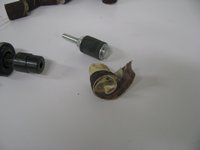
The sanding drums for the die grinder are quite remarkable. They work great, right up until you catch the end on a lip or edge, then they explode, sounding like a gunshot going off and just disappear at high speed across the room. I've used this thing a lot and have never done that before, then I had it happen twice in ten minutes. Guess that means I'm getting sloppy and it's time to stop for the day.
Eye, ear, and dust protection are a must.
More Pan Fitting
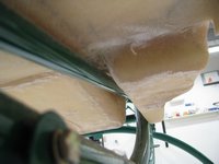
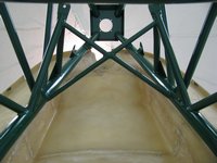
Of course with some prints and a manual this would all be immediately evident. Instead you have to watch the same video over and over (drives my daughter nuts) to try to glean this.
Perhaps I just got spoiled with the Van's RV8A kit, which has great documentation by comparison. Now don't get me wrong, I am immensely impressed with the Helicycle kit so far. For the money spent, the frame, fiberglass, materials, and especially the machined parts appear to be of very high quality. The budget was spent on machining parts and tooling, and not on documentation.
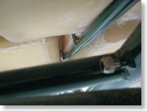
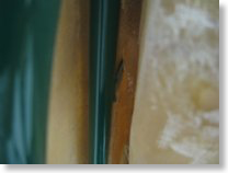
The source of the misalignment are the vertical tabs next to the collective pocket. Looks like those have to be bent inward a hair.
One thing I do not like about the fiberglass is the appearance of the bottom surface. The whitish areas almost appear as if they weren't wetted out fully. When I get my epoxy I will probably brush on a thin coat to "seal" them. It doesn't look to be a structural issue, but certainly a cosmetic one that bothers me.
I looked ahead in the videos to the next step, which is the instrument pod mounting. I did not get the 12 inch long 3/8" drill bit when I picked up the kit, so I'll probably have to order one. I must admit that the "jiggle and elongate the holes" approach does not excite me. I'm pretty sure there must be some sort of clamping arrangement that can be constructed to more precisely achieve the same effect. I don't like the idea of elongating the holes, then tightening the bolts to hold it all in place. Once again, I will consult Tim Drnec's and Juan R's sites to see what they did. Those two guys really set a high bar when it comes to fastidiousness and quality workmanship. While I want a straight, true, clean, and reliable ship, I doubt that I will be able to meet their standards of excellence.
Rotor Head Arrives
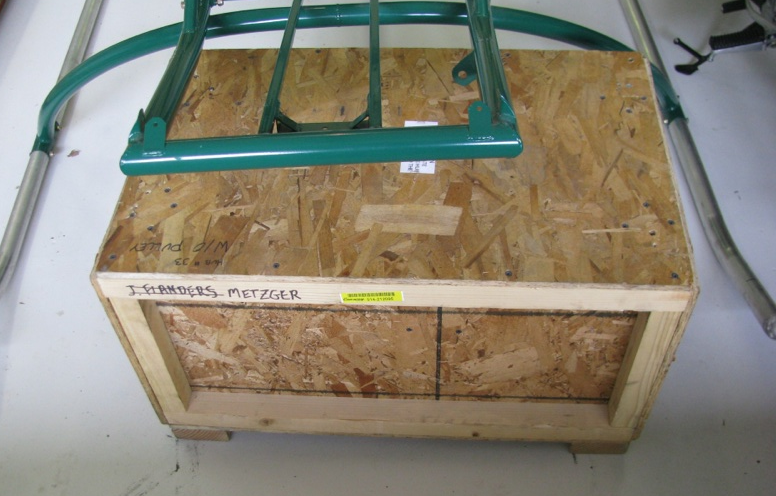 Unpack the rotor head crate. As I stated earlier, since the kit was purchased from another builder, most of the elements have been delivered or are on their way. The rotor blades and rotor head shipments arrived last week. The only item left is the turbine.
 Everything was in great condition. EXCEPT for a slit-like gash in the rotor head crate that I somehow missed when the delivery truck was here. I opened the rotor BLADE crate to inspect it since I figured that was the one subject to the most possible shipping damage being larger.
WRONG. It was perfect. The smaller box is the one with the gash. It looks like a forklift tine, or something, was sliced into the crate. There is a tiny nick on the rotor head that I will have to dress, but hopefully it is OK. That piece is absolutely gorgeously machined. My camera had trouble focusing on the nick since the piece is so shiny.
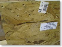
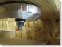
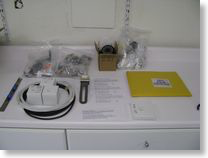
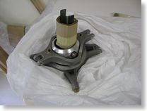
Pan Fitting
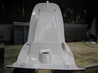
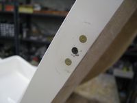
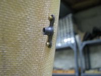
As can be seen below, a fair amount of material has to come off both sides of the front of the footwells to fit down between the two front frame tubes. The fiberglass is at least doubled up here around the bends, so hopefully the strength is not compromised too much. We shall see as this will probably be a high stress area in getting in and out of the ship.
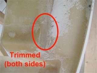
As can be seen below, a fair amount of material has to come off both sides of the front of the footwells to fit down between the two front frame tubes. The fiberglass is at least doubled up here around the bends, so hopefully the strength is not compromised too much. We shall see as this will probably be a high stress area in getting in and out of the ship.
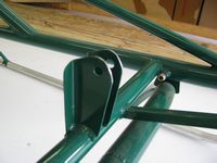
Shown here is the grinding I had to do on the control bracket to clear the seat pan as specified in the video. Still seems to be plenty of meat between the hole and the ground edge. There's about 1/16 of an inch clearance between it and the seat pan. I DO plan on repainting the frame after all the preliminaries are done just prior to final assembly. Green - what was he thinking?
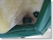
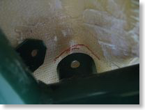
Here are the control tube mount tab locations when the front of the pan is flush against the mounting tabs. Pretty tight. I am going to shave a little off the inside of the round to fit the front plane of the pan down a hair lower.
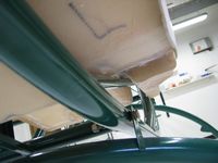
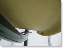
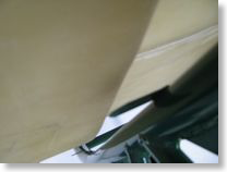
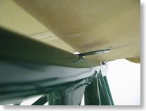
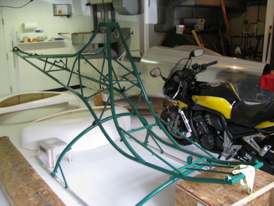
Project Start
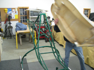
Busy month. I finished refurbishing the garage, which is quite full at this point with the RV8A still in there, and all the fittings for the new project. I painted every surface white, and discovered something really cool. Periodically Lowe's has some killer deals on pre-fabricated bathroom cabinets. A couple of sections of those with a pre-fab countertop makes a nice workbench/storage cabinet. I am sure it is not precisely, perfectly flat, but pretty darned close. I will shim and do all critical tolerance work on my flush surface in the downstairs shop. The project is all here. I received the rotor blades from Eagle. The only thing left from them is the turbine itself, which I have no immediate need for anyway, so delivery, though promised "soon" is not super critical to me at this time.
Harbor Freight is my friend. I picked up a bunch of odds & ends I didn't already have; a 4" die grinder, more clamps, a 1" belt sander, blades, etc...
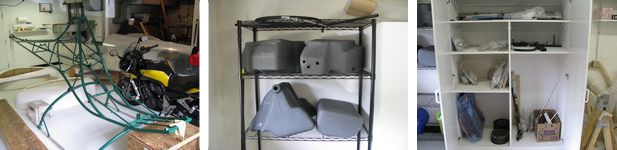
Real Project Work!! I first started by checking over all the Group 1 work done by the previous kit owner. He got as far as mounting the frame on the skids, then starting to clean up the seat pan. The gear mounting looks acceptable. His holes are square and I should just need to replace the hardware with known good and properly sized items at final assembly. Though his work seems acceptable, his color choices were not. Green?!? That'll change for sure. The seat cushions are also a hideous purple/pink combo which will probably end up getting replaced at some point.