
CollectiveControls
Controls Installed
03/03/14 00:19 Filed in: All
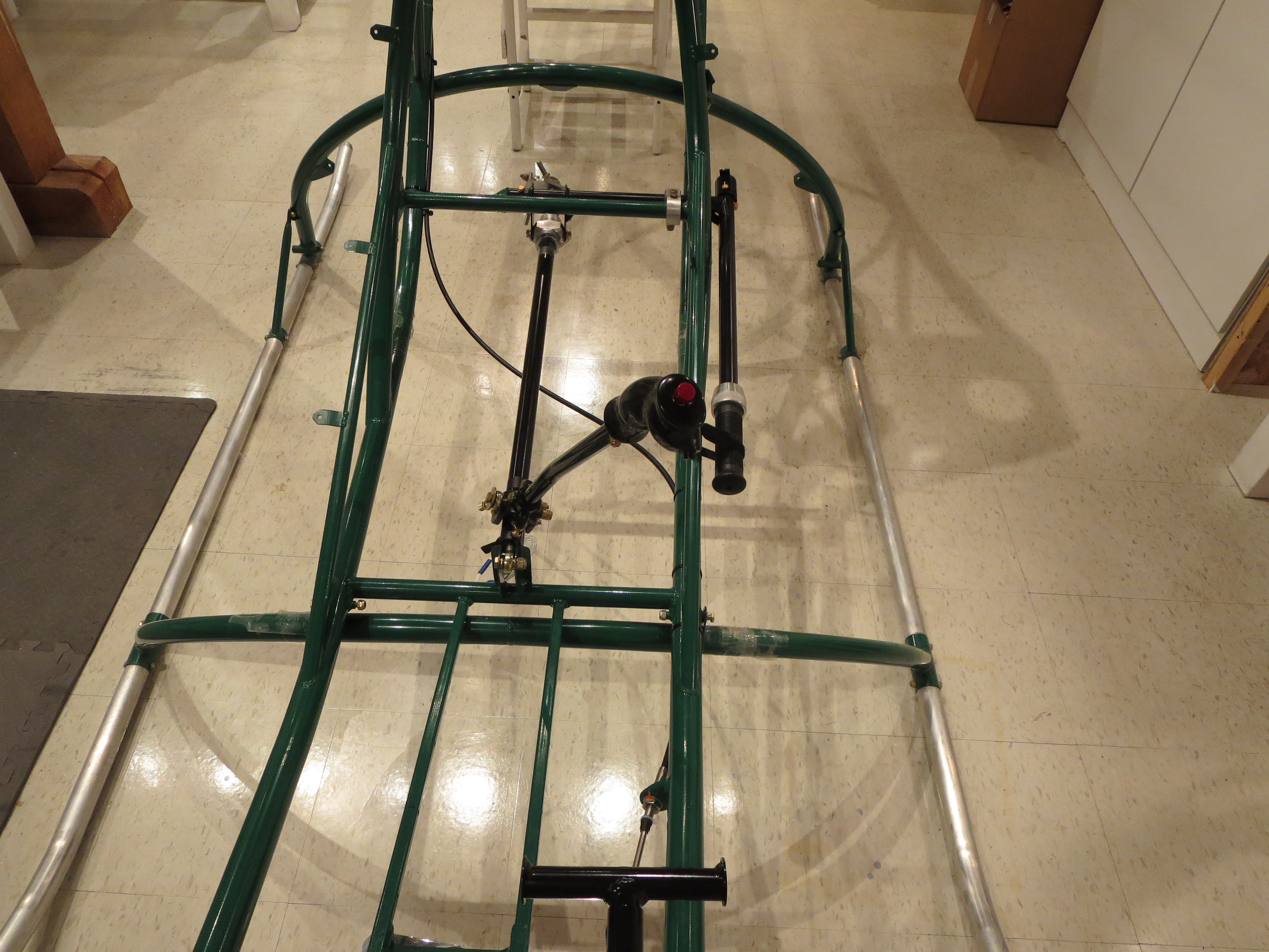
Installed the collective controls and cyclic controls in the ship for the "final" time.
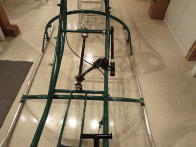

Everything is torqued and safety wired. I put a dot of torque seal on the nuts after final installation. Since all the pieces had been pre-fit, it was very straightforward. The only annoyance was that one of the Grade8 bolts I had purchased pre-drilled really wasn't drilled all the way through. It demonstrated that the Loctite sets up very quickly. The portion in the threads was already gummy after only an hour or so after installation.

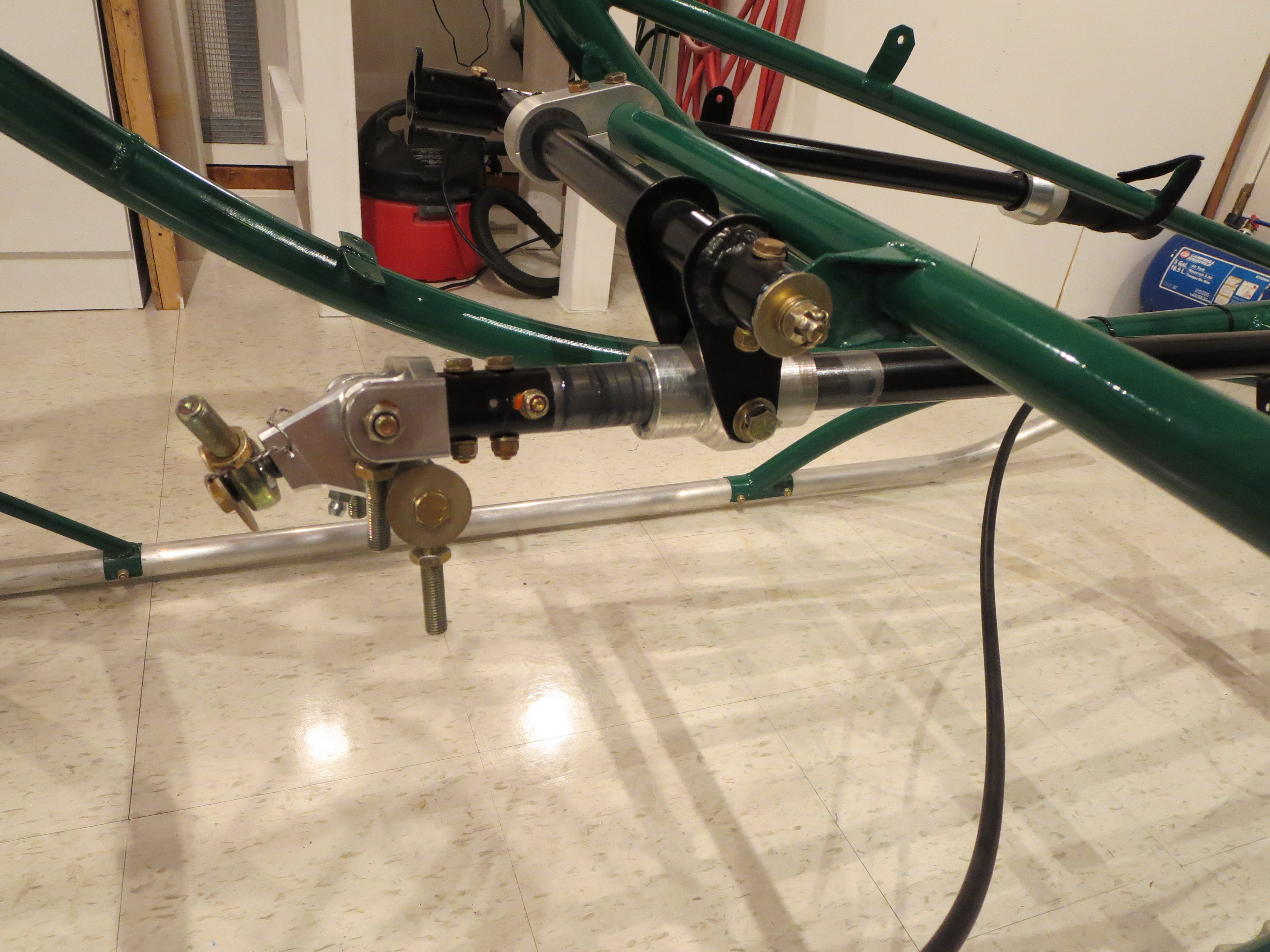
The control stick has almost no resistance fore and aft due to the bearings in the stick, but a slight amount in the left right since it is turning the cyclic shaft in the slider. It;s all greased well, and there is no breakout force, per se. We'll see how it all feels when the rest of the control arms and fittings are installed.
Everything is torqued and safety wired. I put a dot of torque seal on the nuts after final installation. Since all the pieces had been pre-fit, it was very straightforward. The only annoyance was that one of the Grade8 bolts I had purchased pre-drilled really wasn't drilled all the way through. It demonstrated that the Loctite sets up very quickly. The portion in the threads was already gummy after only an hour or so after installation.
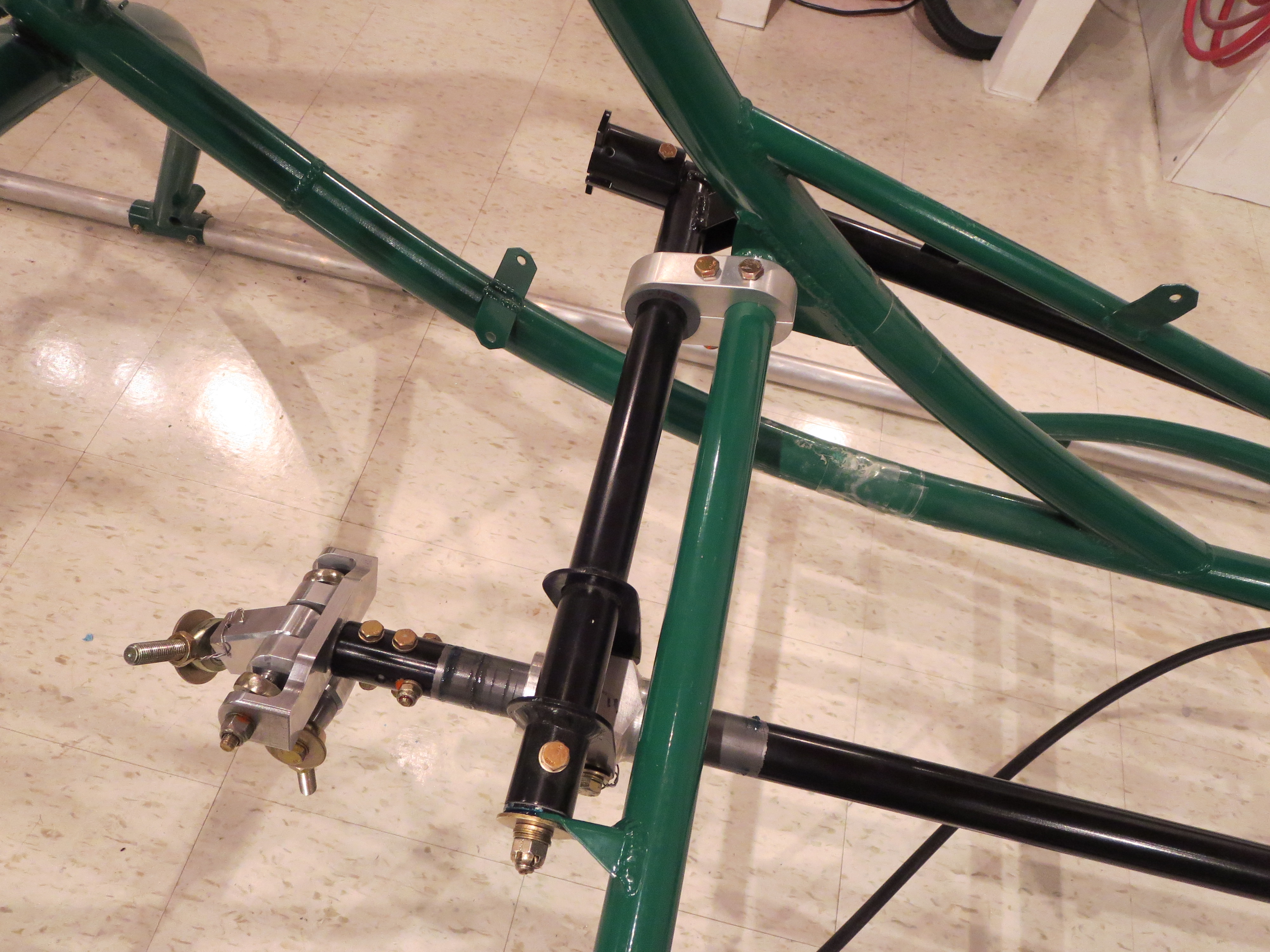
The control stick has almost no resistance fore and aft due to the bearings in the stick, but a slight amount in the left right since it is turning the cyclic shaft in the slider. It;s all greased well, and there is no breakout force, per se. We'll see how it all feels when the rest of the control arms and fittings are installed.
Mixer Refit
02/16/14 22:54 Filed in: All
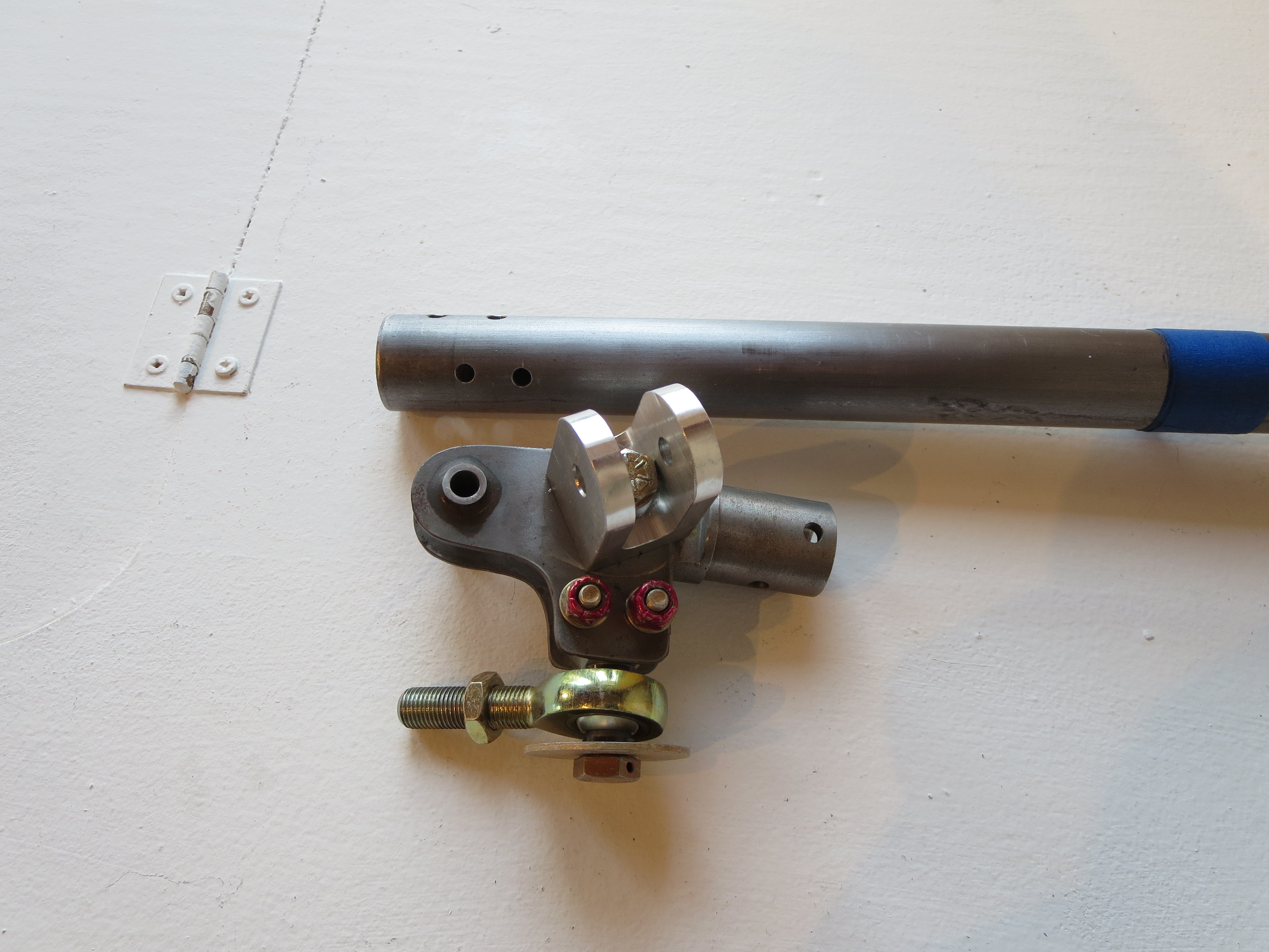
The original mixer (partially disassembled) looks fairly primitive next to the nicely CNC machined parts of the new one. I was never a huge fan of the single bolt in the center holding the "wings" together.
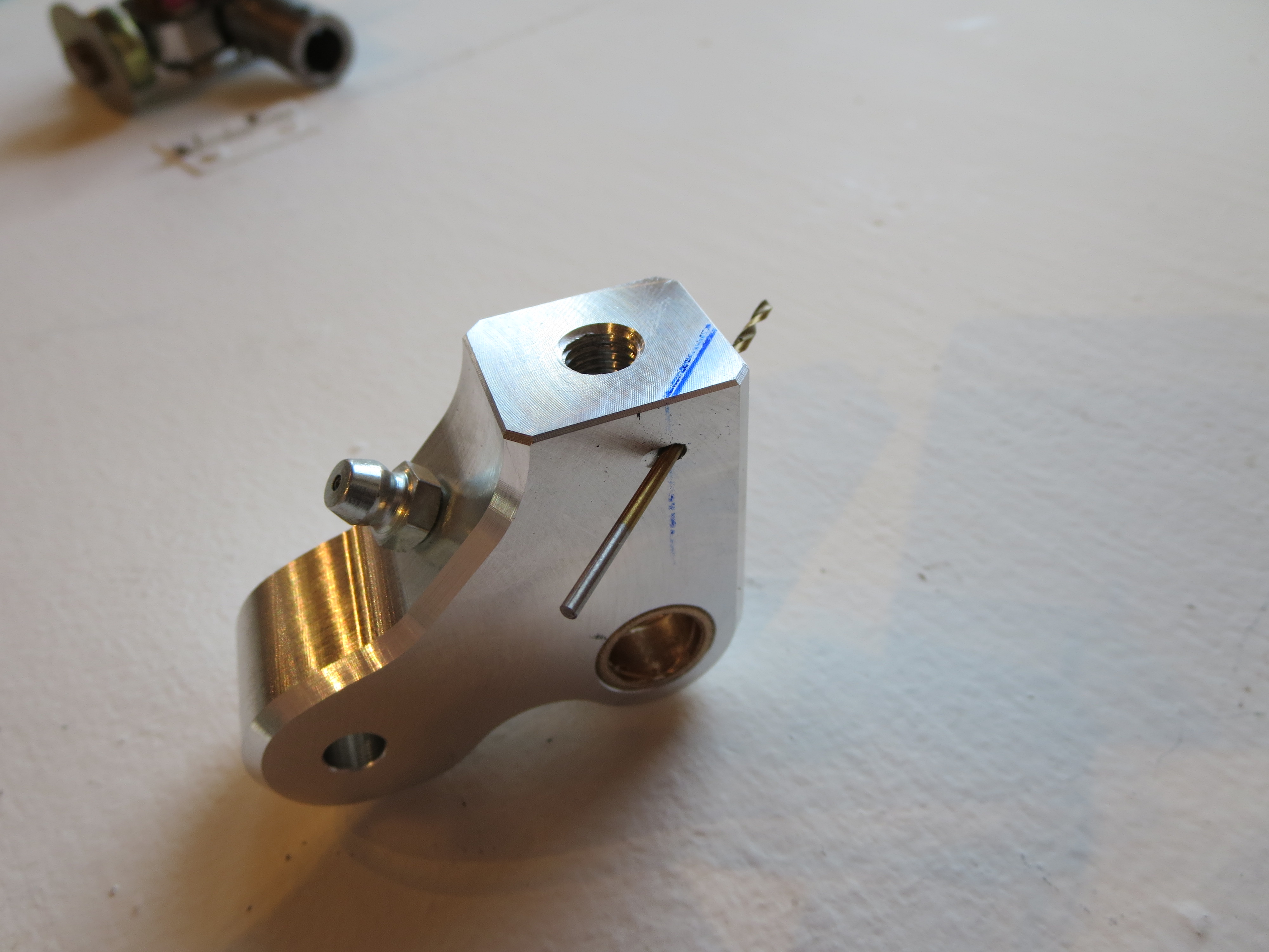
Start by drilling the hole for the safety wire on the fore/aft arm. On the collective slider I did them "free-hand". On this piece and with the mill and a couple of holding blocks this is achieved in very short order and with less hand wringing. Center punch the start location. Use a center drill to provide a "divot" so the real drill doesn't wander and away we go.
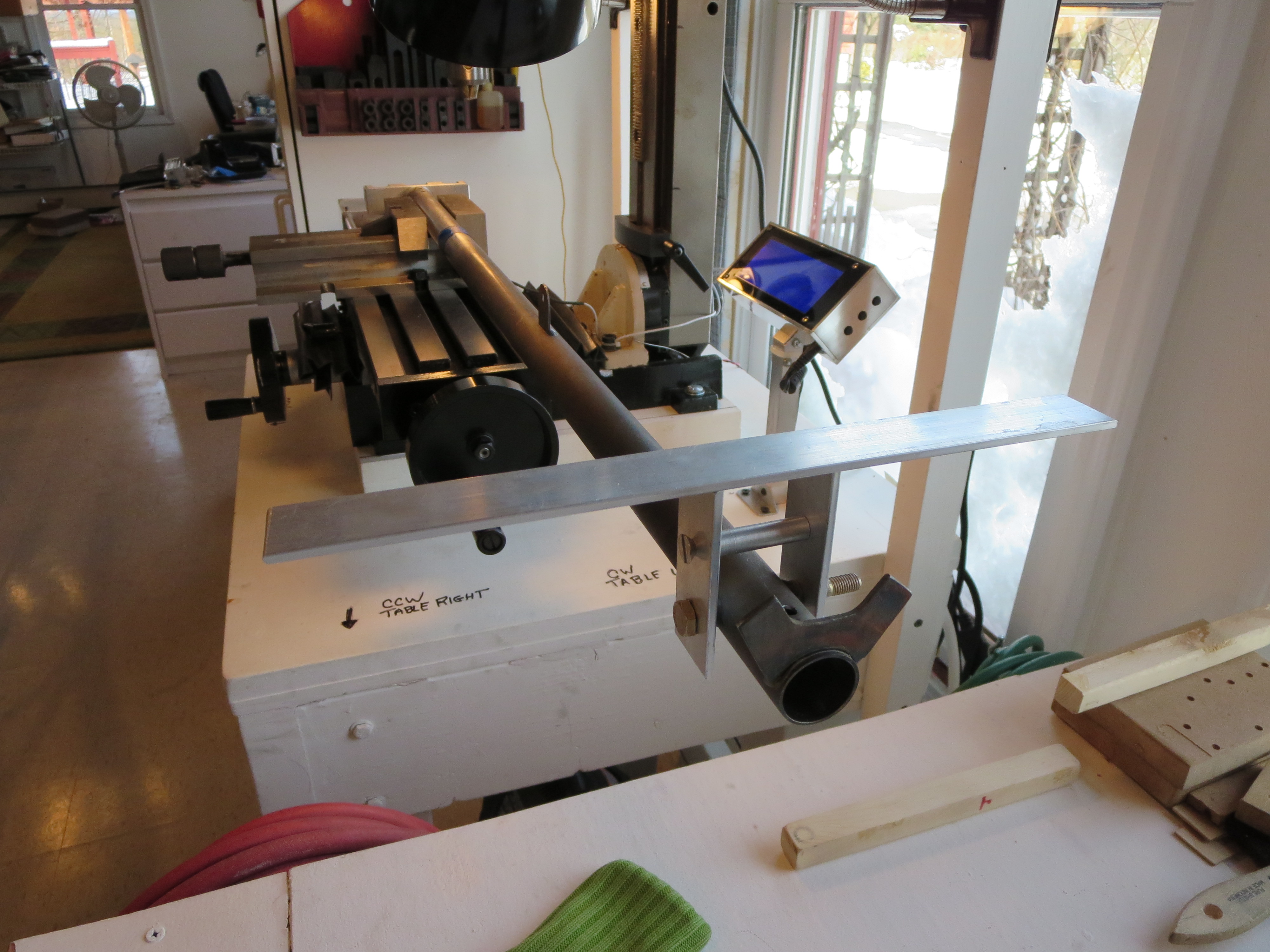
To precisely align the mixer with the control stick I made a little jig. Those two aluminum plates were machined in a stack, so they exactly match. The holes were drilled and the top edge machined to form a precise reference edge/plane. Both plates are exactly the same dimensionally. Then I made a little spacer on the lathe the exact same width as the cyclic bolt tube. Bolt 'em together and place a bar across the reference edges. My digital level was then used to get the angle between the reference and the bottom of the mixer block to exactly 0.0degrees.
Of course right when I was feeling smug and competent, BAM. The drill bit snapped off on the first hole. Crap! About half an inch into the hole. Of course you can't drill into a drill bit, so instead of boogering things up I stopped and stared at it for a while.
First I tried digging the broken bit out with a pick and needle nose pliers - no joy. Then I milled the hole slightly and the broken end of the drill bit. At least at that point I could remove the mixer block.
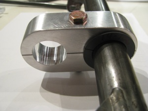
I tried using the "old" rearmost vertical hole first and matching the hole (you can see the hole on the left) Though very, very close, the hole on the other side of the tube was slightly oblong (by about 10 mils). I went ahead and drilled the horizontal cross bolt.
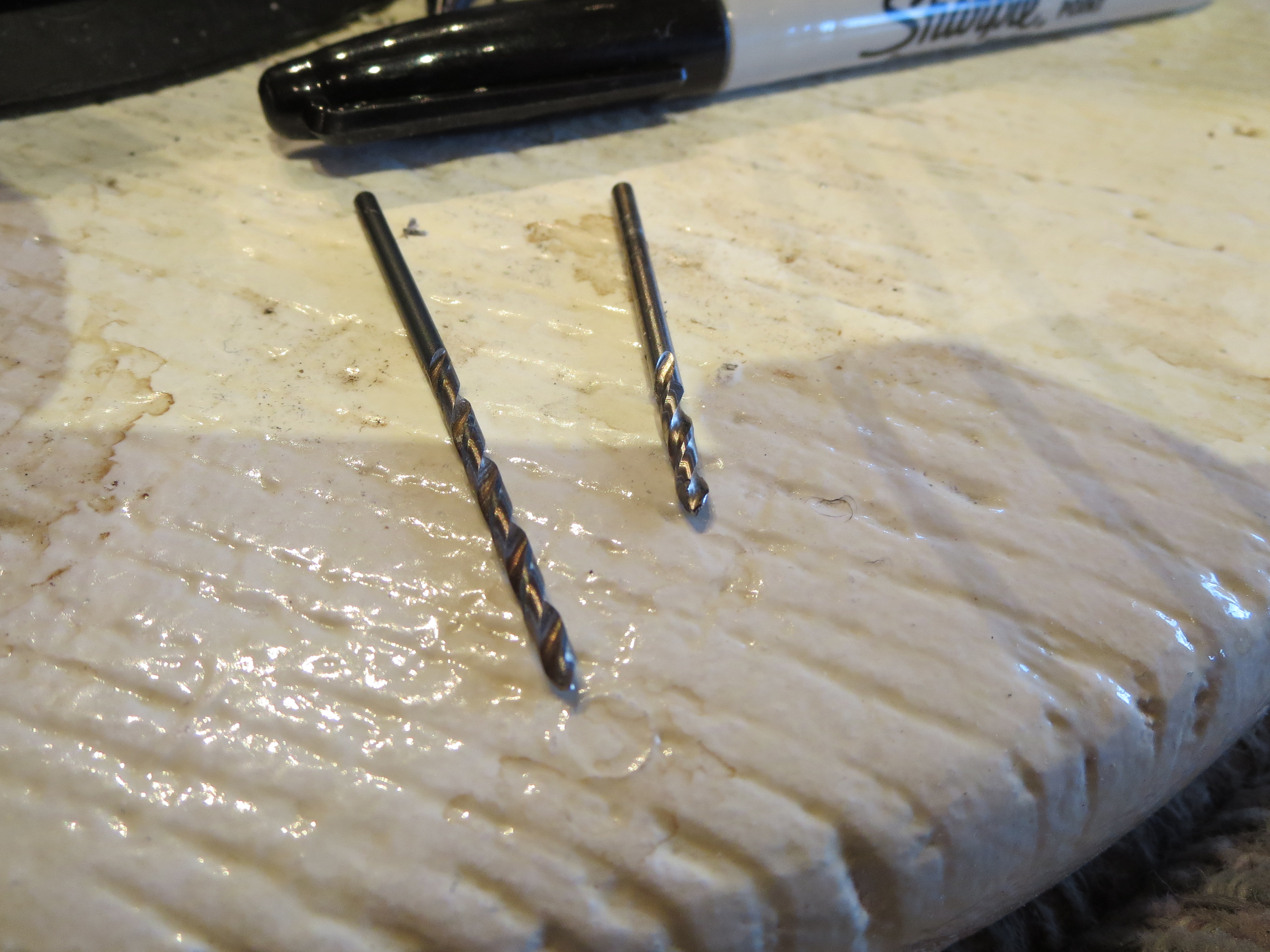
Why the bit snapped I don't know. It was only eating into aluminum at that point. It was well oiled, and I was backing it out regularly to clear chips. I was attempting to use a #30 bit as the pilot and that is probably a little wimpy for a hole this deep. Here you can see the remains of the broken bit with about 0.5" missing (in the mixer block).
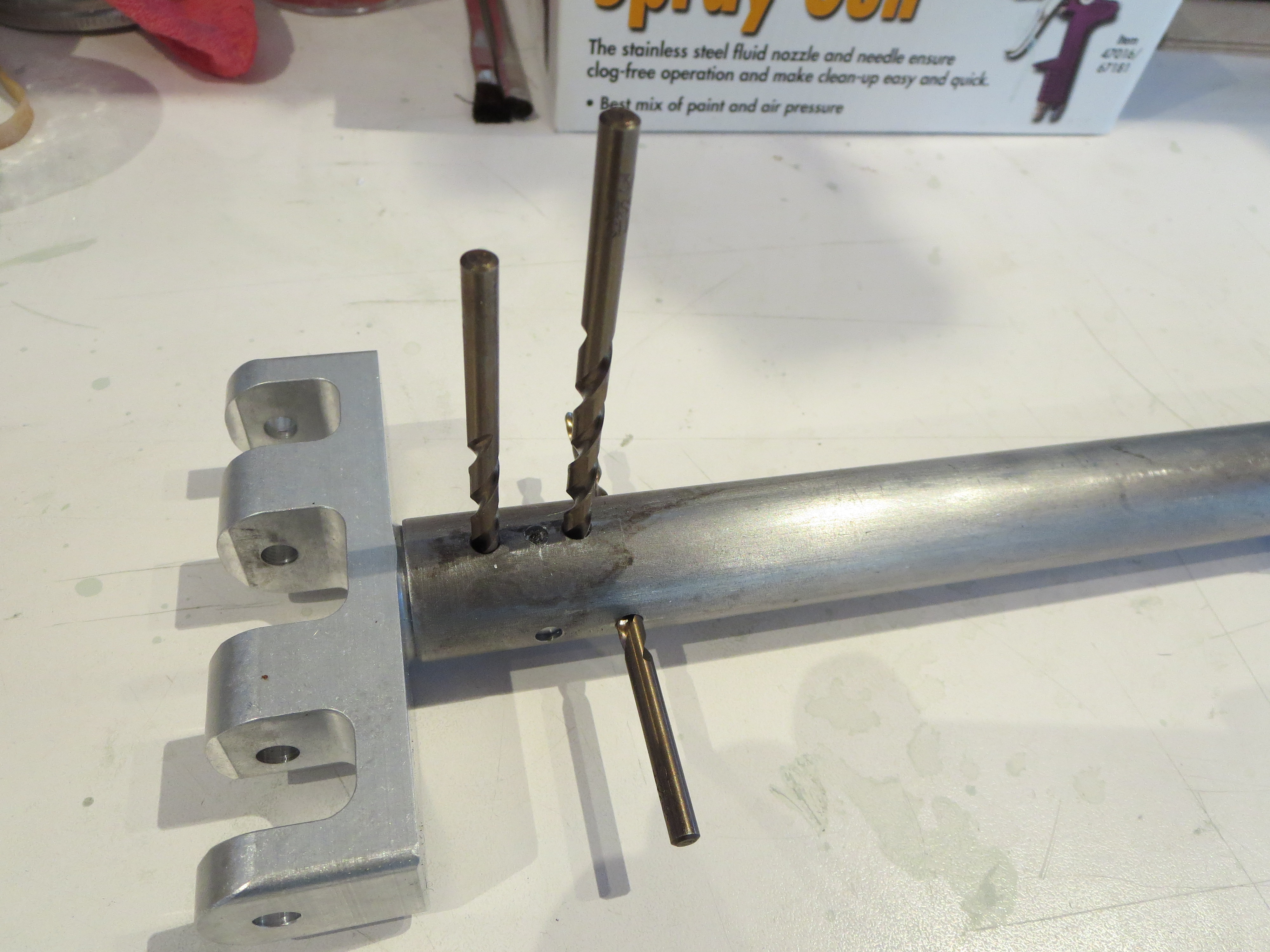
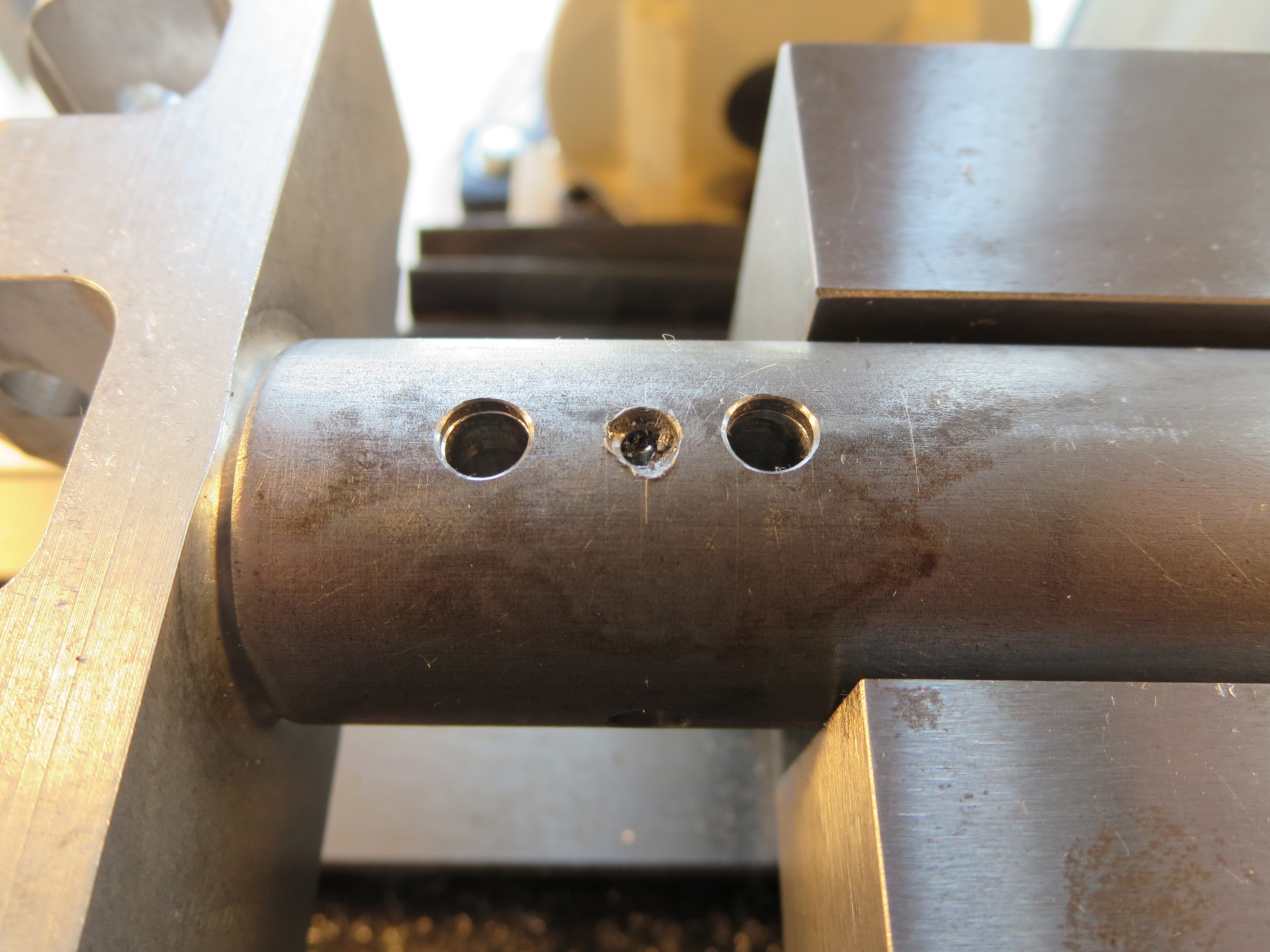
Even though it probably would have been OK, I carefully measured and determined that there was room for a third hole in between the others. You can see the middle drill bit here showing that hole. Pretty busy. The forward most cross hole is perfect, nice and snug. The rearmost one is the one I tried to match - sloppy on the far side. The middle is my auxiliary hole - also nice and snug. OK. Good. Crisis averted.
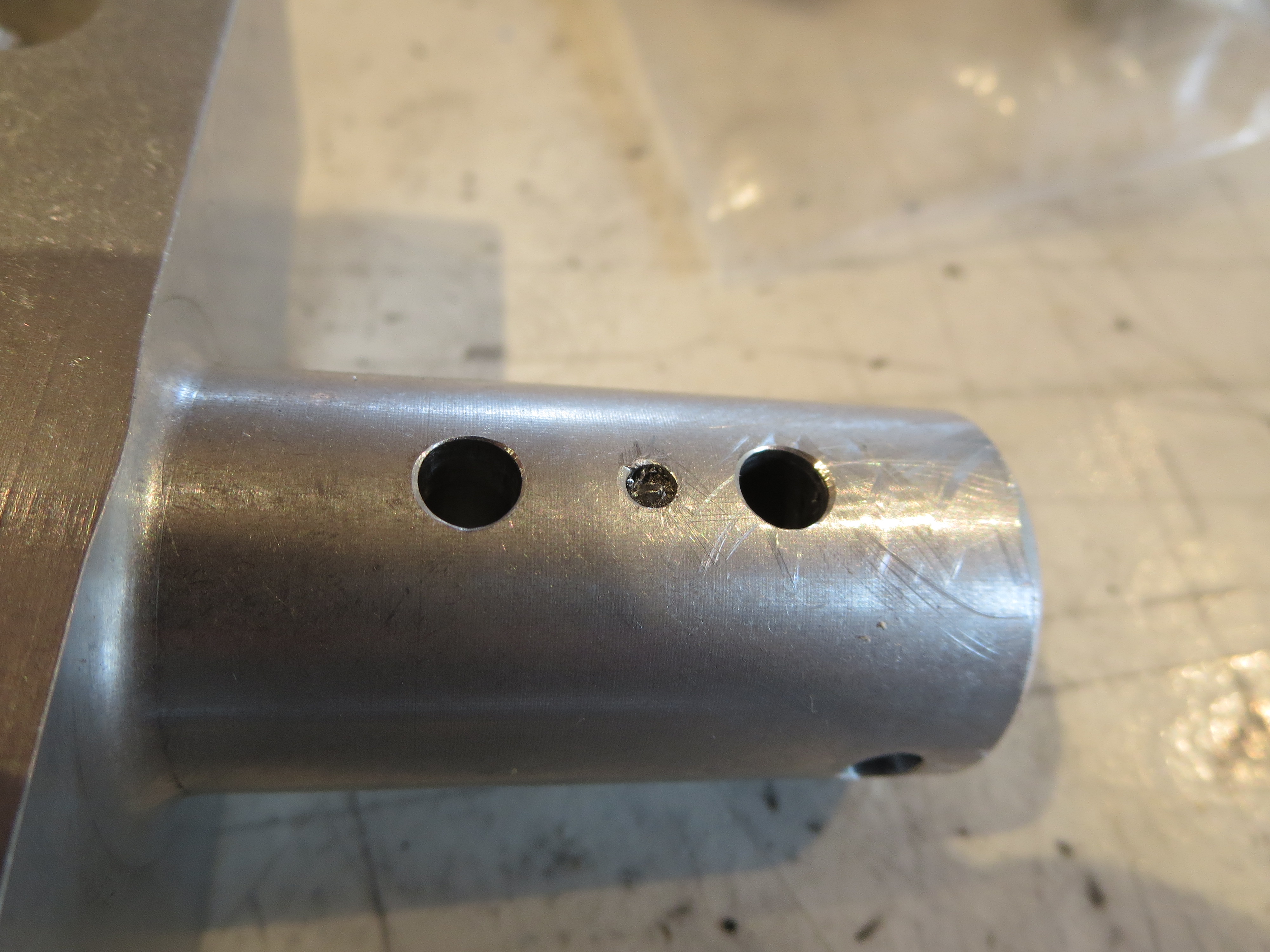
The mixer block removed from the cyclic control tube showing the three holes. Since it is solid aluminum I have no concerns over strength. The broken bit will ride along with me forever stuck in the aborted hole.
The rest of the mixer assembly is a non-event, just assembly with a little sanding to make everything slide together smoothly. Off to paint.
Collective Controls
03/13/11 18:02 Filed in: All
 Having wrapped up most of the fin construction I jumped into the collective controls. This is a pretty straight up section with light fitting and machining. It gave me a chance to use the mill/drill/lathe. That thing is cool. Way more precise than anything I could achieve with a drill press alone.
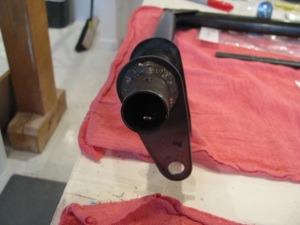
Start by drilling the end plug into the pivot end of the collective weldment. In the video BJ tells you to hammer a bolt into the aluminum plug. That didn’t quite sit right with me. So I lathed the bolt head down so it fit very snugly in the cap. The problem is that the “hammering” action is what would have held the bolt in the cap when the nut is tightened. Since the bolt is the pivot for the collective shaft it is not snugged down super tight. If it were to ever loosen up in there; a) There would be slop in the control, and b) it would be impossible to unscrew the nut off the end of the bolt.
So I measured and drilled right at the point of the bolt head, tapped the plug for little 8-32x3/16 set screws that will sit inside the plug, and drilled a little into the bolt head. Same treatment on both sides. I’ll install the bolt, and loctite the set screws. That bolt isn’t moving.
Of course doing this with just a drill press would be a pain, but the repeatability of the mill/drill allow the operation to be repeated easily from a fixed reference point.
The completed plug assembly.
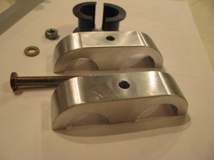
The collective is held in two places. The first is the pivot plug/bolt previously described, and the second is this aluminum construction. Two pieces of aluminum are supplied cut from bar stock. The corners must be radiused, which is no simple trick since they’re about an inch thick.
First the angle grinder, then the big belt sander and vixen file, then the little belt sander and sandpaper. This operation takes a lot longer than you ever would imagine.
The result is worth it, though. There is something very satisfying about shaping aluminum from rough into beautiful. If I elect to paint this the finish is ready to prime. If not, I’ll give it a bit of a polish and clear coat, but since it’s buried pretty deeply in the structure I’ll probably not invest the time.
I cannot find the supplied throttle grip in the parts bags, so I suspect it did not find it ‘s way to me when I purchased the kit. I ordered an aftermarket Harley Davidson throttle grip. The 1-1/8” OD throttle grip shaft matches the throttle handgrip on certain model Harleys (49 to 73, I believe). Plenty to choose from out there of all sizes and prices.
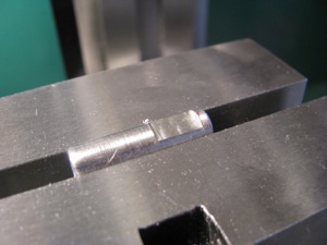
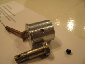
BJ tells you to 5-minute epoxy a length of 5/16 bolt into the end of the throttle twist shaft for the set bolt to “bite” into. Since I have to justify the expense of all this equipment, I milled a little flat onto the bolt section, just because it felt like the right thing to do. Instead of 5-minute, I JB Welded the slug into the end of the shaft after the hole had been drilled and positioned.
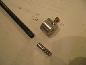
The slug, the shaft, and the collar that links the throttle twist shaft to the potentiometer shaft.
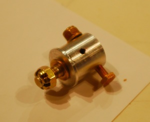
Potentiometer holder insert and bolted into place. This is actually a fairly complex machined part for such a simple function.
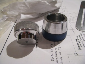
About 15 minutes of sanding and polishing were all it took to shine up the collective and throttle friction knobs. Mother’s Mag polish hasn’t failed me yet. Flitz seems to be recommended highly, but since I have two cans Mother’s, I am going to use it up first. I did mask off the knurled sections since the black polishing residue would probably be a pain to get out of there.
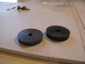
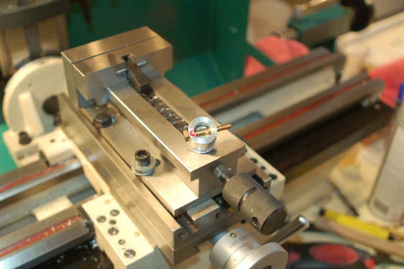
My parts bags only had a single plastic friction washer for the Collective Friction Assembly. The prints show one on either side of the collective friction slider bar, so I made one up from some plastic stock I had on hand. I think it’s phenolic. It feels similar in texture to the provided part. I am learning the lathe. Diameter is easy. Facing is easy. Parting and finishing the second side is not so easy on a part this thin. Parted with a hacksaw blade (it’s plastic), and was just able to get it in the chuck enough to face the second side. The tool was very close to the jaws of the chuck while facing.
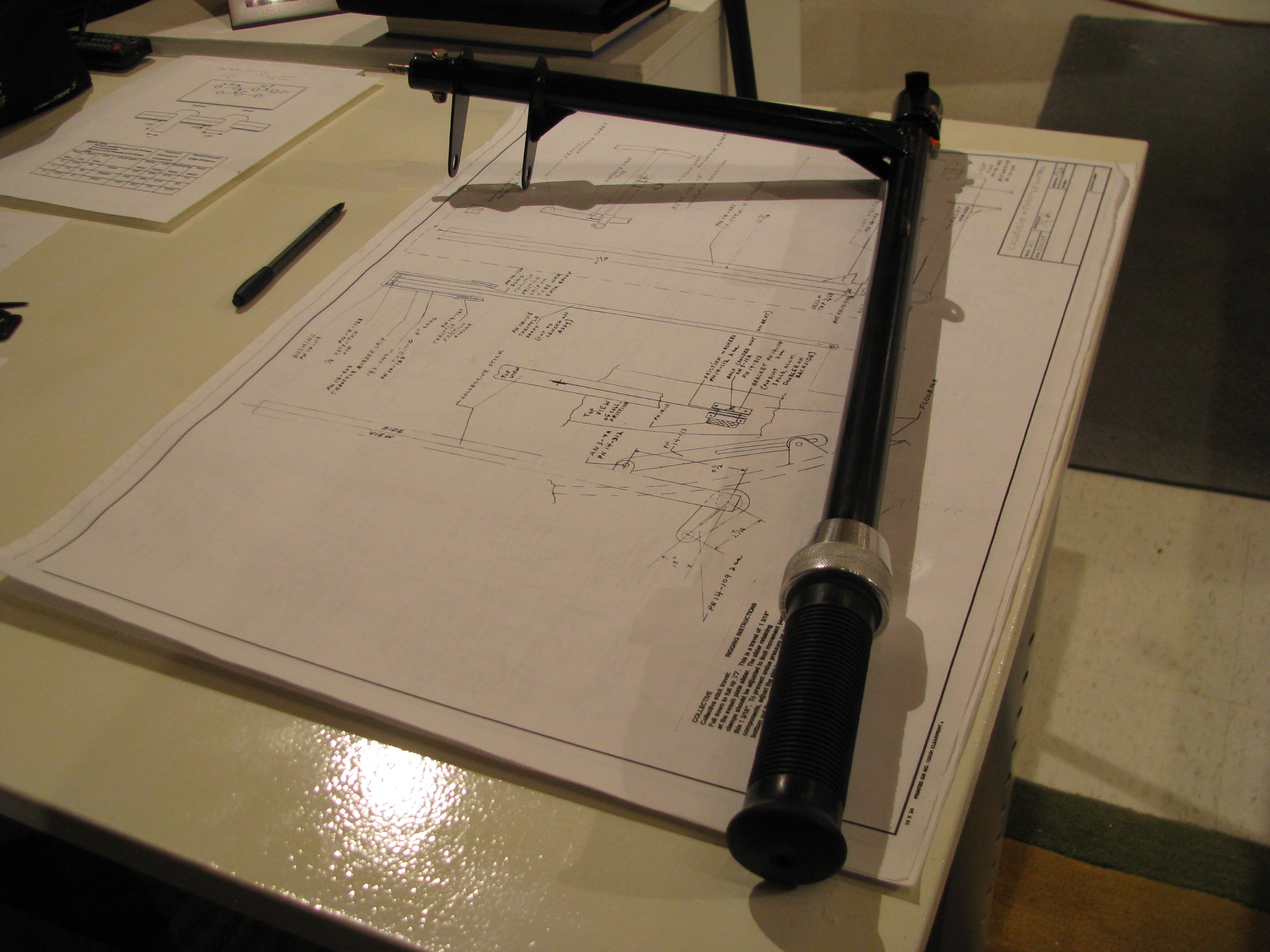
The completed throttle/collective assembly ready for installation into the ship. After experimenting with a few different grips, I ended up with one I bought just like the one BJ provides in the kit. It’s a Harley OEM-type throttle grip. None of the others I bought seemed appropriate for a Helicopter.
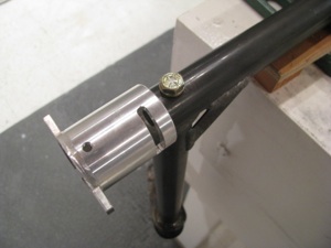
A light sandblast with 220 grit media to remove surface corrosion from the tube assembly and VHT single-part epoxy paint. Seems like good stuff as long as you let it cure for the many days specified before knocking it around.
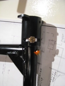
The potentiometer holder final bolted in place (obviously not the throttle pot linkage, though). Anywhere I “final” assemble a bolt and torque it to spec I use a little torque seal, not just as a movement indicator, but as a reminder to myself.
I can’t count the number of times I have let something sit for a week and then can’t remember if I completed this little operation or that. Any/all reminders help my advancing memory.