
Bodybuilding
N-Number Reserved
01/07/14 23:45 Filed in: All
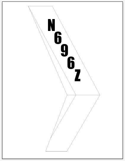
Hooray! I got notice of my reserved N-Numbers from the FAA today. Though not difficult to get or an especially tricky milestone, it IS an indication of the project progressing.
I ordered some custom vinyl lettering from DIYLettering.com; Pre-cut green vinyl letters 3.5" tall. The font is "Impact", which looks very readable.
Pedal Slots
03/31/12 22:54 Filed in: All
After not touching the body for a long time I am reassembling things so that I can fit the instrument pod.
Here I have cut the slots for the rudder pedals. Not trusting the scribe lines, I sort-of slid the pan on with the pedals in places so I could mark the locations for the cuts. Just using the scribed lines on the pan would have meant slots about half again wider than they really need to be since they were quite a bit offset from the actual pedal locations.
Chin Window Drilling & Cabin Fiberglass
10/11/11 22:50 Filed in: All
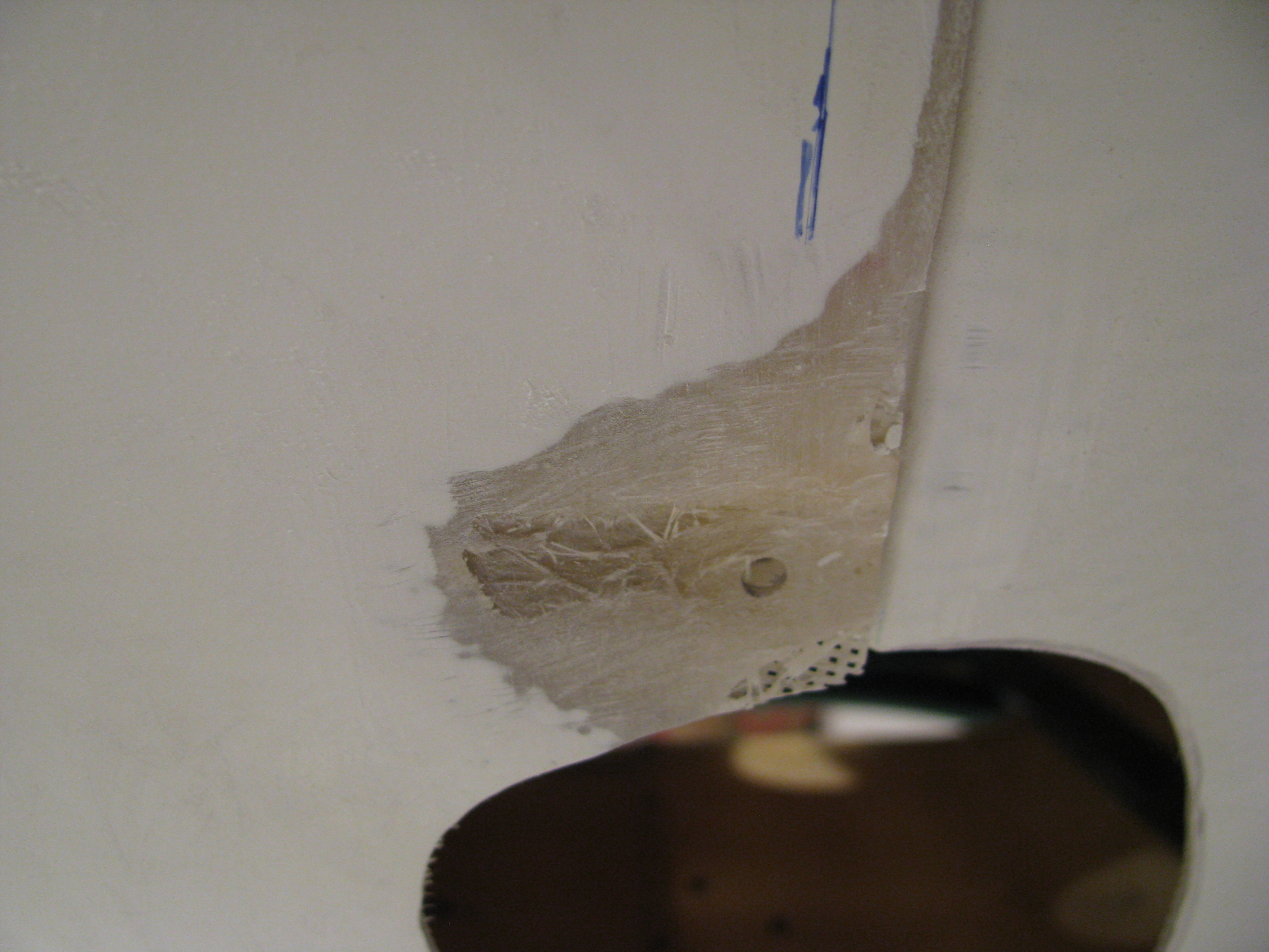
Cleaning up a lot of little things. Here is a spot on the body that was bubbled and mostly gelcoat. Ground it out, heat and flattened the fiberglass with a heatgun and pressed it between some angle to straighten . Finally layed up a couple of thin layers to add strength and bondoed to smooth it out.
There were a couple of spots that required this treatment.
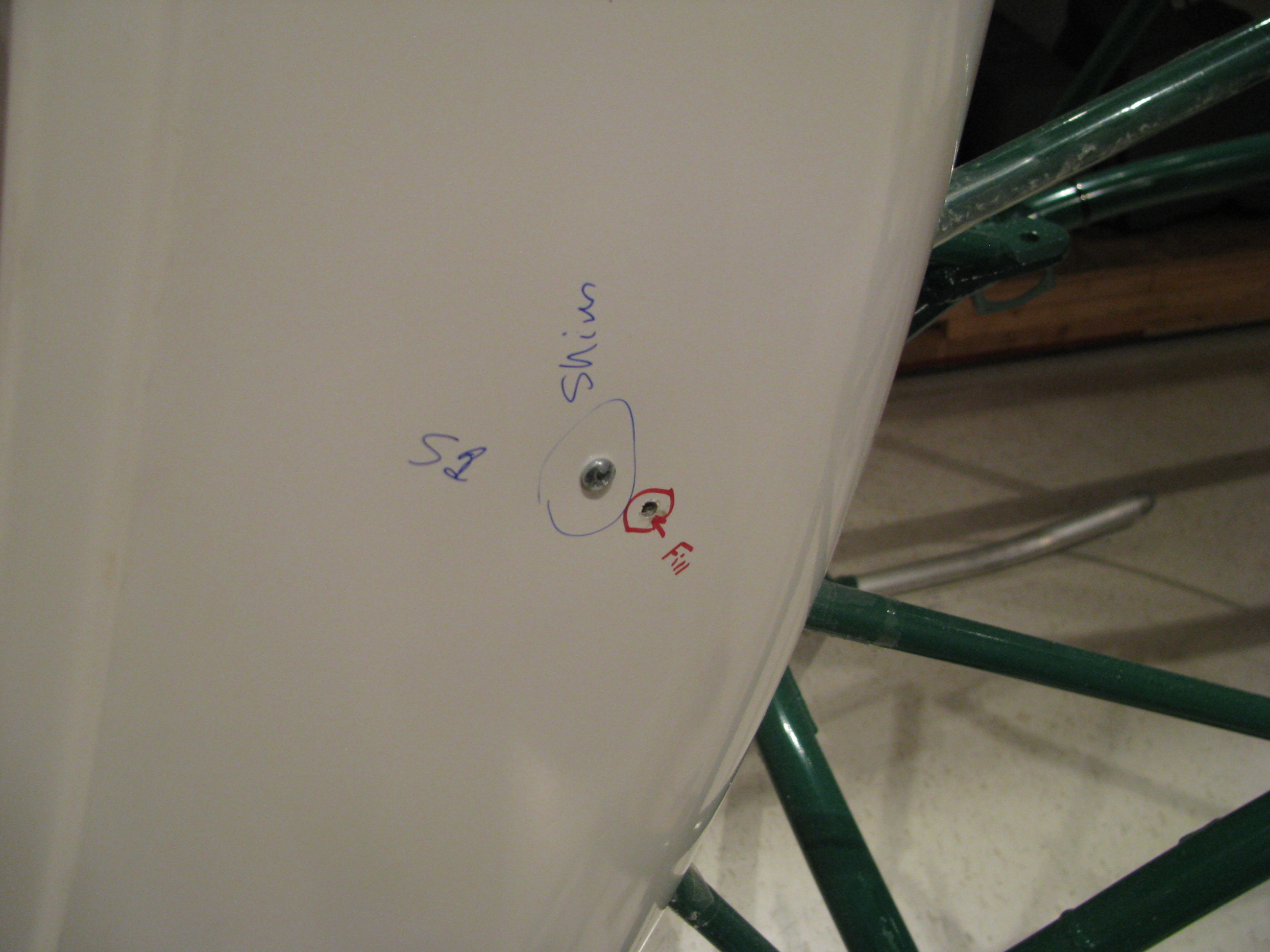
Here is where the pre-drilled holes didn’t quite line up with where the floorpan actually fell. Had to drill a new one and fill the old.
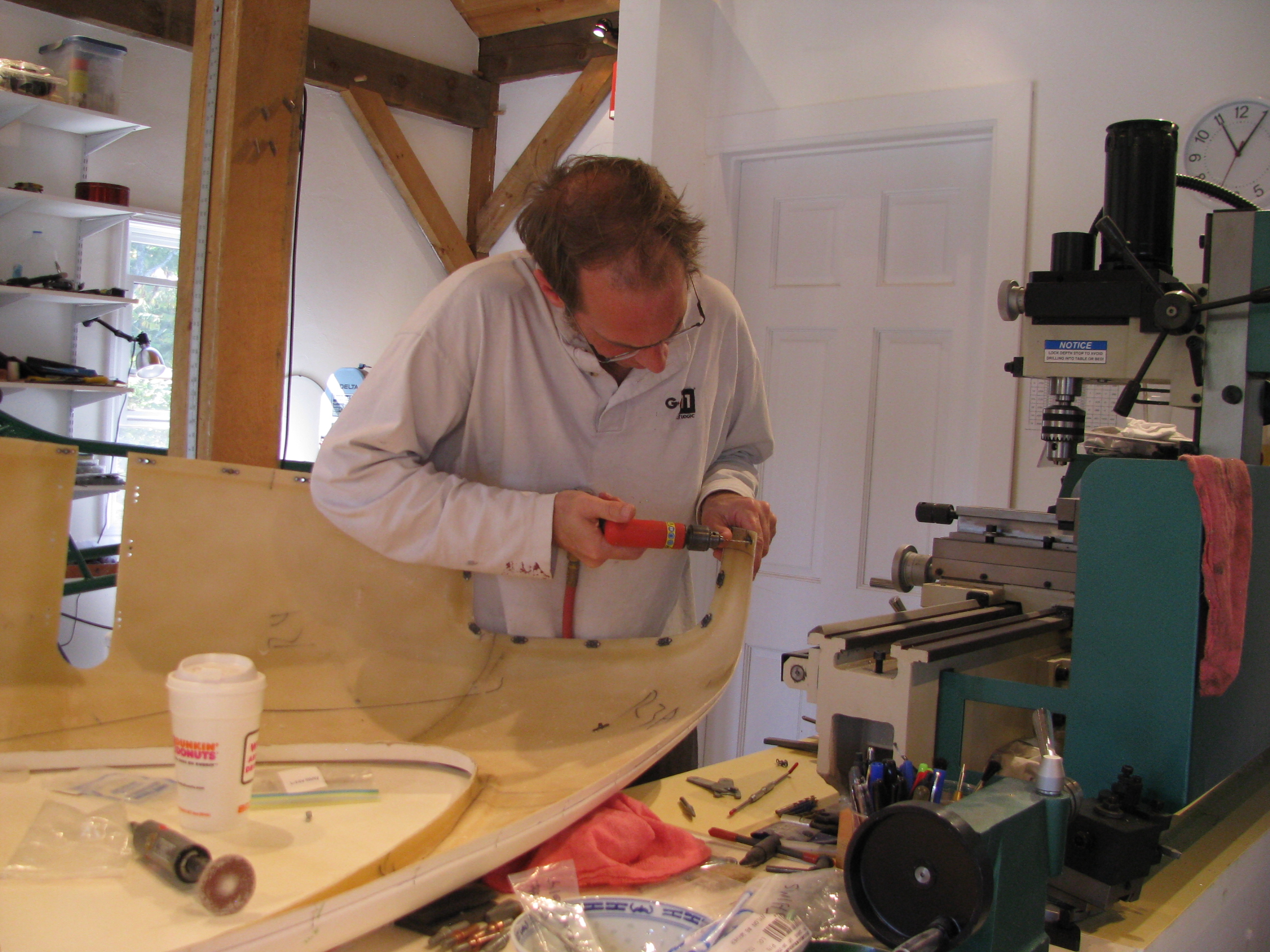
FAA required picture of me working. Gotta remember to get more of these. Since I am usually working alone it means getting out the tripod and setting up the camera timer. Coffee fueled build process.
Holes are easy to drill, but each one needs a nutplate and there sure are a lot of them. Here I am drilling and mounting the chin window floating nutplates.
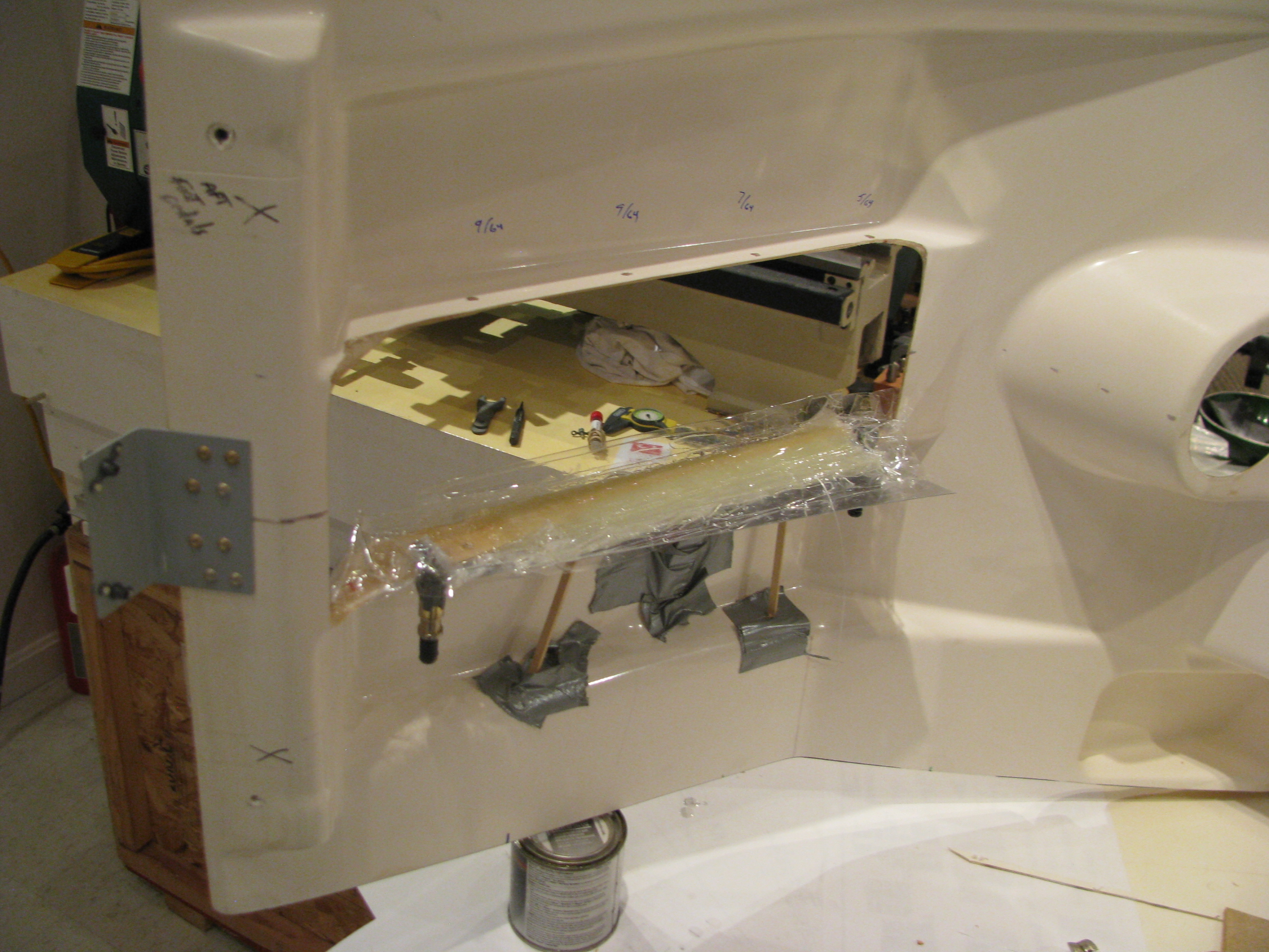
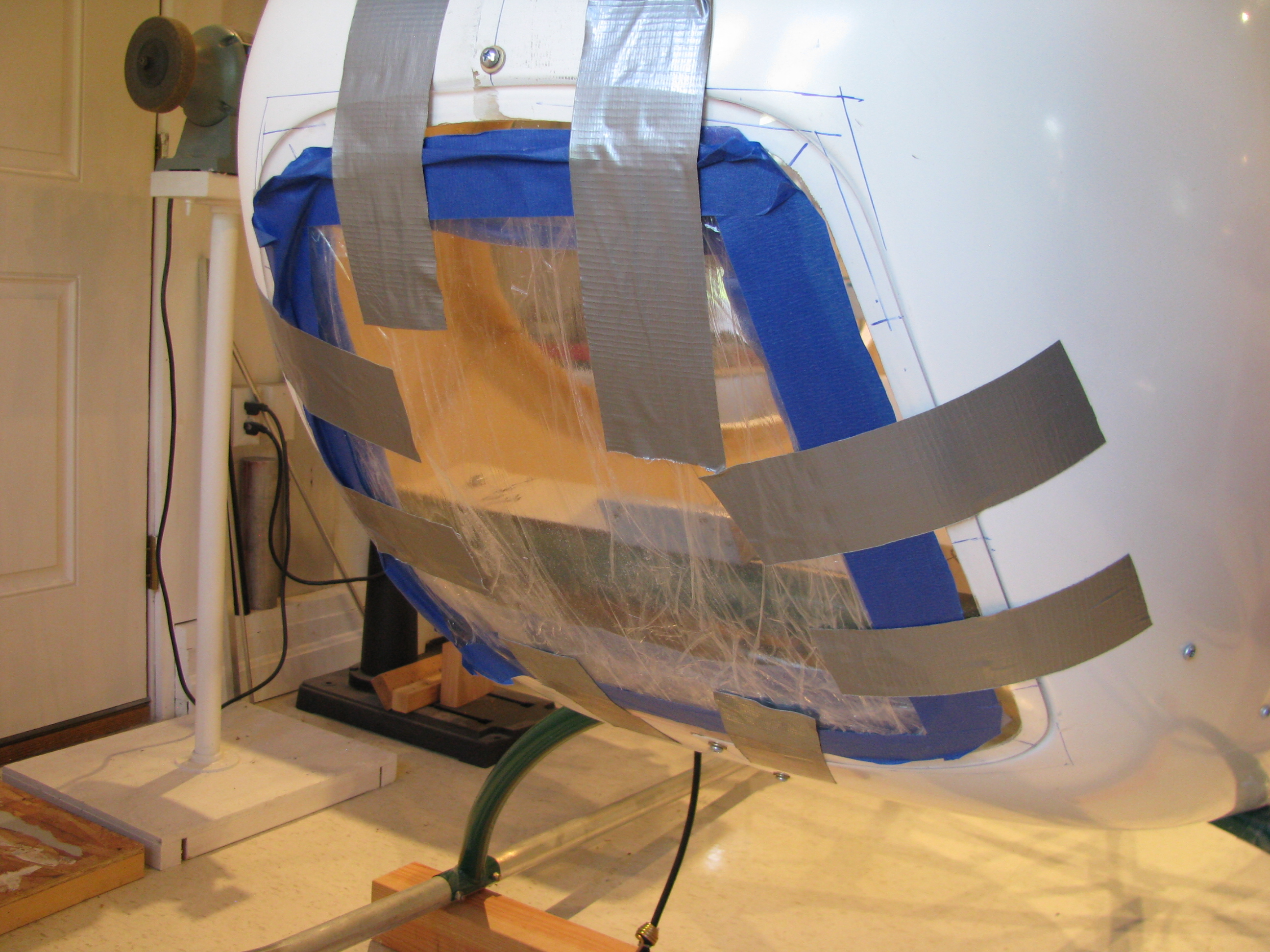
There’s a lot more fiberglass work than I anticipated. This is the lip of the floorpan along the base of the instrument pod. The drilled holes cut through the edge of the lip.
I had to first cut away the fiberglass with the partial holes. A dam was built with packing tape and a tape covered aluminum sheet. Then an thin layer of flox to allow the edge to form, then five layers of cloth. I’ll have to sand a lot of it down, but it should allow for a tight fit with plenty of meat around the holes. It’ll be a lot “taller” than the original lip.
In a few places I had to shim the pan, especially up around the curve of the top of the body. A layer of foam sanded to the correct thickness, then glassed over. To mount the nutplates behind the lip I had to cut a strip of aluminum, mount the nutplate, then rivet it outside the foamed area.
Drilling Windscreen & Bodywork
08/11/11 22:46 Filed in: All
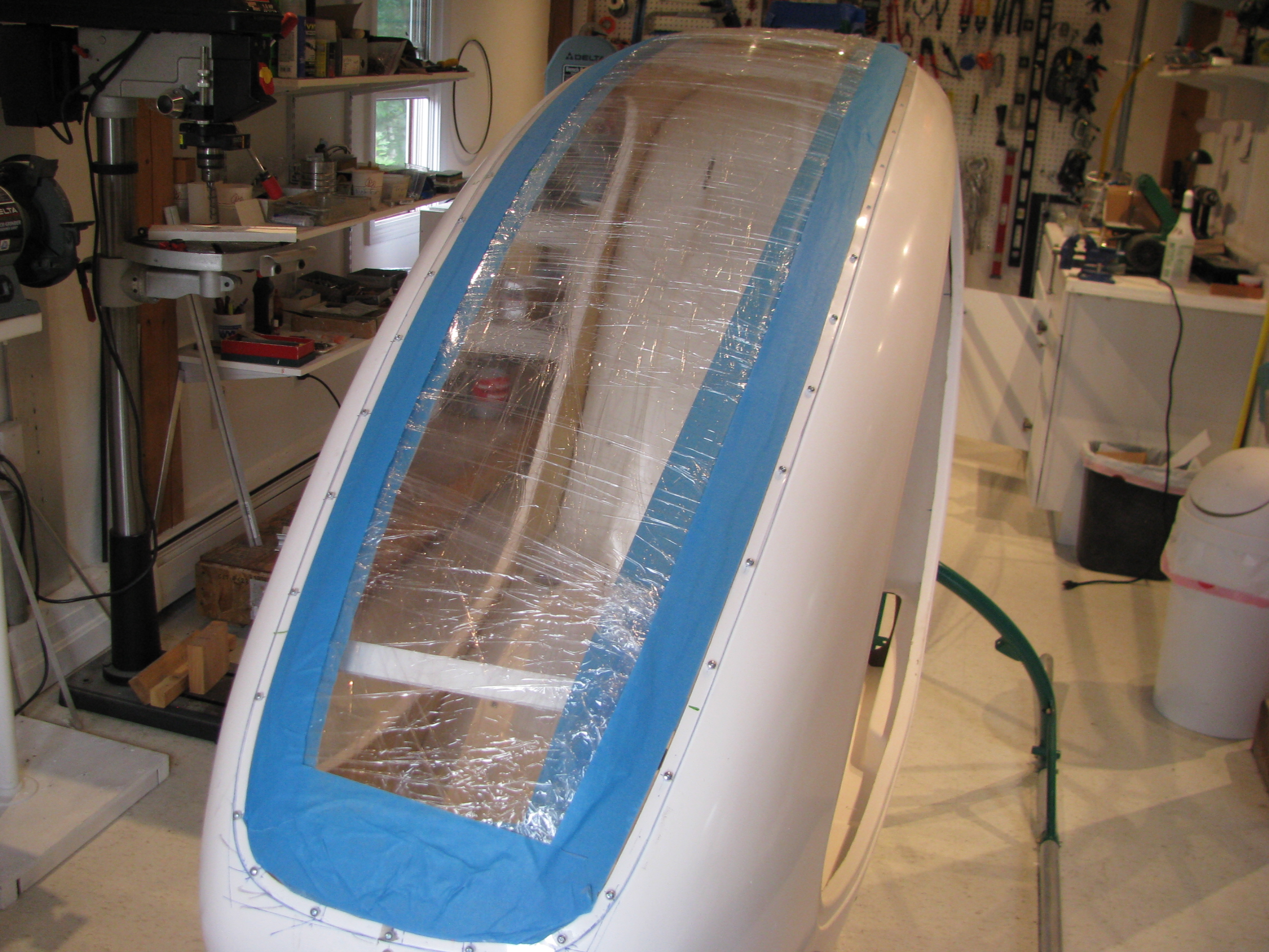
It’s been a few weeks with slow progress. I fitted and trimmed the windscreen and lower plexi and drilled them to the frame.
The windscreen and lower window really add a lot of strength to the cabin. It’s pretty solid now. My shop was about 90 degrees, so the plexi was pretty flexible and the holes drilled cleanly. Only a few will need some sanding and beveling as there looks to be a chip or two on the backside.
Most of the holes look like this after drilling and beveling. Overall I am pleased with the result
Initial Screen Fitting
07/22/11 22:39 Filed in: All
Lower plexi taped in place on front. Lot’s of trimming to fit the joggle cleanly. It has been drilled and I purchased a bunch of #6 floating nutplates after having read the experiences of others. Apparently with the instrument cluster in place there is almost no way to get your hands in there to place acorn nuts.
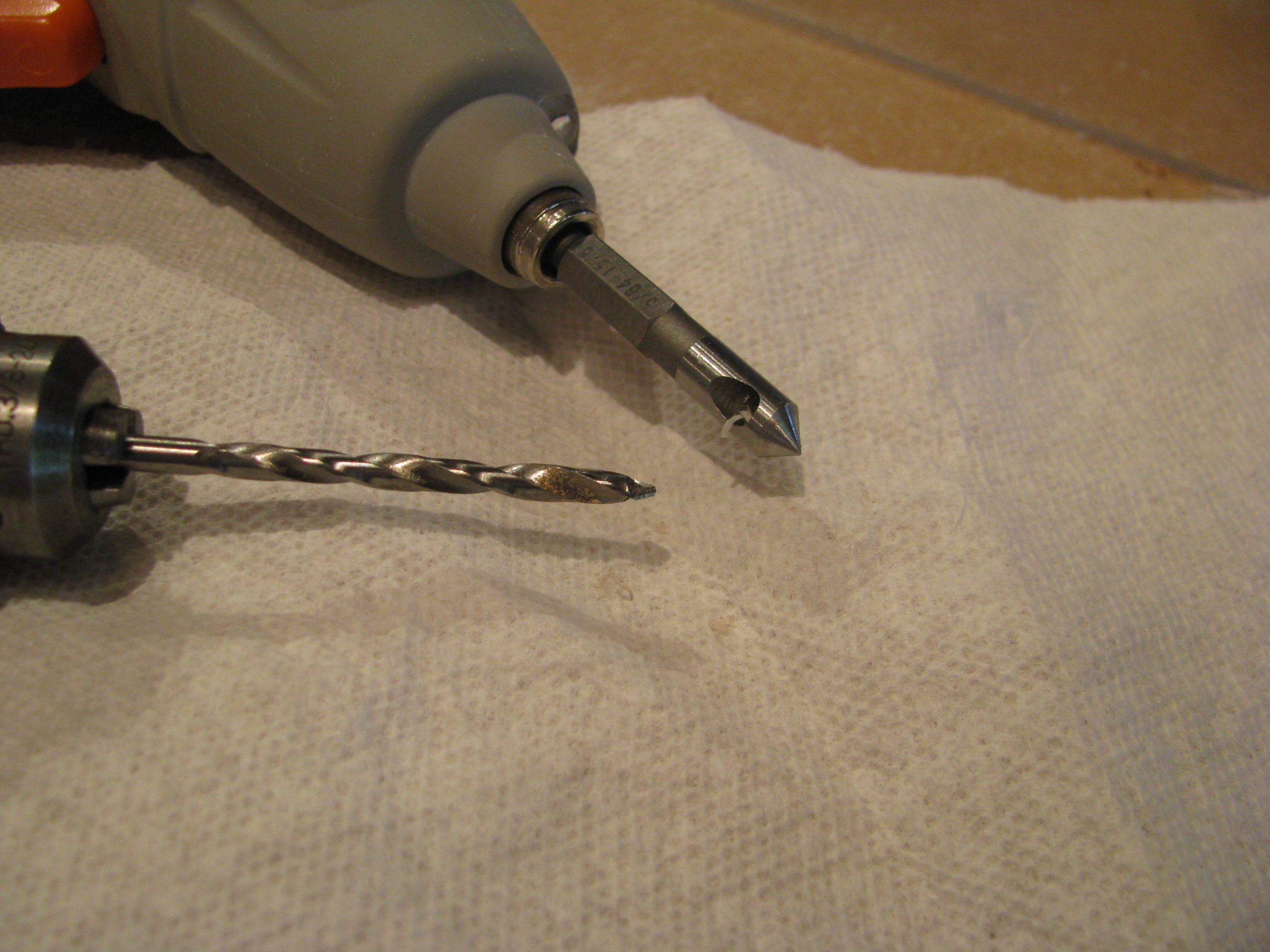
Here is my dynamic duo for drilling the plexi. The drill bit is a #27 plexi bit from Avery Tool. It has a shallow cutting 60 degree point. The countersink I picked up from the sale bin at Harbor Freight. It has a single flute and just barely shaves, which leaves a nice, chatter-free chamfer on the plexi holes. $3.99 for a set of three. It would probably dull immediately on aluminum or steel, but it’s great for this application.
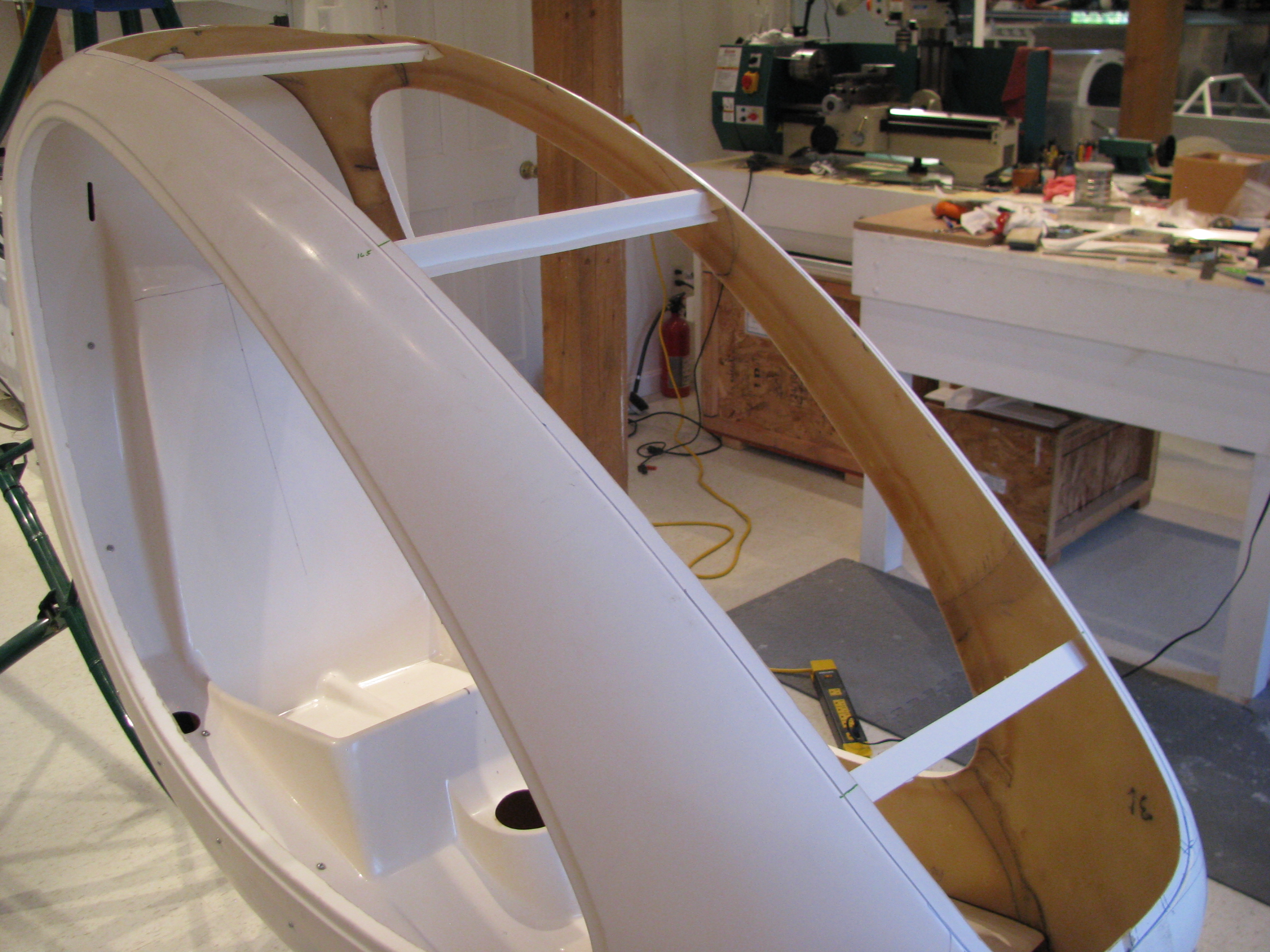
The windscreen opening is pretty floppy without the windscreen. I hot glued some foamcore “I-beams” to hold the width to almost exactly match the windscreen. Makes fitting and holding the windscreen in place much easier. I thought peeling the hotglue out would be easy when I’m done, but I tried peeling off a blob and it really, really grips that rough fiberglass pretty securely in fact. Oh well.
Drilling Cabing Halves
07/18/11 22:26 Filed in: All
Spotty progress due to work travel. Two trips to Mexico and one to California. Enough excuses - I tweaked the seatpan mounts as much as I could to get the body to fit better. The two rearmost pre-drilled holes on the left side won’t work no matter what I do, though, so they have been repositioned about an inch forward. The existing holes will be filled.
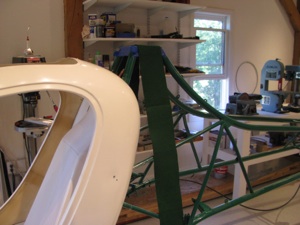
Body halves drilled all around. Straps, cleco clamps, and an extra pair of hands helps here a lot There are really no straight lines or easy reference points to tell whether it’s square and symmetric. Lots of fitting, standing back and eyeballing, then tweaking to make it as square as possible. About 14 or 15 screws from the front to the seatpan top curve. I’ll shim and drill the very top of the seatpan curve once the windscreen is in place.
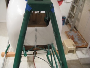
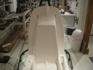
Rear of the body. The cutouts don’t match exactly, but that’s OK. I’ll trim them in place.
I found some green felt that is a very good match to the frame powder coat color. I will use some spray adhesive and use that on the body shell interior when I get to that point.
Body halves drilled all around. Straps, cleco clamps, and an extra pair of hands helps here a lot There are really no straight lines or easy reference points to tell whether it’s square and symmetric. Lots of fitting, standing back and eyeballing, then tweaking to make it as square as possible. About 14 or 15 screws from the front to the seatpan top curve. I’ll shim and drill the very top of the seatpan curve once the windscreen is in place.

Rear of the body. The cutouts don’t match exactly, but that’s OK. I’ll trim them in place.
I found some green felt that is a very good match to the frame powder coat color. I will use some spray adhesive and use that on the body shell interior when I get to that point.
First Cabin Fit
06/21/11 22:21 Filed in: All
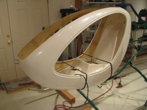
First fitting of the body halves. Of course they had to come off and on about a half dozen times to fine tune the cutouts around the body tubes. The powder coat on the body tubes got fairly scratched up in a few places before I had them all taped up to protect them, I’ll have to get some touch up paint of the same color.
The fit is pretty poor. I think my seatpan sits forward perhaps too much which makes the vertical holes on the sides impossible to line up on the left side without really deforming the seatpan. I may have to pull it all apart and redo the seat pan mounts so everything fits more cleanly. Darn. I thought this was going to be an easy bit.
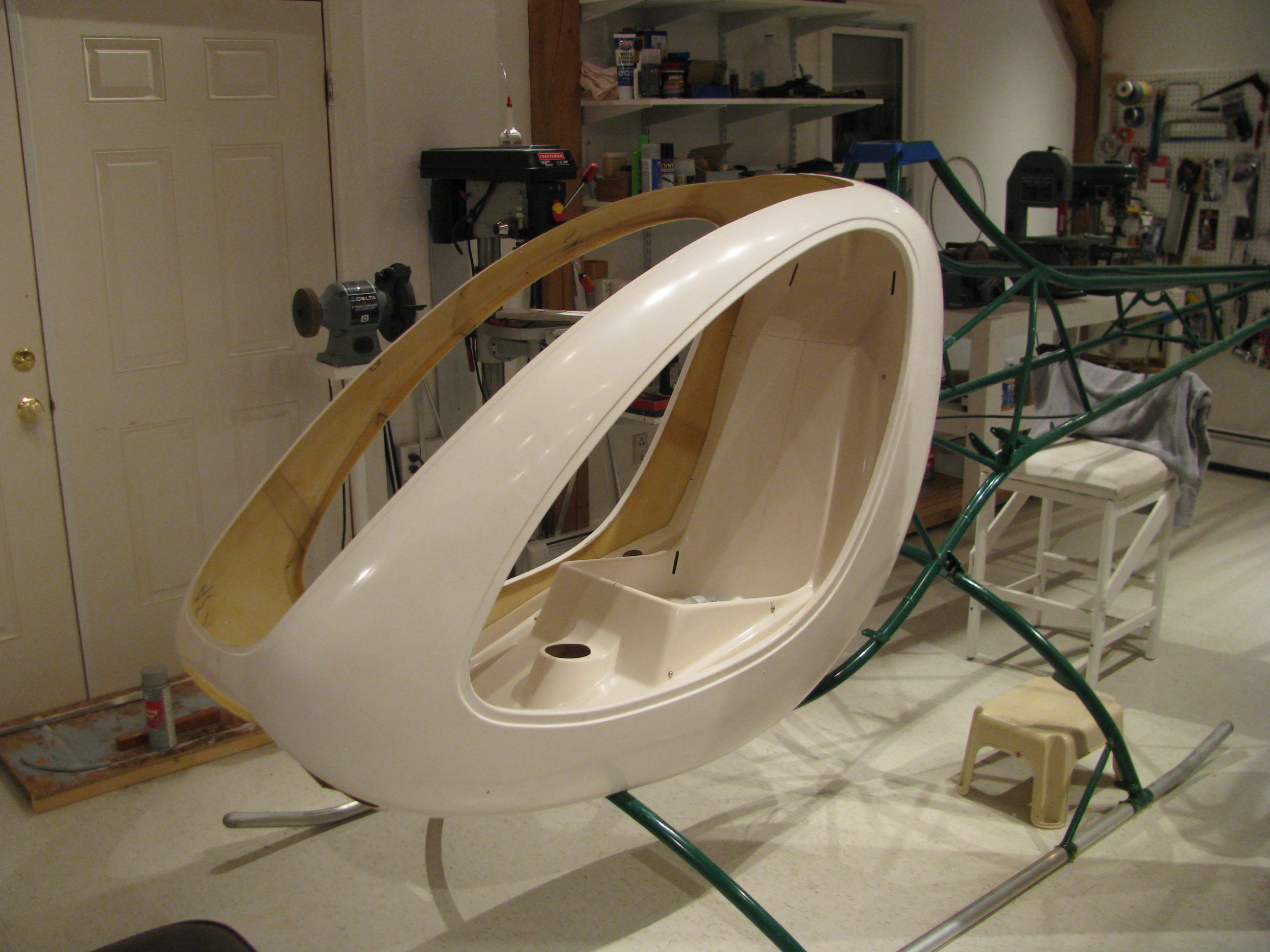
Anyway, it really looks like a flying machine with the body attached and I had to strongly resist the urge to climb in, make airplane noises, and daydream. The frame came powder coated dark green. I had been thinking dark yellow for the body, but perhaps a very stark white would work with polished skids and blades and grey Zolotone on the interior. Too soon??
Pan Drilling
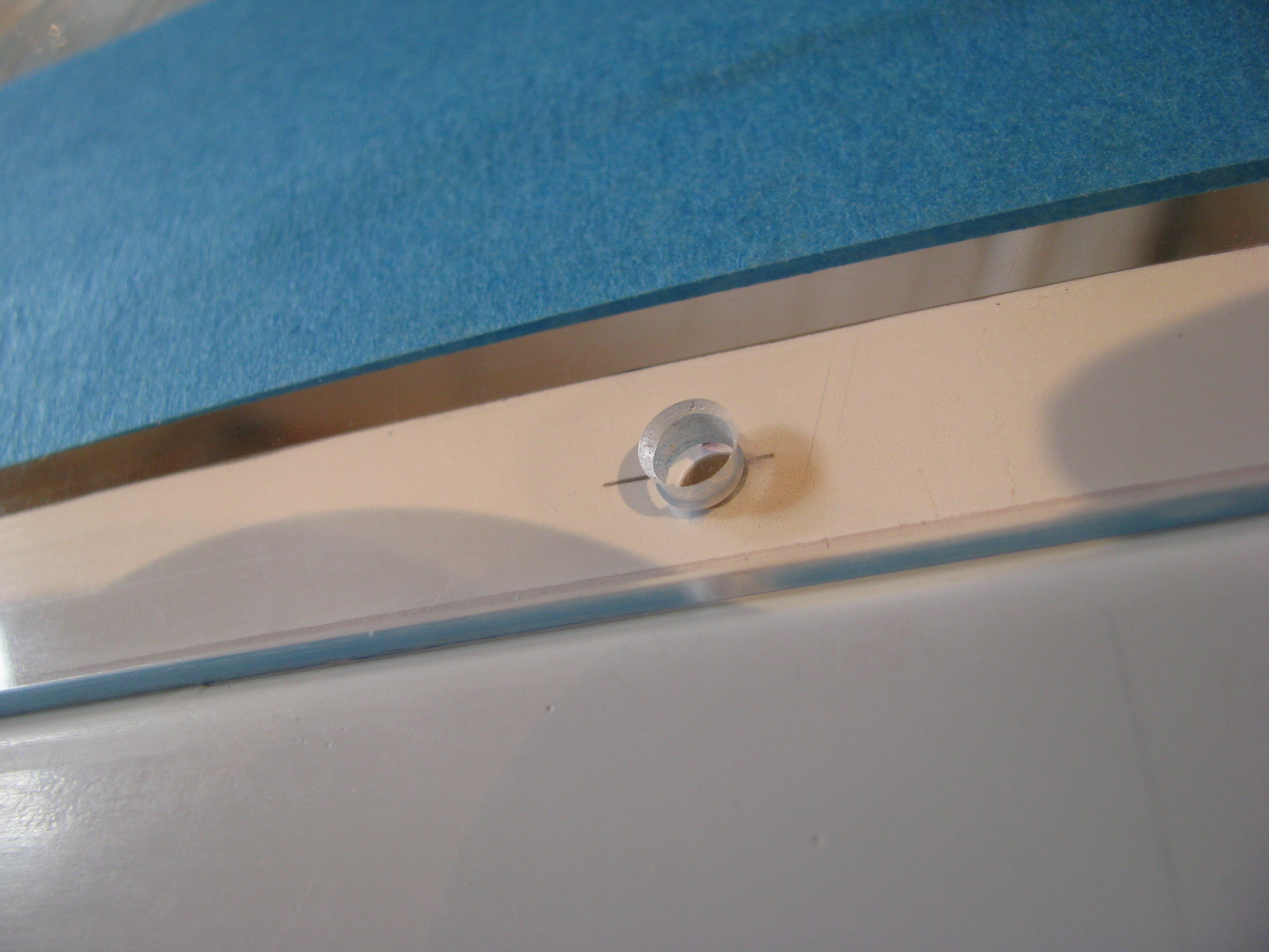
06/15/11 22:06 Filed in: All
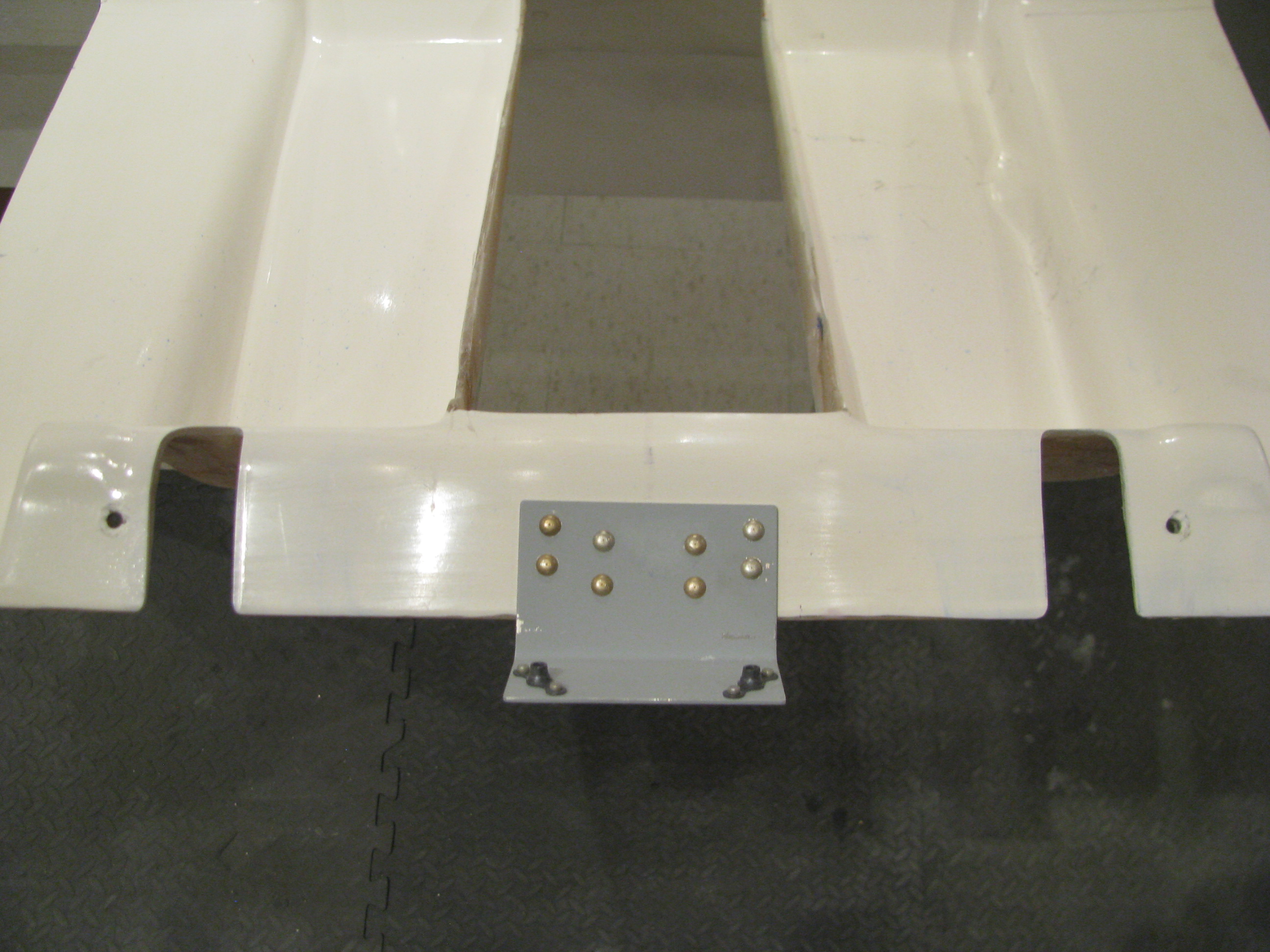
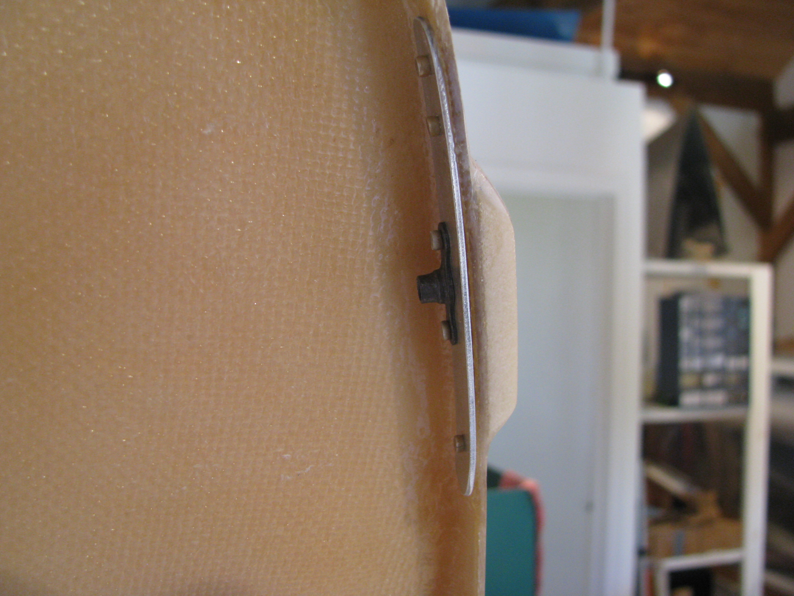
Finally got around to drilling the pan to the frame. It took a little more flox and some sanding to get things perfectly level and the tabs in place without much bending of the tabs (only a couple needed very minor tweaking).
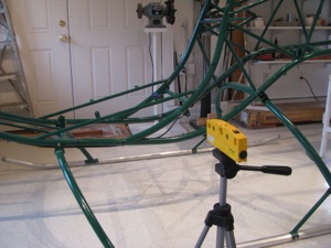
To drill the “blind” hole I first marked the arc at the correct distance, and also lined up a laser level with the hole from the outside. I started with a tiny bit and worked up to final, tweaking the position while checking from the inside.
It was only maybe 10 mils off by the time I got to final size. Not bad.
More BodyWork
05/23/11 22:01 Filed in: All
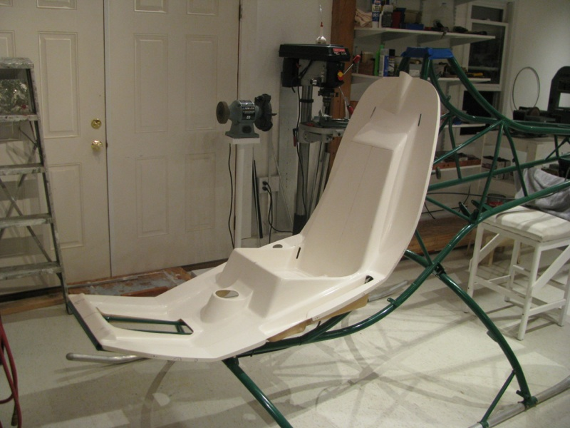
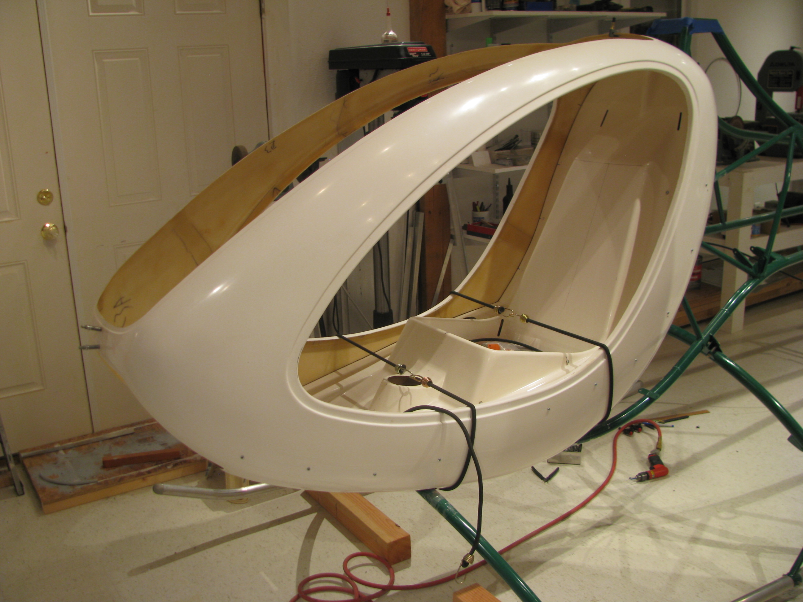
With the controls initially fit, it’s time to get back to mounting the seatpan and body shell. When I last left this task I had done all the fitting of the pan, and added some flox pads to fill the gaps between the pan and the metal tabs. They’re fit up pretty well and tomorrow I’ll drill the floorpan bolts.
The pan pretty-well centered. The hump at the top is slightly offset to the right in this picture. This is because the mast will be slightly offset as well and the control rod presumably goes to the center of the mast.