
CNC Mill
I did not want to spend a lifetime converting the machine, nor did I want to spend more than about $3500. This machine is substantial enough to cut up to maybe 1/2" aluminum. Parts and plans are readily available. I procured all the bits and pieces, and budgeted 3 weekends for the conversion. It took about three times that long as there is a lot of fiddling to get things dialed in perfectly.
The conversion deserves its own page, which can be found here: CNC_MILL.
Shop Day
The camera has the ability to monitor for motion, and then push images to an FTP server every second when there is motion detected. I then use an application called "Time Lapse Assembler" to string them into a movie.
Here is a day in the shop. The only frames logged are when I am in view and there is enough motion to trigger the camera, so it is not a full day, but several hours worth. Still, it's pretty big if you chose to download it.
This will get more interesting when there is more action on the airframe. Most of this is engine prep work. With a low-resolution video camera like this it makes for a pretty boring video. I will remedy that soon enough.
Tasks accomplished on camera:
- Safety wiring some engine fittings
- Doing the last bit of engine wiring.
- Torque sealing a bunch of bolts (my way of indicating completion)
- Fabricating, painting and installing a bracket for the throttle return spring
- Checking the clutch travel and figuring out how it mounts in the ship again.
- Replacing the skid bolts with AN HW of the proper length (the kit-supplied Grade 8 bolts ones are too short).
- Prepping the rubber clutch mount
Engine Hoist Bracket
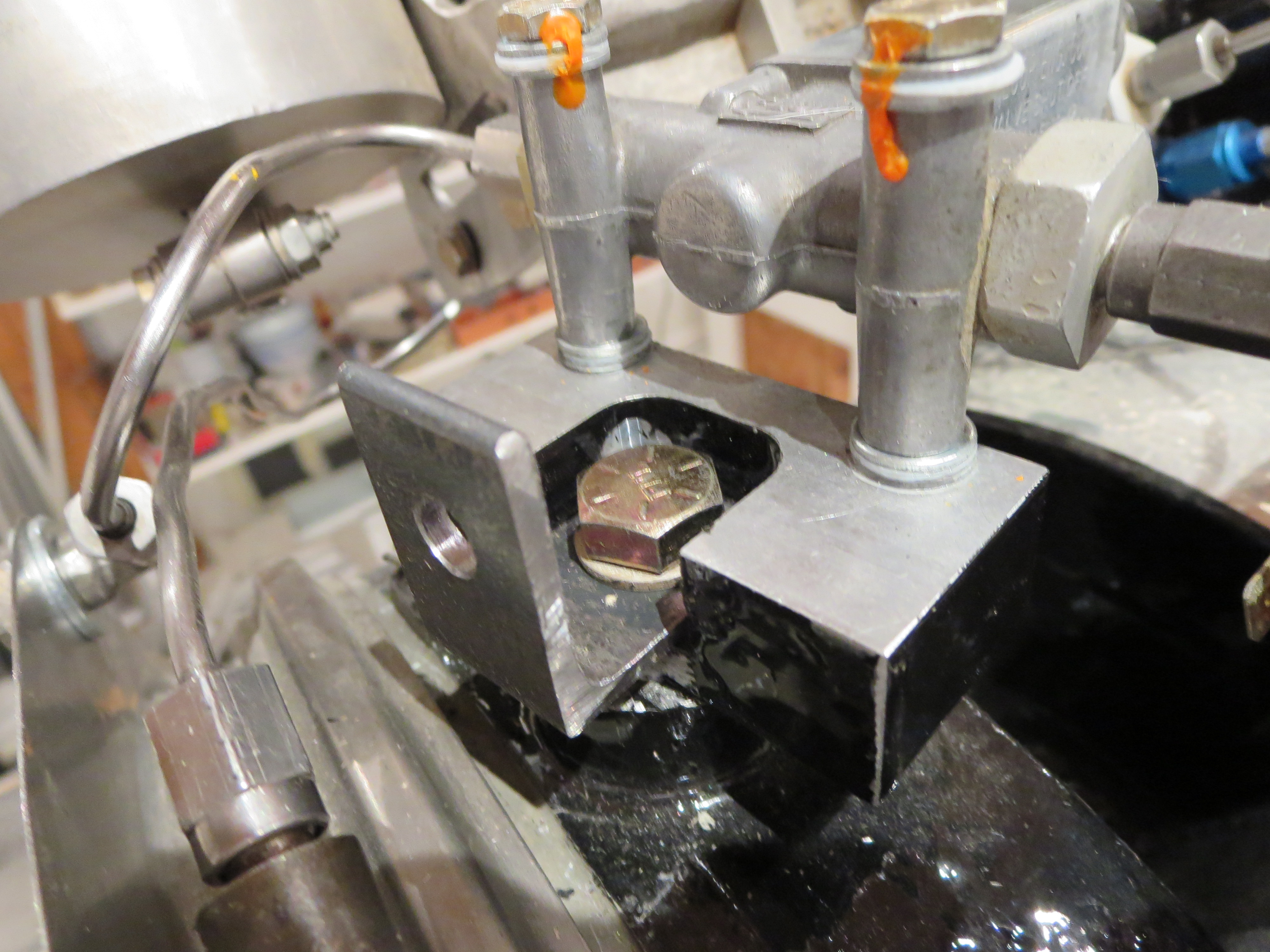

That's just some hardware store GR8 bolts and angle iron from Home Depot. I had forgotten just how nice steel is to work with. Drilled a bunch of holes since I do not know where the CG of the engine is. This way I can just hook on the closest balance point. If this were a permanent thing I would have used more and better mounting points, but it is a single-use, single-function item.
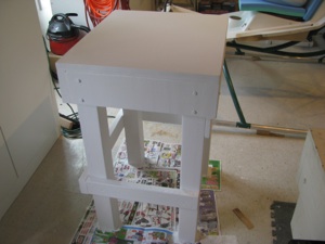
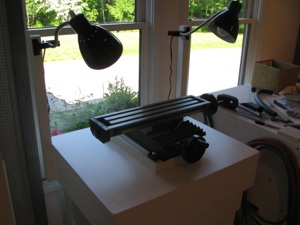
Shapeoko 2 CNC Router
For my birthday I got a Shapeoko CNC router. Shown is the basic stock configuration. I only purchased the mechanical kit (no motors or electronics). The first thing to do was assemble it as shown and then evaluate where it was strong and weak prior to modifications.
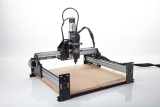
My goal with the machine is to be able to fabricate complex brackets out of (up to ) 1/4" Al plate. I thought about a real CNC mill, but was not willing to invest the time or cash at this point for a big machine. Turns out that was probably a good idea. This is a neat machine, but it may fall short of my goal. Still, it is a great way to learn CNC without a massive investment and to figure out a tool flow and develop experience that would be far more expensive to do with a bigger machine. I will ultimately end up probably with a CNC version of the Grizzly G0704, but that is a longer term thing.
Here is my own modified end product:

Modifications include:
1) Longer X and Y travel by 50% (up to 750mm from 500mm) doubling work surface area
2) Stiffening Y travel with mid-span brackets
3) Stiffening X by bracing dual extrusions together. Reduces torsional twist.
4) NEMA 24 motor upgrades on X and Y axes
6) Dewalt DW660 router for cutting. This thing is a beast. Very, very loud, though.
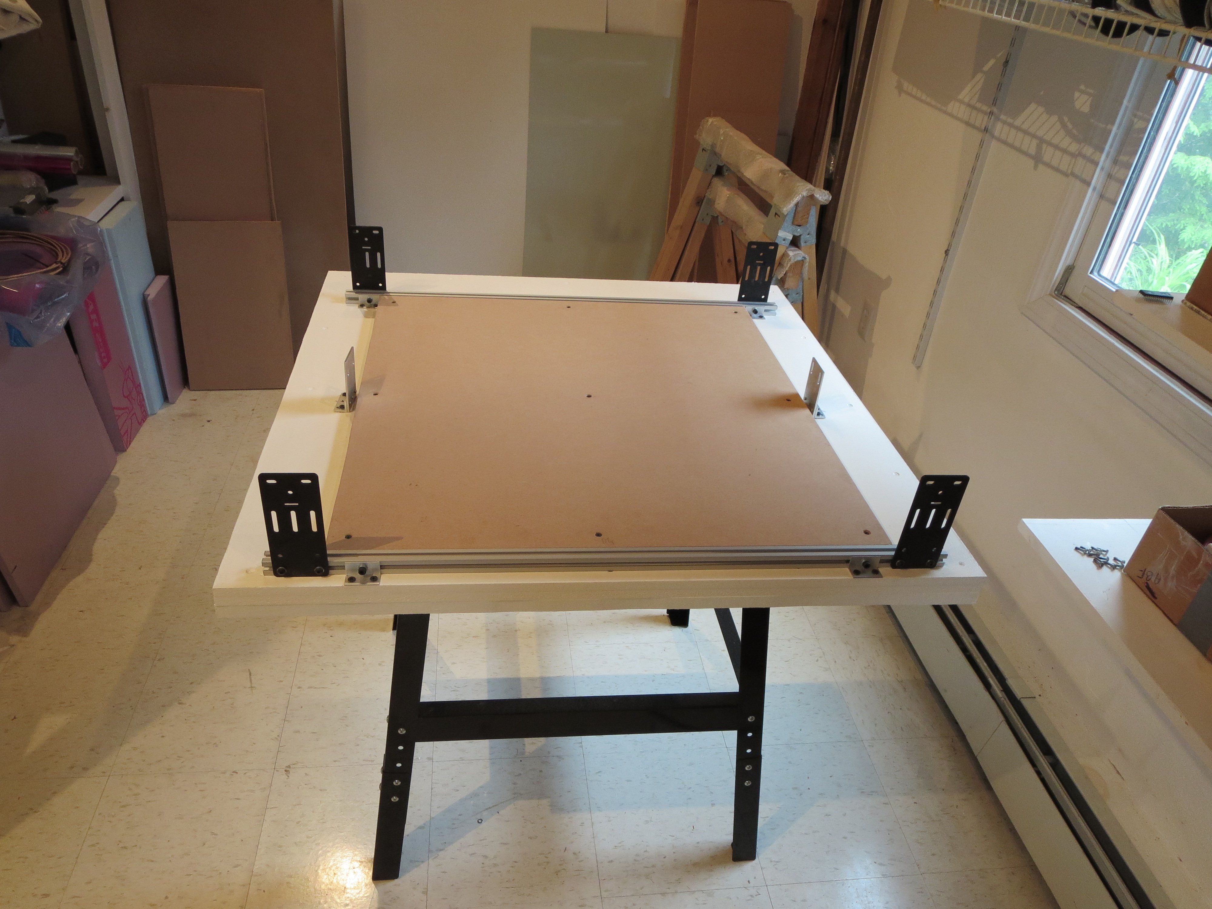
The table is a Harbor Freight $29 tool table. I buy less and less stuff from HF because of their marginal quality, but sometime they have just the thing. The base is layered MDF up to 1.75" think. The sheets are screwed and glued, but prior to that I shimmed them the best I could for flatness. The wasteboard is 0.75" thick.
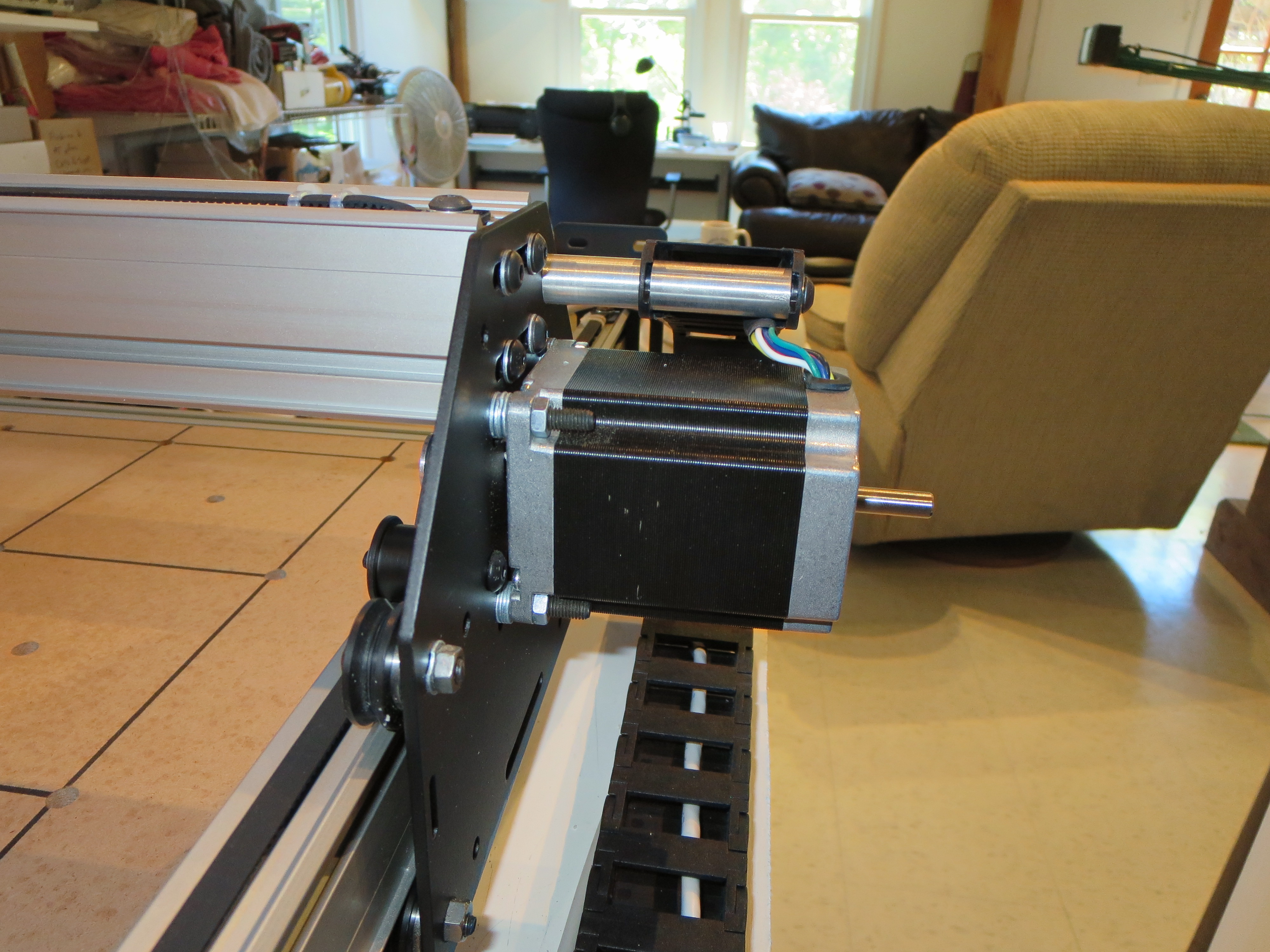
The Y-axis motors are NEMA 24 upgrades. a little shimming and careful attention to build order in order to fit it all together. Some quick lathed mounts for the drag chain.
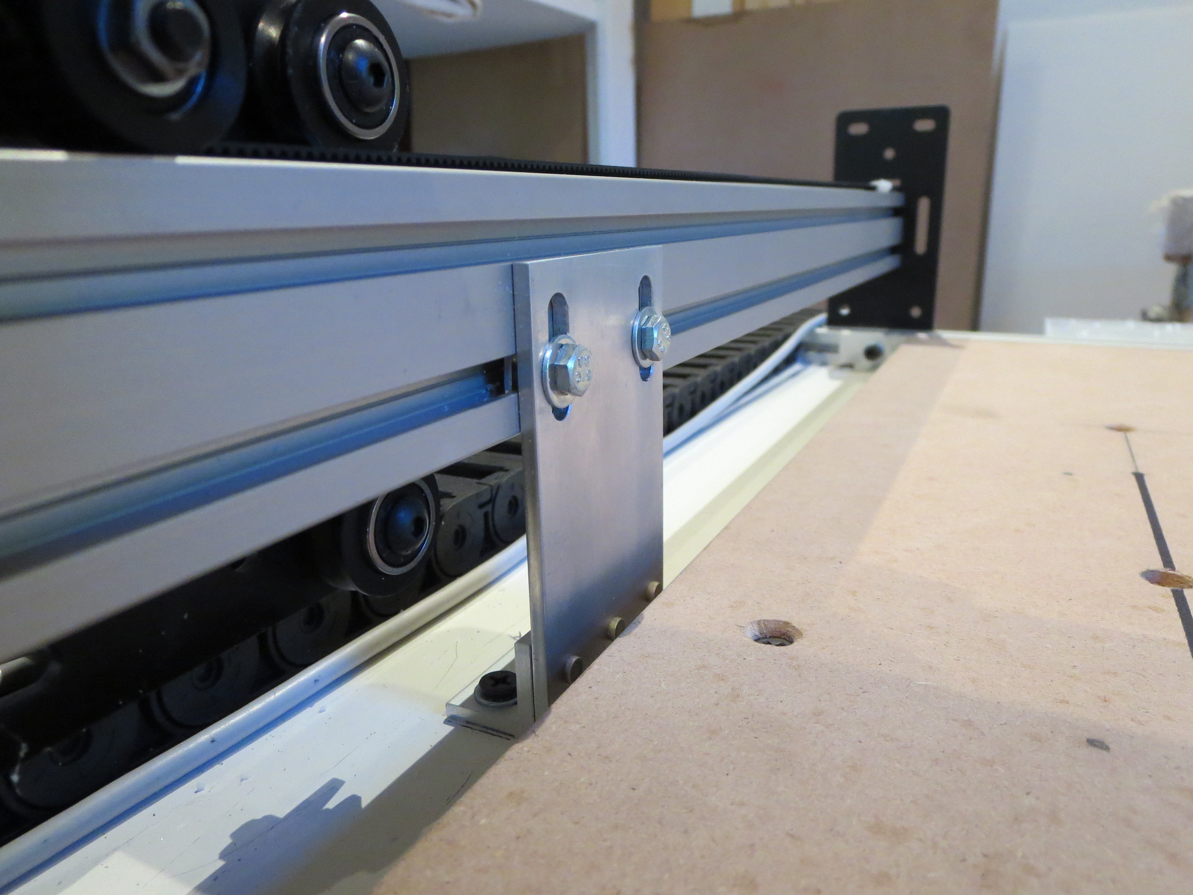 Whipped up a couple of braces for Y-axis support. Simple angle and plate machined up on my mill. Riveted with aircraft project leftovers. Nice to have the tools and materials at hand. The longer Y-Axis needs support in the middle and this also keeps the fore and aft direction from flexing.
 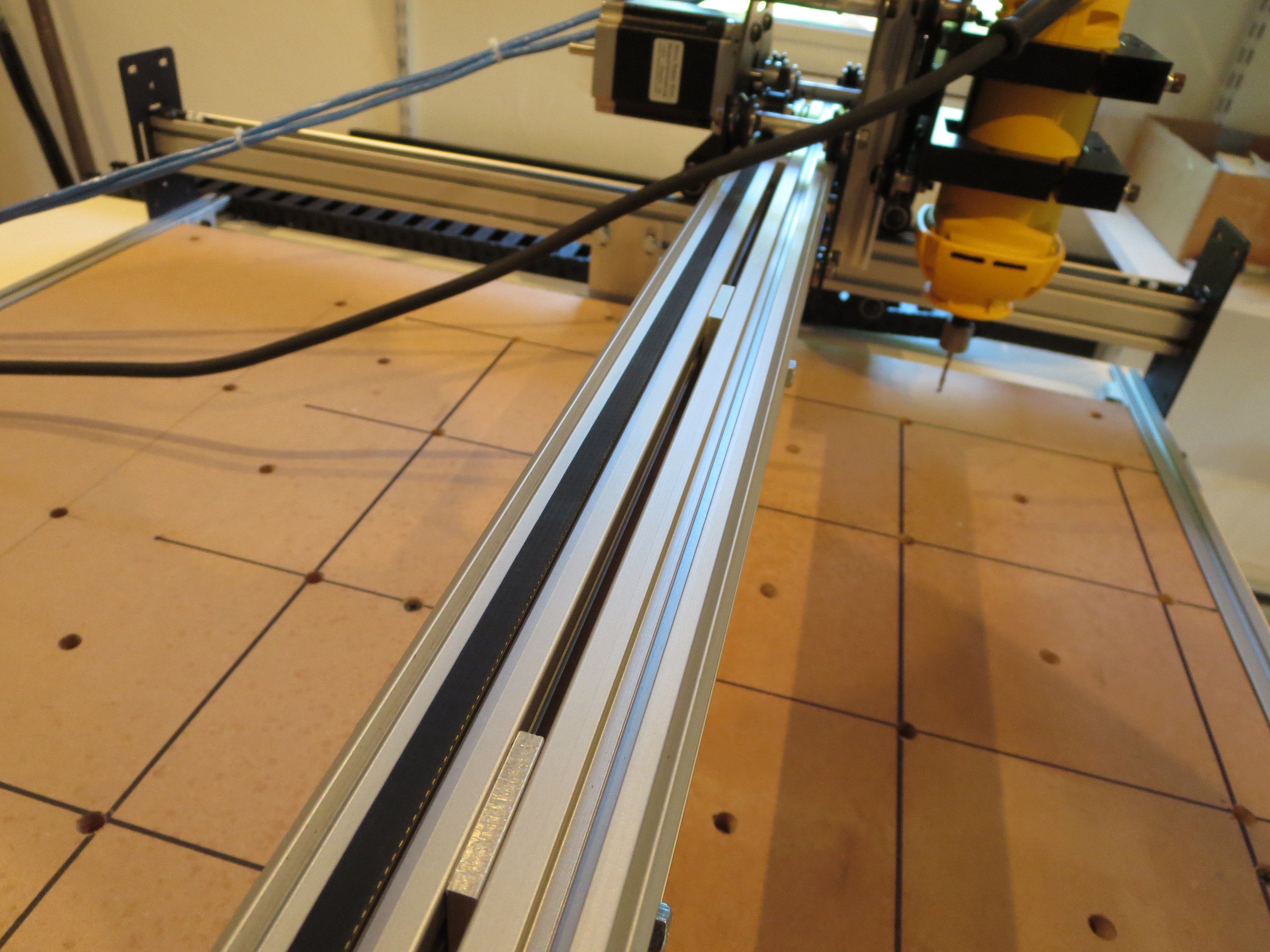 The stock configuration only has the pair of extrusions only attached at the ends. To keep the extrusions from flexing relative to each other, I first built up the carriage, fitted it, and measured and fabricated proper thickness shims to affix them together. This really stiffened up the carriage in the vertical dimension.
It is important to build it up before measuring for the shims as the width can't be determined accurately until the thing is fit together to find the "natural" width of the carriage rollers.
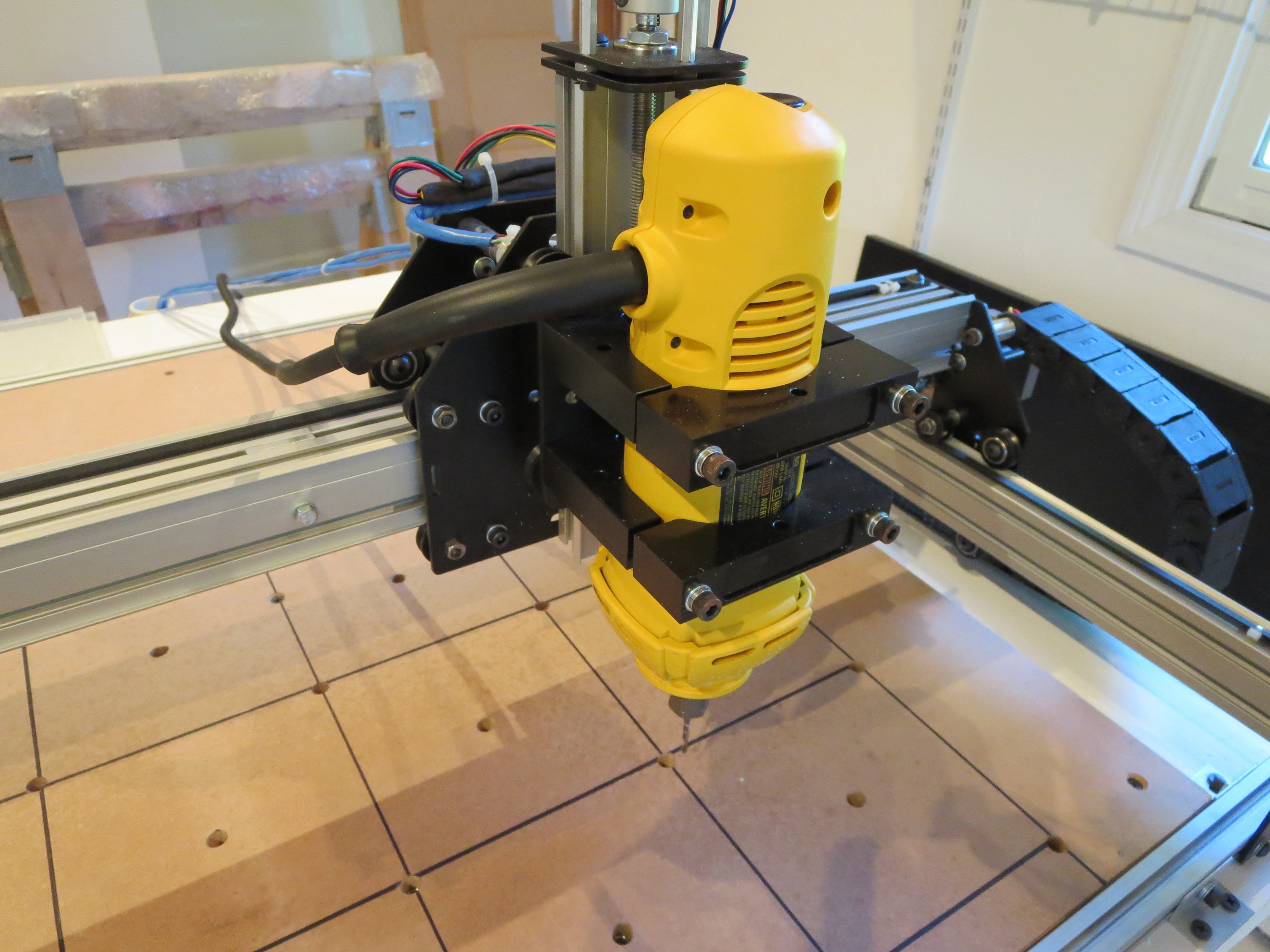
The DW660 router is much heavier than the stock spindle and needs good bracing. The wires from the X-axis and router will be dressed better when I get a smaller drag chain. Works for now.
Electronics bolted to MDF plate in the back of the machine. Protected by the table top, so I didn't feel the need to make a full case.
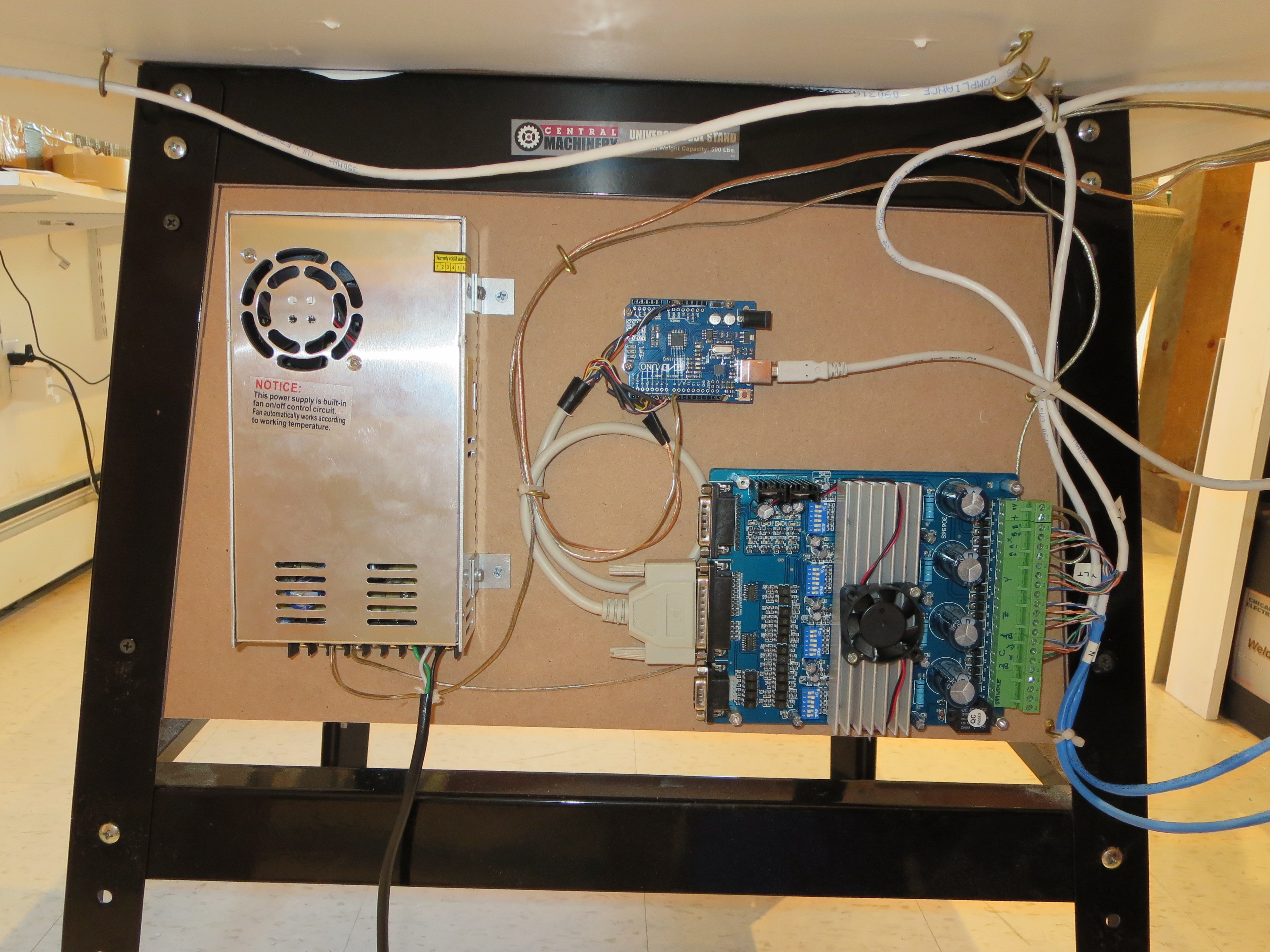
The motors and controller were purchased off ebay for about $200 from wantaimotor.com. Wow. Lots of capability for short money. It all worked, but was not at ALL documented and the limited docs that were provided were WRONG. A lot of web searching and reverse engineering needed to figure out pinouts, voltage levels, and controls. The controller is an Arduio UNO ($10 on ebay) running GRBL. Doesn't get much cheaper for CNC control.
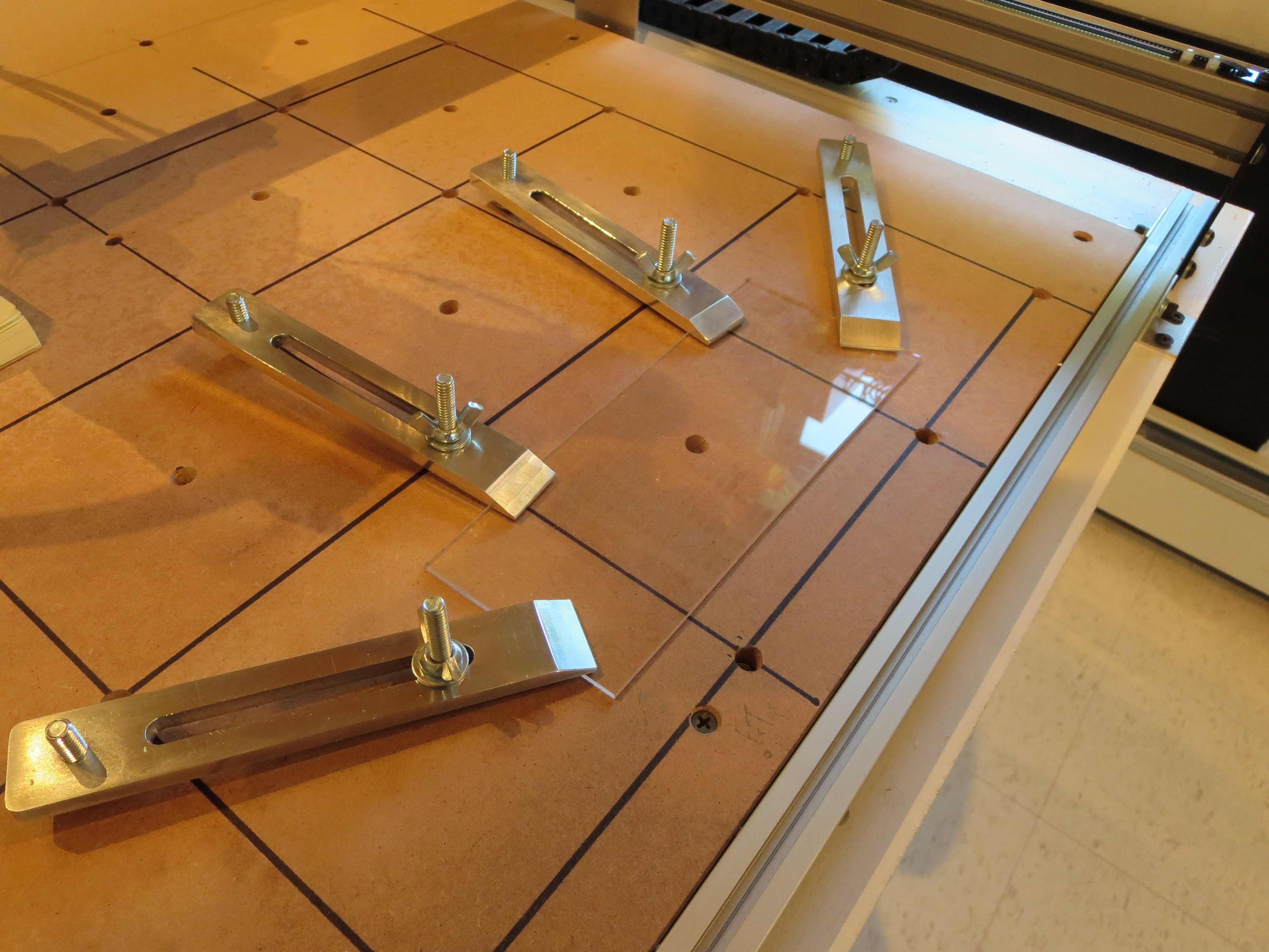 Made some hold-down brackets on the mill. The washboard has an array of T-Nuts installed flush from the bottom. Screw the threaded rod from the top into the wastboard, slip over the hold-down, adjust the carriage bolts for the right angle, and then spin the wing nuts to tighten. Simple and effective.
My tool flow is:
Spaceclaim (running under Windows VM on my MAC) - 3D and 2D modeling of parts and brackets. Export is DXF (2D) or STL (3D)
or
Adobe Illustrator (running OS-X on MAC ) for art drawings and 2-D text for engraving. Export is DXF
CAMBAM (running on Windows-VM on MAC)for tool path generation. http://www.cambam.info
Universal G-Code sender (running OS-X on MAC) for controlling the machine (free)
So all-in I had to buy CAMBAM for about $180. The rest was free or something I had already.
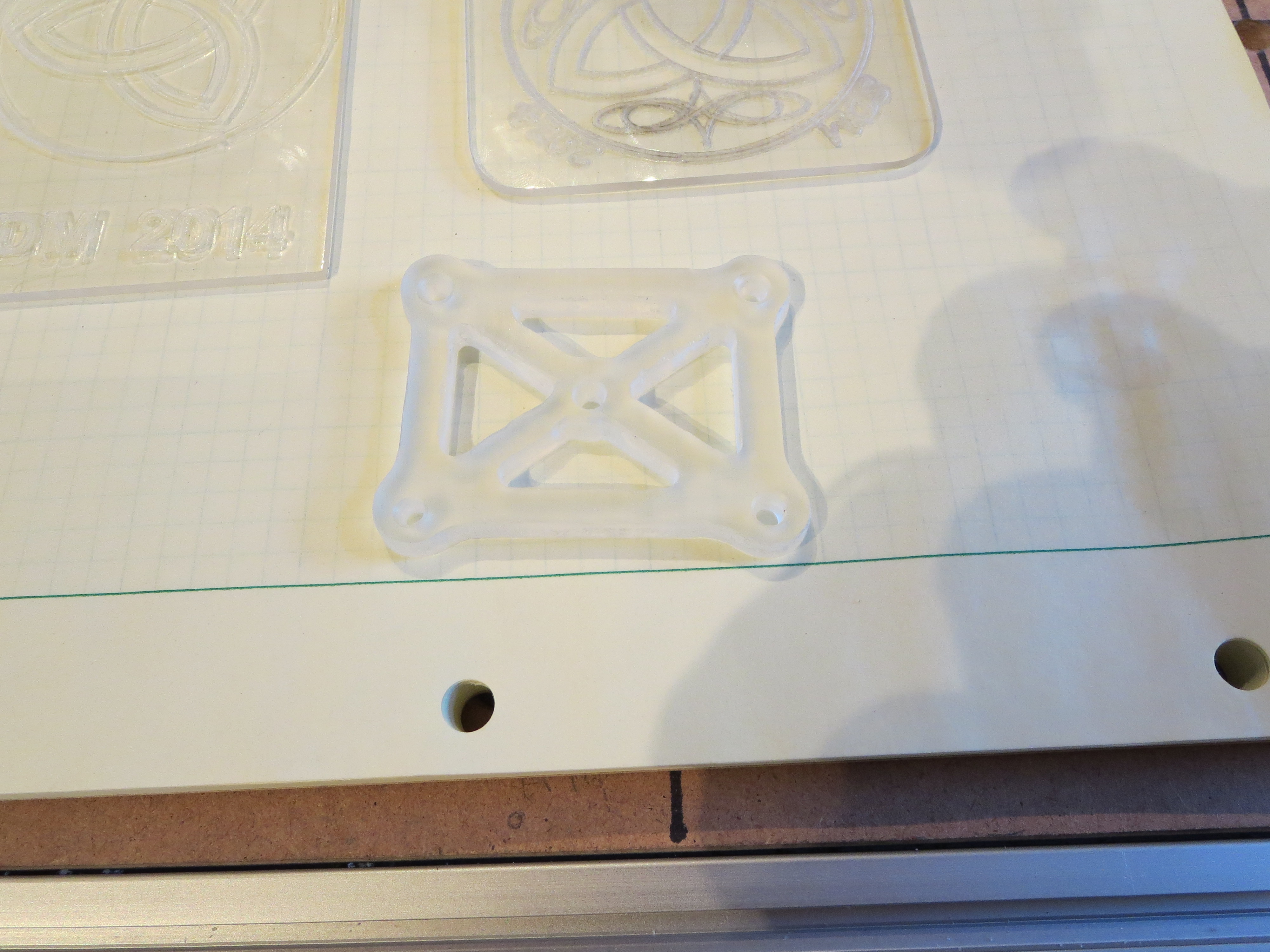
Here are some early examples in some plexi scraps I had lying around. Obviously I have to work on tooling and feeds for better results. Cutting plexi is weird in that you have to be careful. If you cut too fast it "fragments" at the cutter. Too slowly and the plexi melts and build up on the cutter, affecting the accuracy of the line.
Conclusions:
For engraving this will be great. For milling soft stuff it's probably fine - haven't done much there yet. For aluminum it is weak. It is just not stiff or strong enough, even with my modifications, to accurately cut thicker plate. I will experiment with speeds and tooling to see if something acceptable can be determined.
The machine works great for what it is. I can see perhaps cutting outlines and lightening hold in brackets, then moving the piece to the mill for accurate cutting of holes. It is very satisfying to see it run repeatably and position accurately; hypnotic almost. I have learned a lot and when I do get to the construction of a man-sized mill it will go much more smoothly. I have purchased a 2W laser from ebay to try my hand at laser etching. That'll add a whole new level of danger to the shop.
My total investment is about $700 and a month and a half of weekend spare time. I think of it as a self-taught course in CNC machining. From that perspective it seems pretty cost effective. It's now just another tool in the shop. Like the Mill - it was a project that once done will become a very useful tool. Time to get back to the Helicycle.
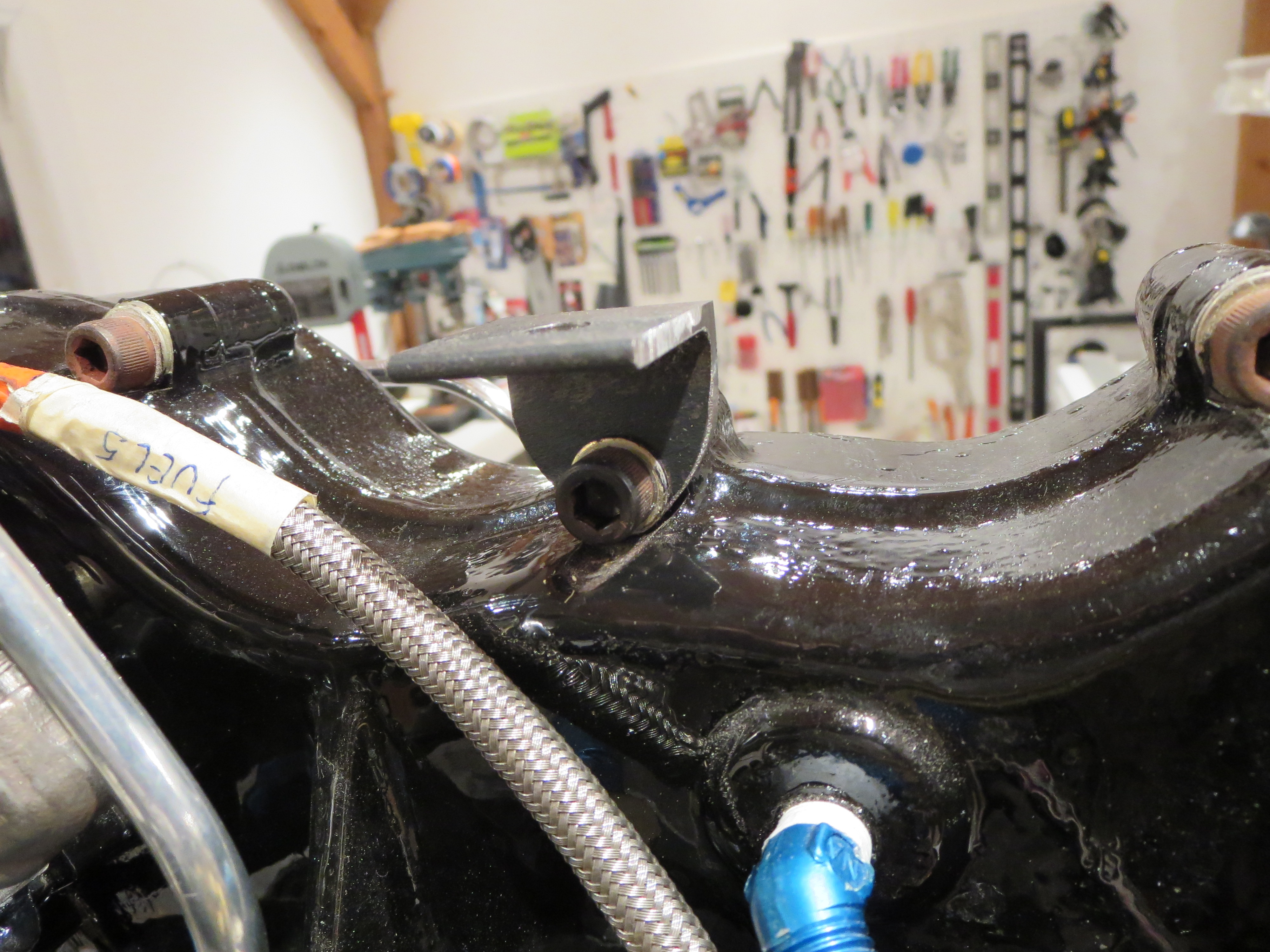
Final Pedal Mounting
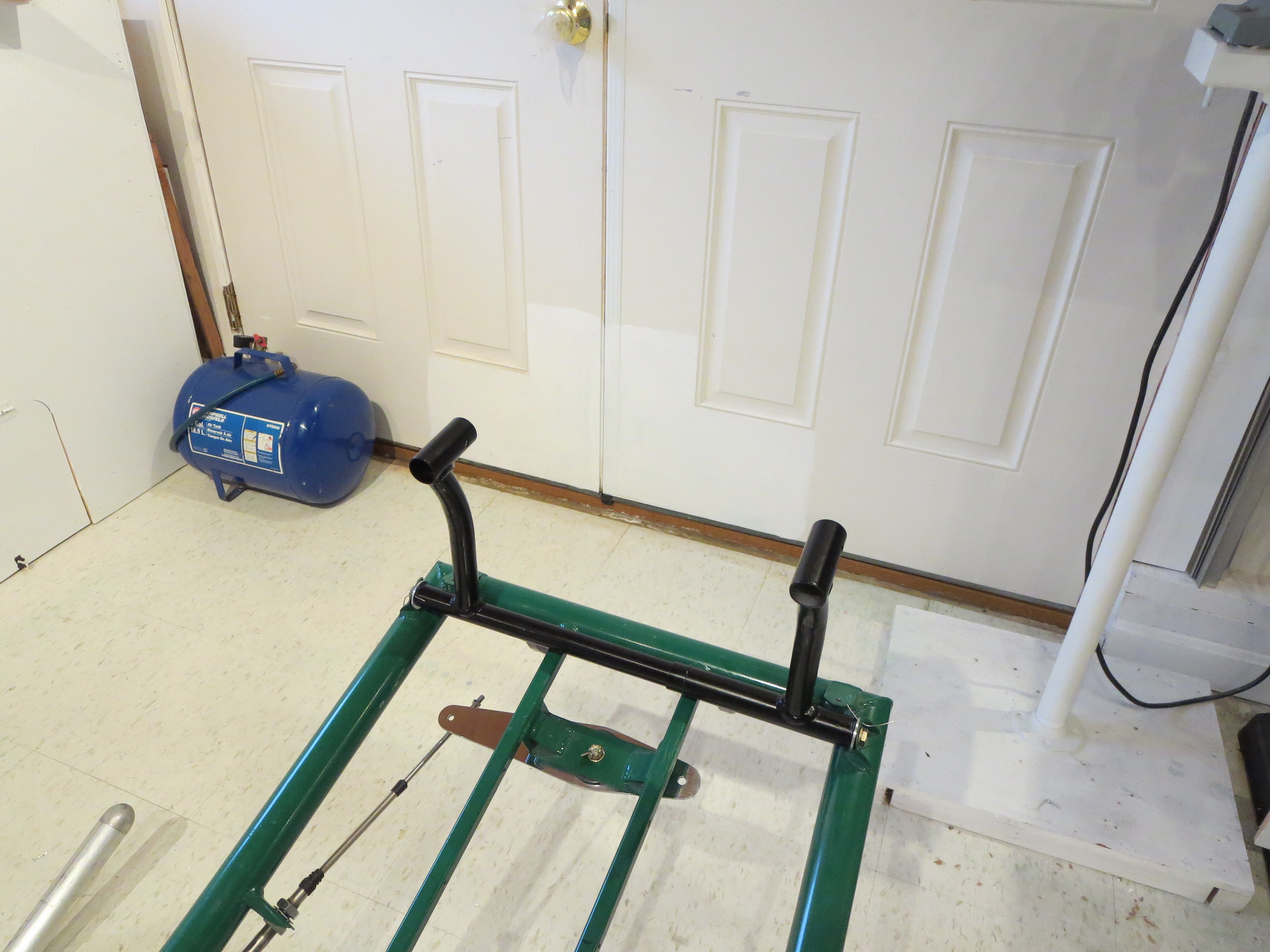
I went to FINAL mount the TR pedals as it is time to start placing some things on the ship for the LAST time now. When I went to snug the bolts up it all bound up and was very stiff. Not good. Controls are supposed to have some damping, but should be butter smooth with no stiction.
After staring at it for a few minutes it became apparent that when the AL bushings are snugged up, they get pulled against the welded steel tabs that mount them to the frame and those tabs are not perfectly square with the mate on the other side of the frame for the opposing bushing. That "tilts" the bushings and cause them to bind in the tube.
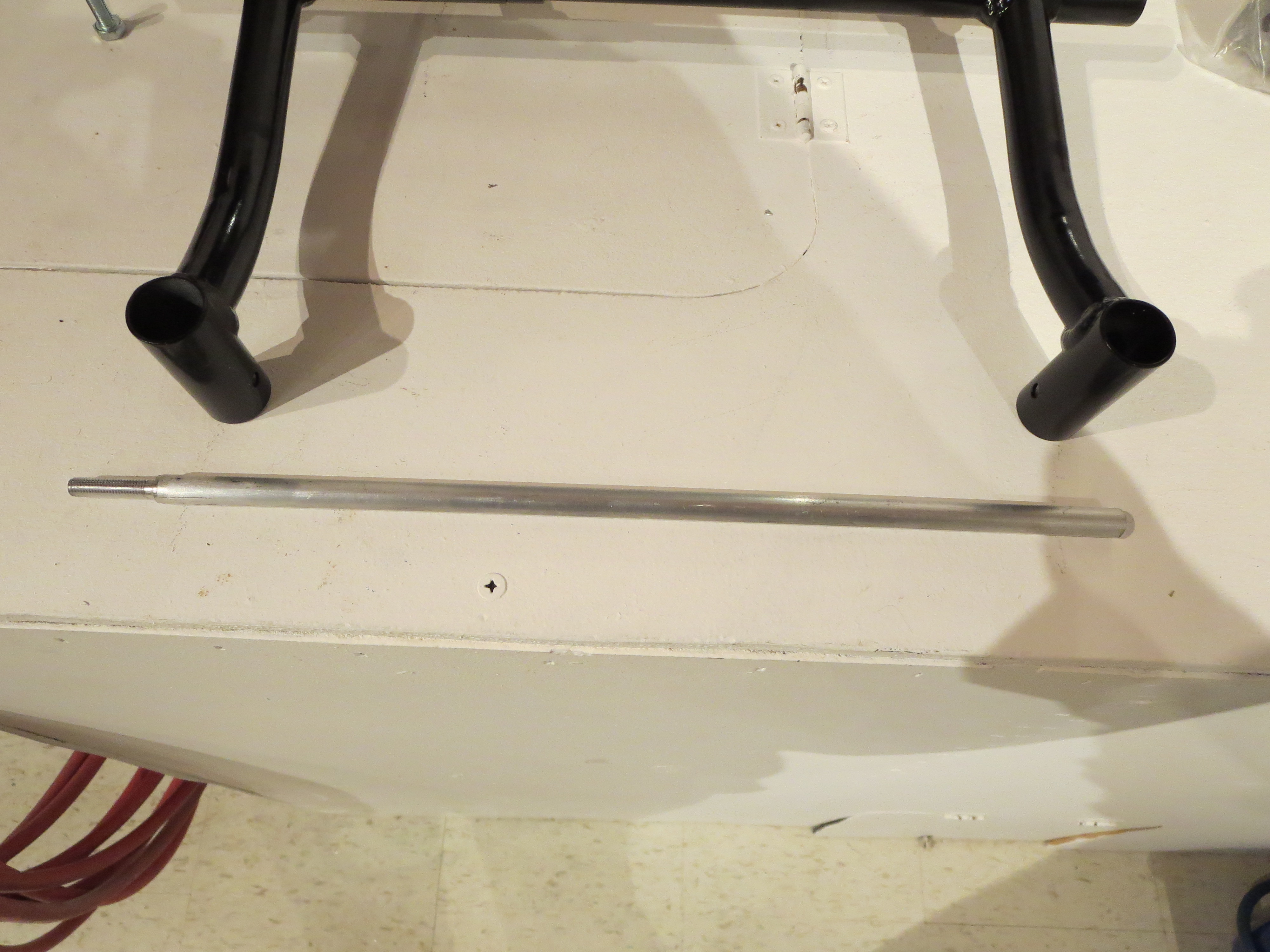
No problem. I have all these machine tools - time to put them to use. I lathed down and threaded an aluminum rod that was the appropriate length to thread into the bushing to "point" to where the alignment was on the opposite side.
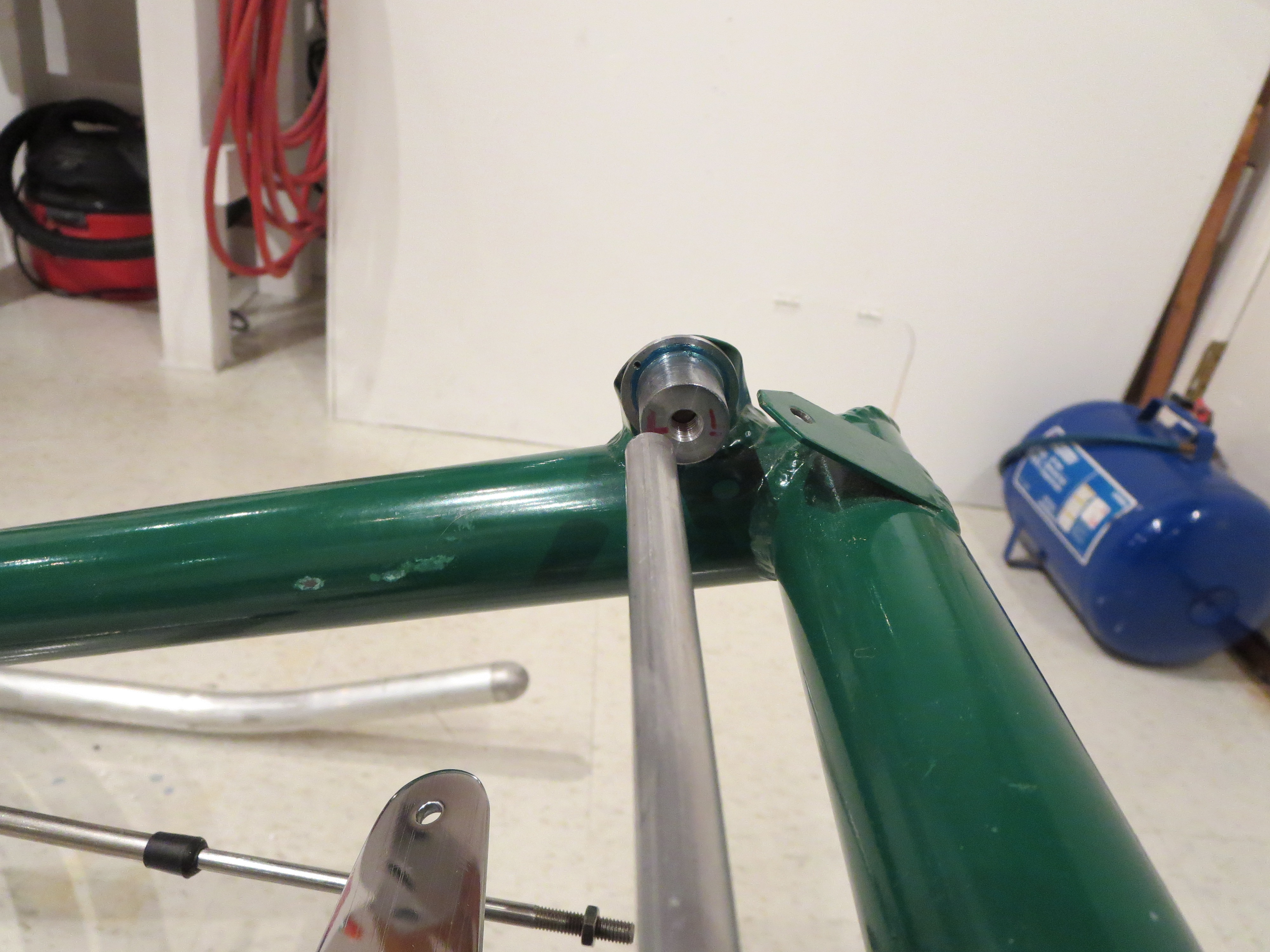
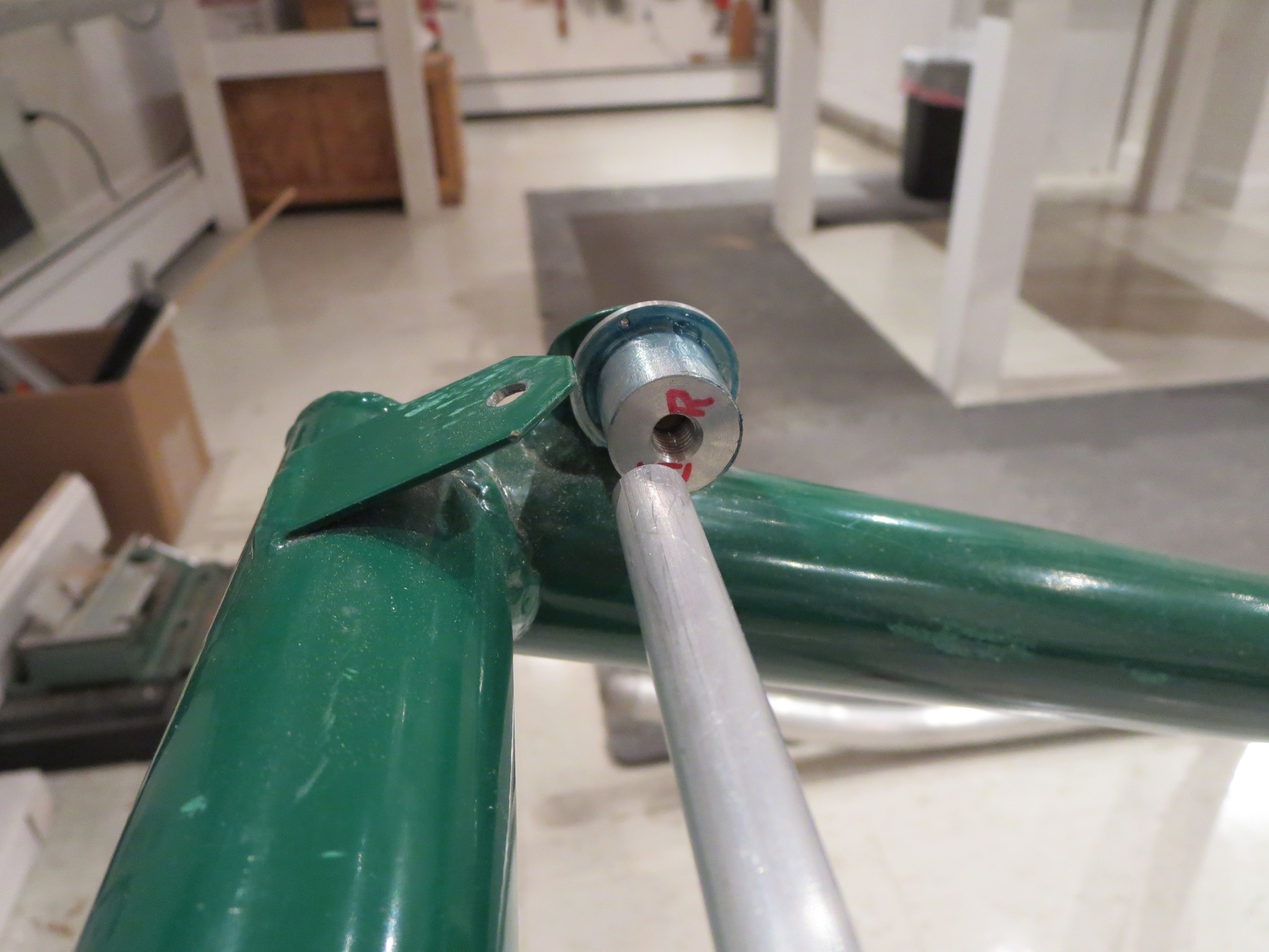
With those very evident visual cues it was very easy to tweak the mounting tabs (it didn't take much) to bring everything into nearly perfect alignment.
Amazing how such a small change resulted in such a large difference in the feel and operation of the pedals. Greased up, snugged up, Safety wired. The first permanent moving part. Lots to follow in a short period. Nice.
DVD Index
I finally got around to indexing the contents of the DVDs. At this point I need to find certain things quickly. All the DVDs have been loaded onto my iPad so I can reference them quickly in the shop. Also shown is the order in which the items should be completed for final assembly.
| DVD Contents | ||||
| DVD | Group | Sequence | Subject | SDM Order |
| 1 | 1,2 | 1 | Full and Half Door Construction | |
| 1 | 1,2 | 2 | General Construction and Fitting Landing Gear | 1 |
| 1 | 1,2 | 3 | Cabin and Trim Fins- Floor Pan, Pod, Cabin, Windscreen, chin window | 2 |
| 1 | 1,2 | 4 | Cabin and Trim Fins continued - Trim fins and mounting. | 3 |
| 2 | 3 | 1 | Fuel System | 4 |
| 2 | 3 | 2 | Direction Controls, Cyclic Controls | 5 |
| 2 | 3 | 3 | Fitting of Controls to Ship | 6 |
| 3 | 4,5 | 1 | Main Transmission Fitting and Lift Strut | 7 |
| 3 | 4,5 | 2 | Tail Rotor shaft construction. TR gearbox. Tailrotor fitting. | 10 |
| 3 | 4,5 | 3 | Tailrotor balance and general information about design | 8 |
| 3 | 4,5 | 4 | Tailrotor gearbox mountings and alignment | 9 |
| 3 | 4,5 | 5 | Control rod fitting and swashplate alignment. | 15 |
| 4 | 9 | 1 | Turbine engine installation and control information | 12 |
| 4 | 9 | 2 | Governor construction and installation notes. | 13 |
| 4 | 9 | 3 | Turbine plumbing and fittings. Clutch Assembly. | 11 |
| 4 | 9 | 4 | Motor mount fitting and alignment | 14 |
| 5 | 6,7 | 1 | Rotor head fitting. | 16 |
| 5 | 6,7 | 2 | Rotor Blade Doubler Bonding | 17 |
| 5 | 6,7 | 3 | Rotor doubler continued and end caps. | 18 |
| 5 | ,67 | 4 | Rotor mounting and balancing. | 19 |
| 6 | 8 | 1 | Battery Box Mounting and general wiring information | 20 |
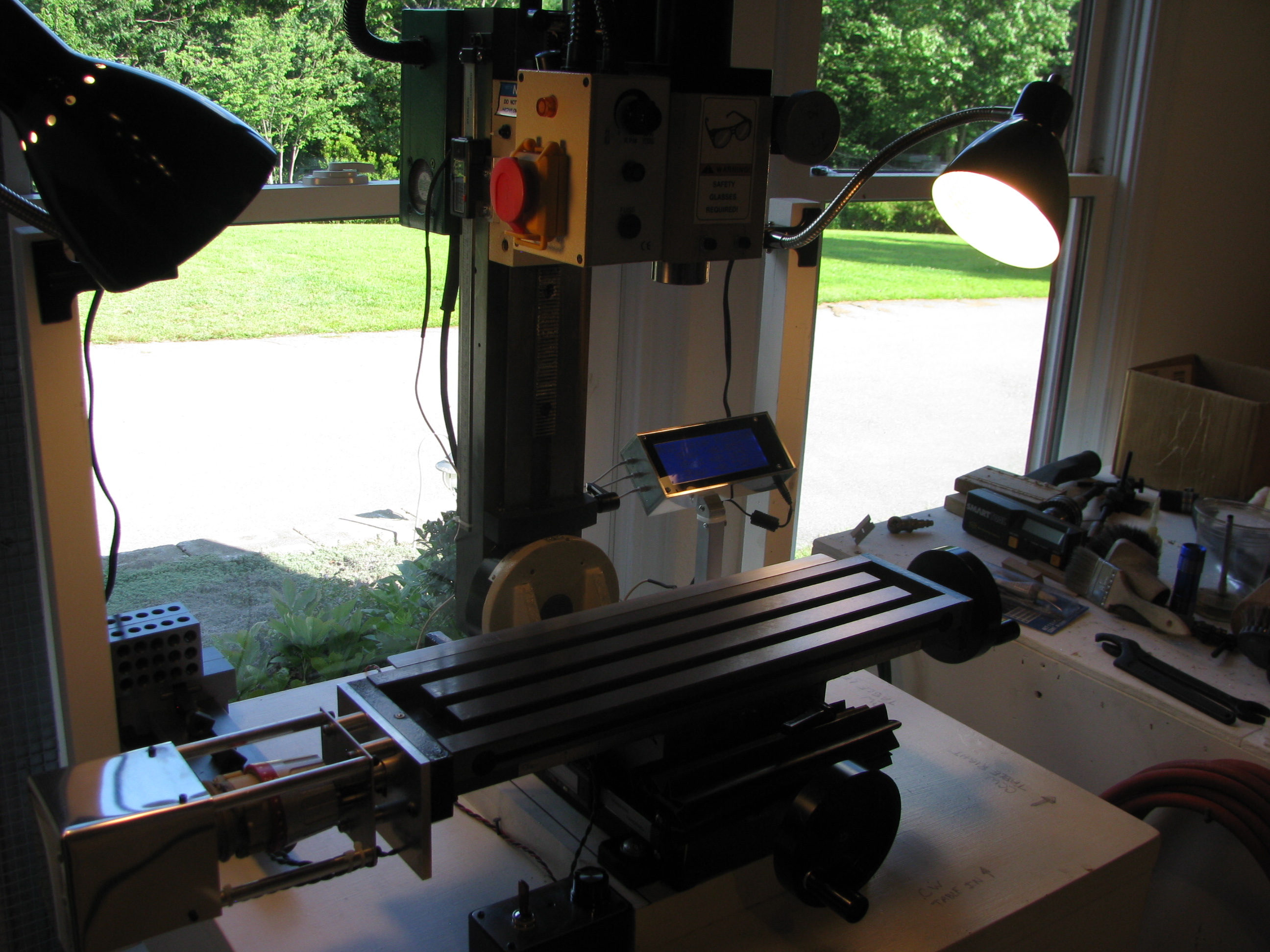
Mill DRO Design & Build
Clearly an accurate digital readout of the X, Y and Z-positions of the table and mill head will make jobs go much faster.
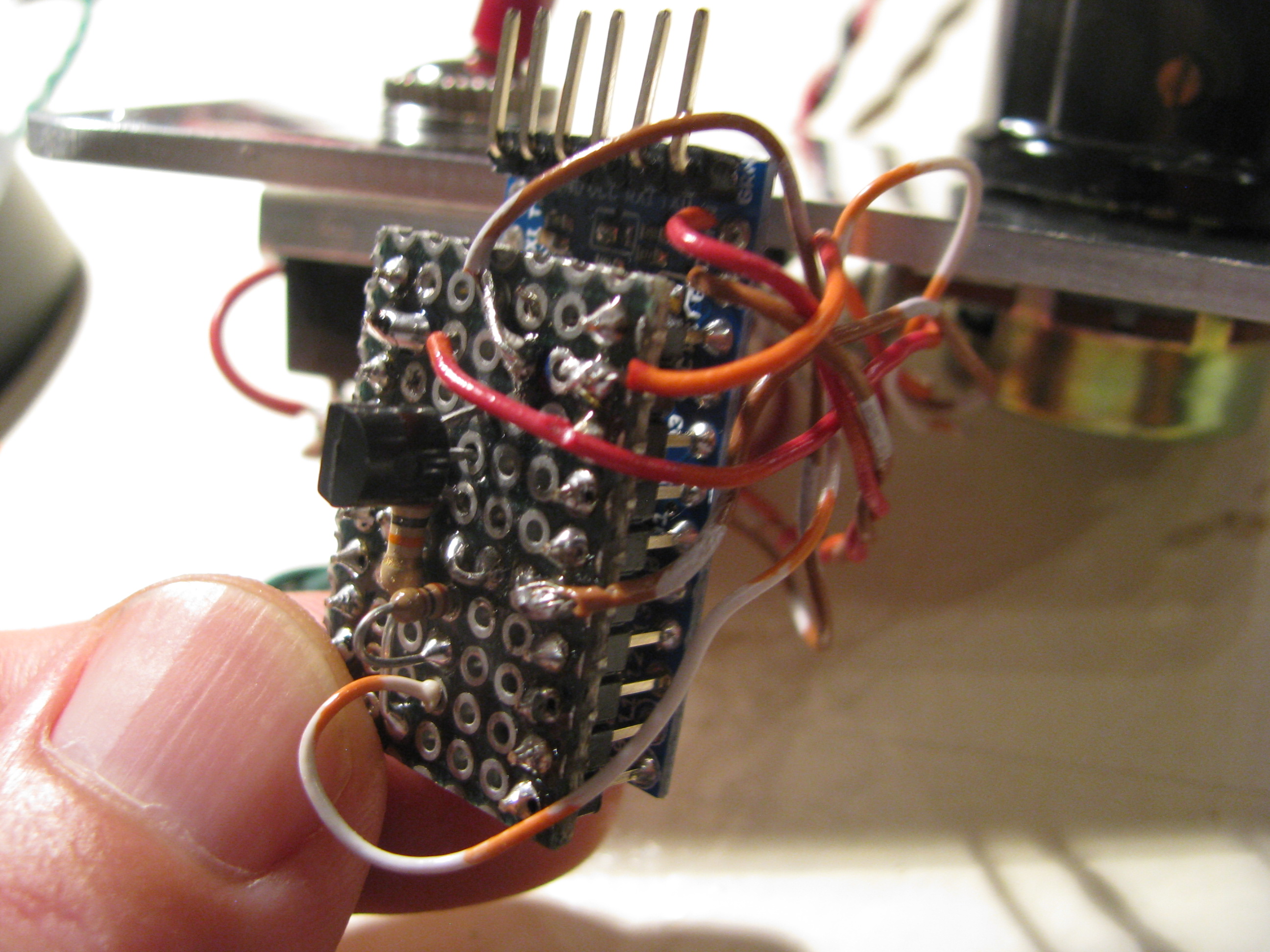
I purchased 2x12” and 1x8” digital caliper mechanisms off eBay for $24 for the 12” and $18 for the 8” respectively. I have read about various folks interfacing to those and hooked the interface signals up to a scope and observed and played around until I figured out exactly the protocol coming over the interface ports from the calipers.
For the ones I purchased the protocol seems slightly different than that measured by others. In my case the value output over the interface is simply a hex representation of the position in whatever units are selected (mm or in). One of the bits indicates the sign (it is not true twos complement), and another bit indicates the 0.0005” indication.
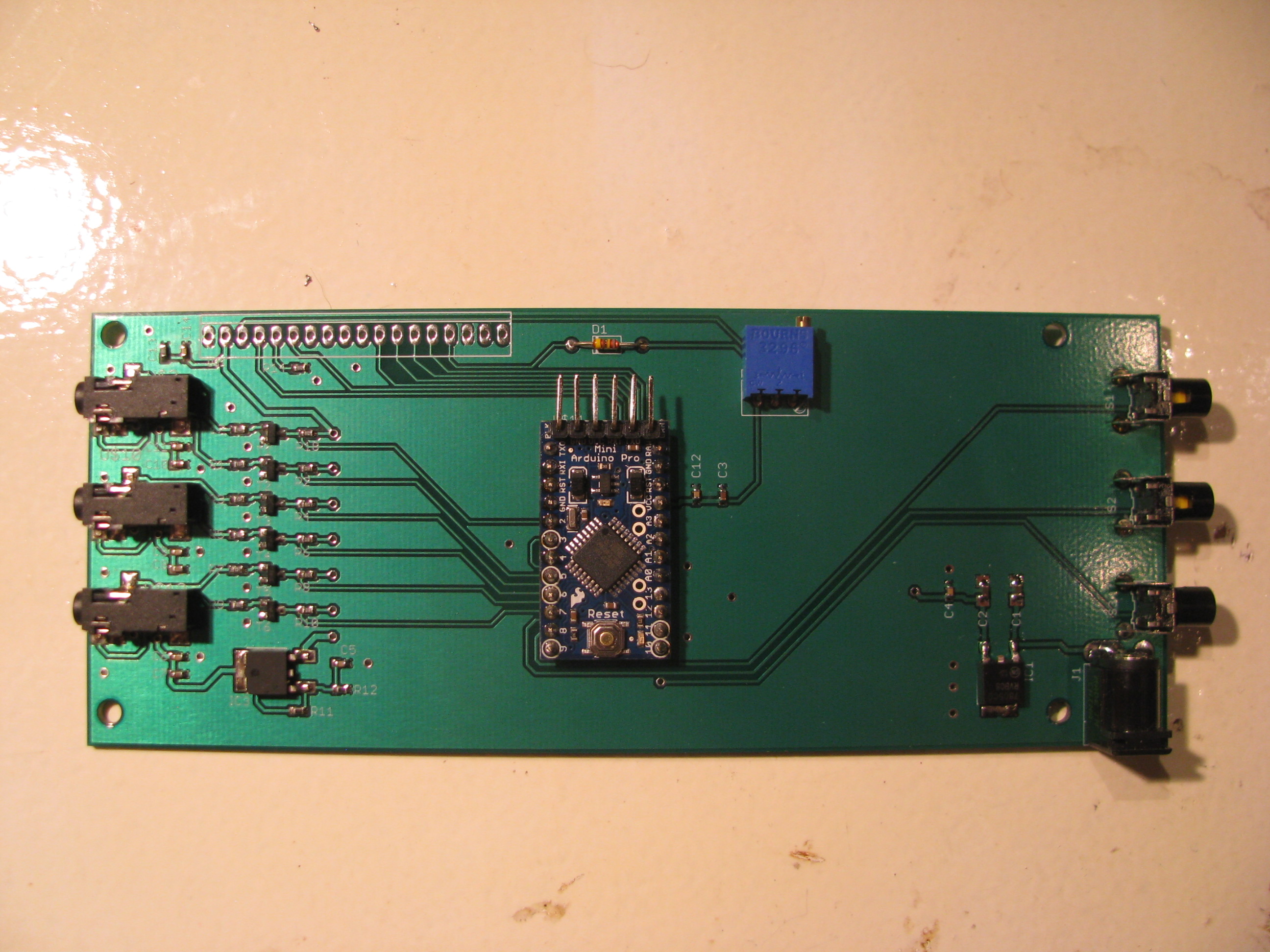
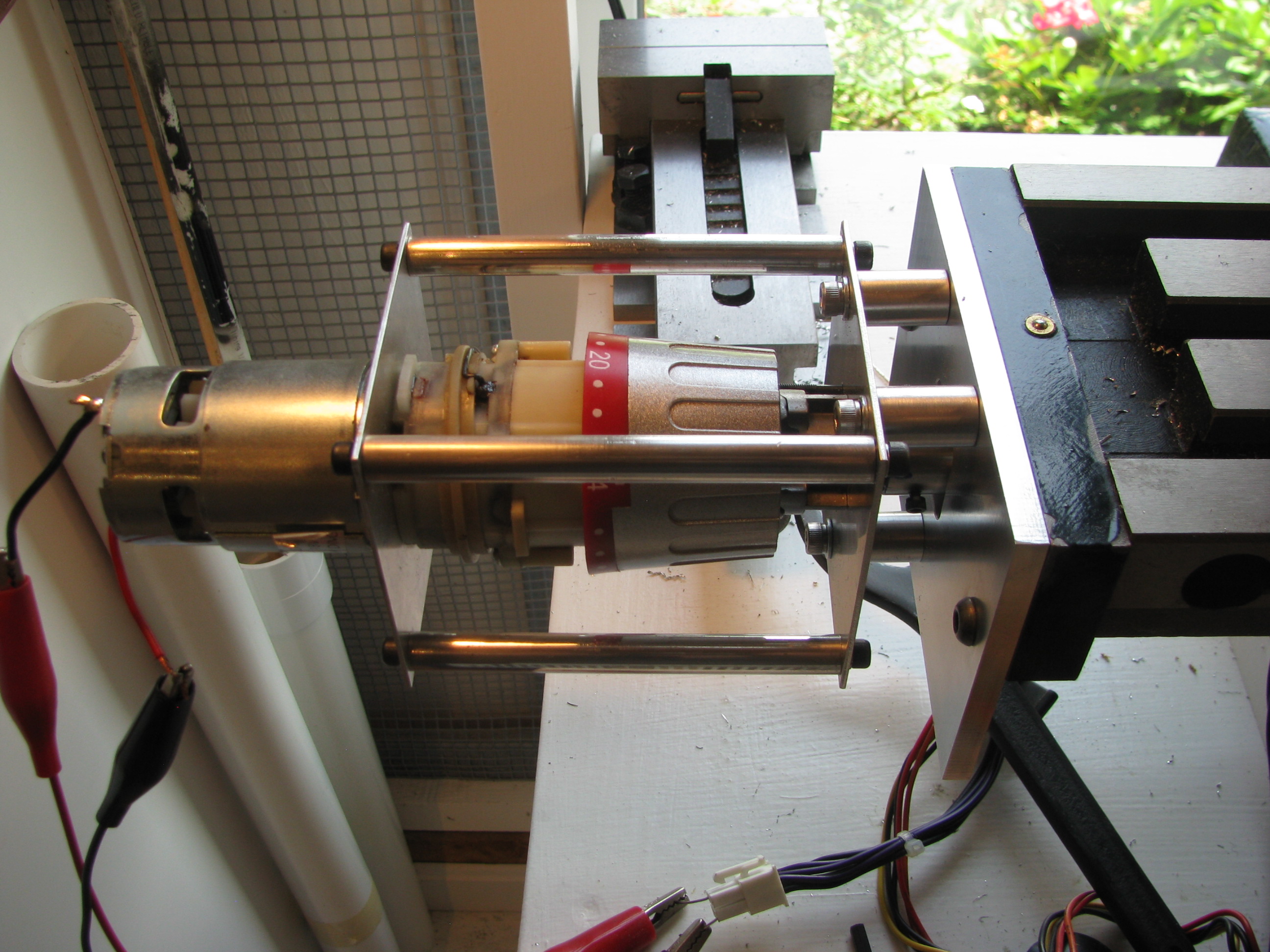
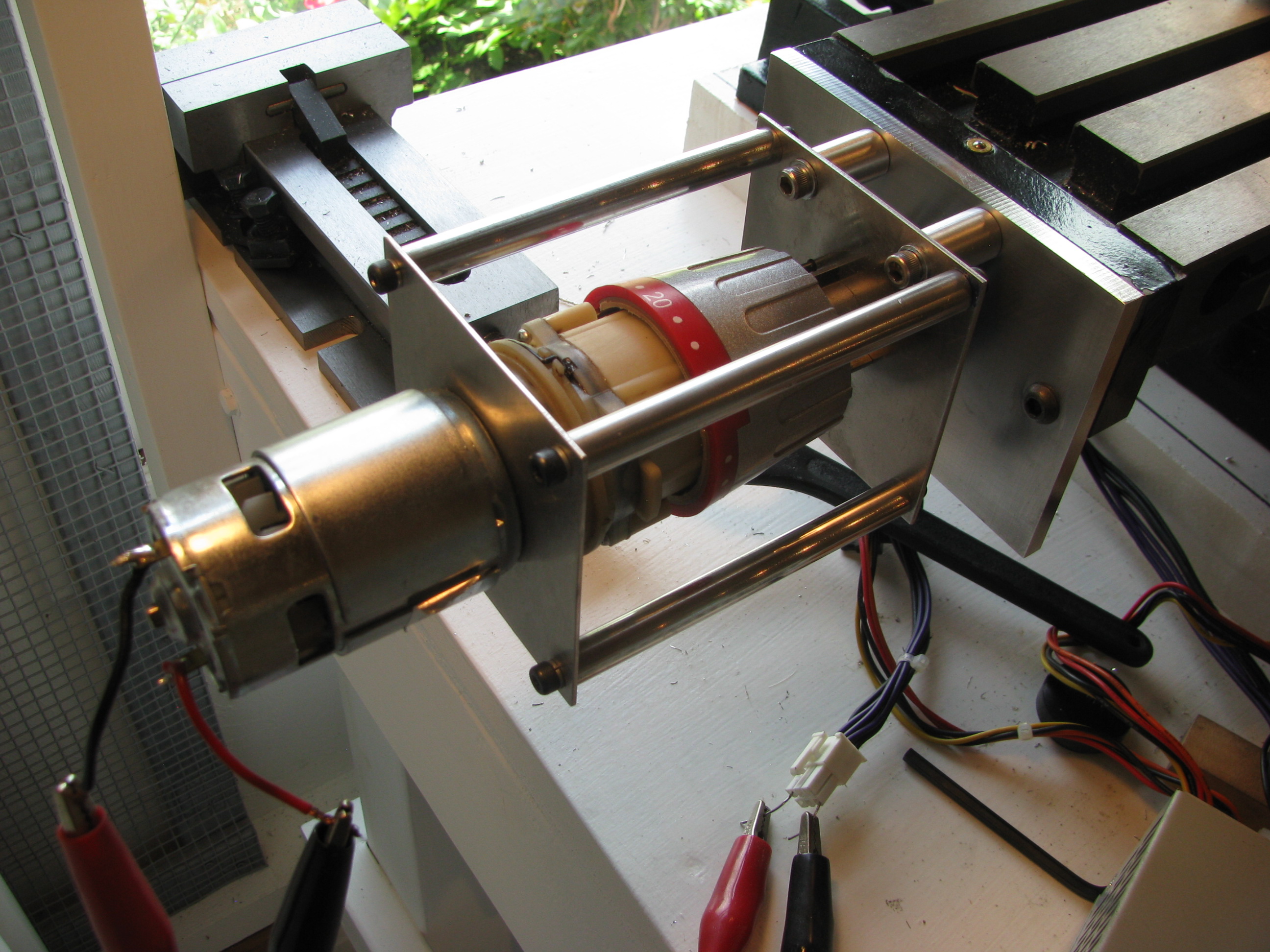
I whipped up a circuit to convert the voltage levels and wrote code to read the three values with an Arduino (that’s a ProMini in the center). I soldered the wires from 3 cellphone headsets (4-pin 3.5mm plugs with very, very fine flexible wires) to the caliper ports. The complete headsets were $0.99 each on eBay, which is cheaper than it would have been to buy connectors and cable and make my own. There’s $7 of buttons, connectors, passives, transistors, and regulators from Digikey rounding out the B.O.M.
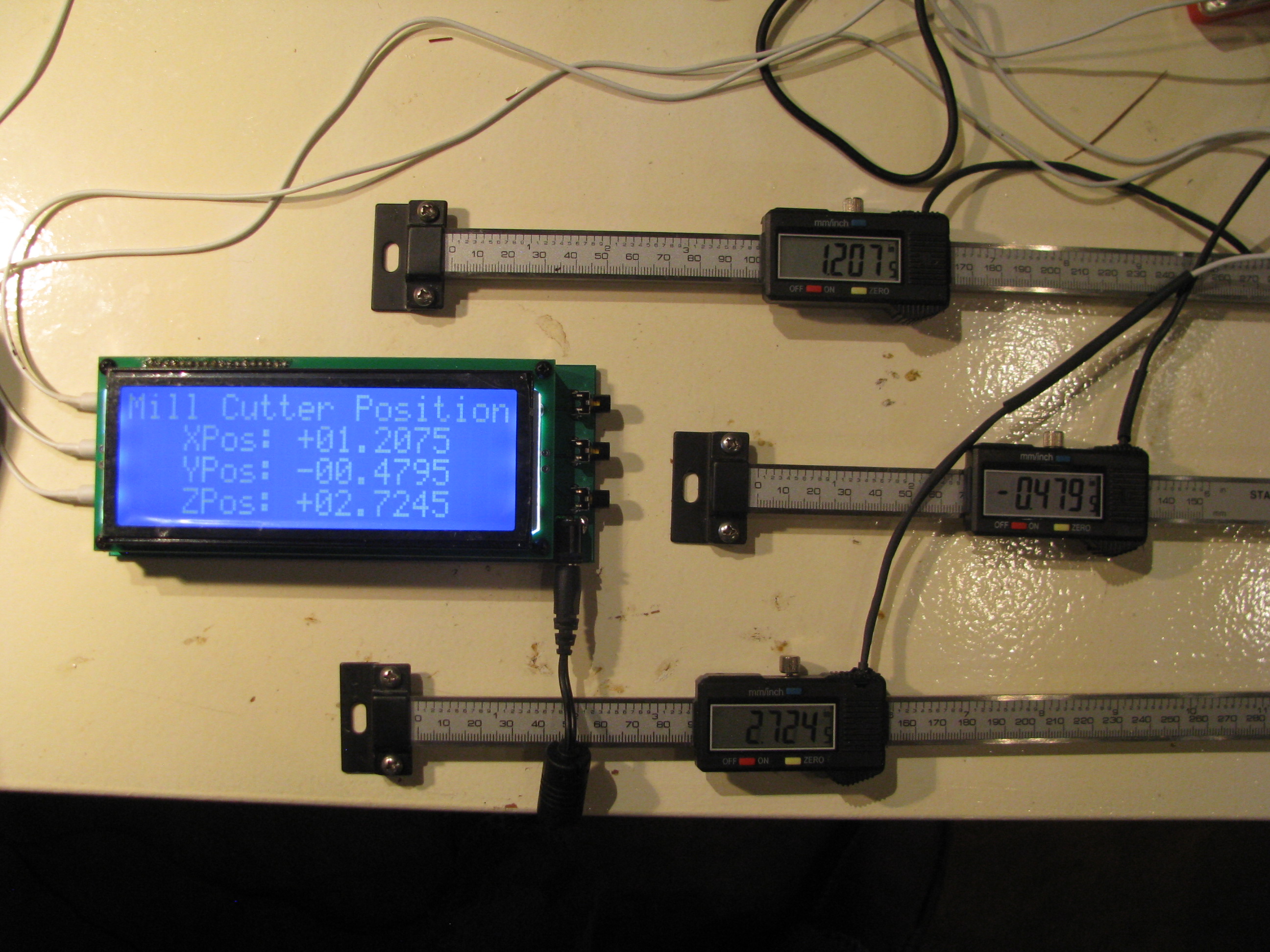
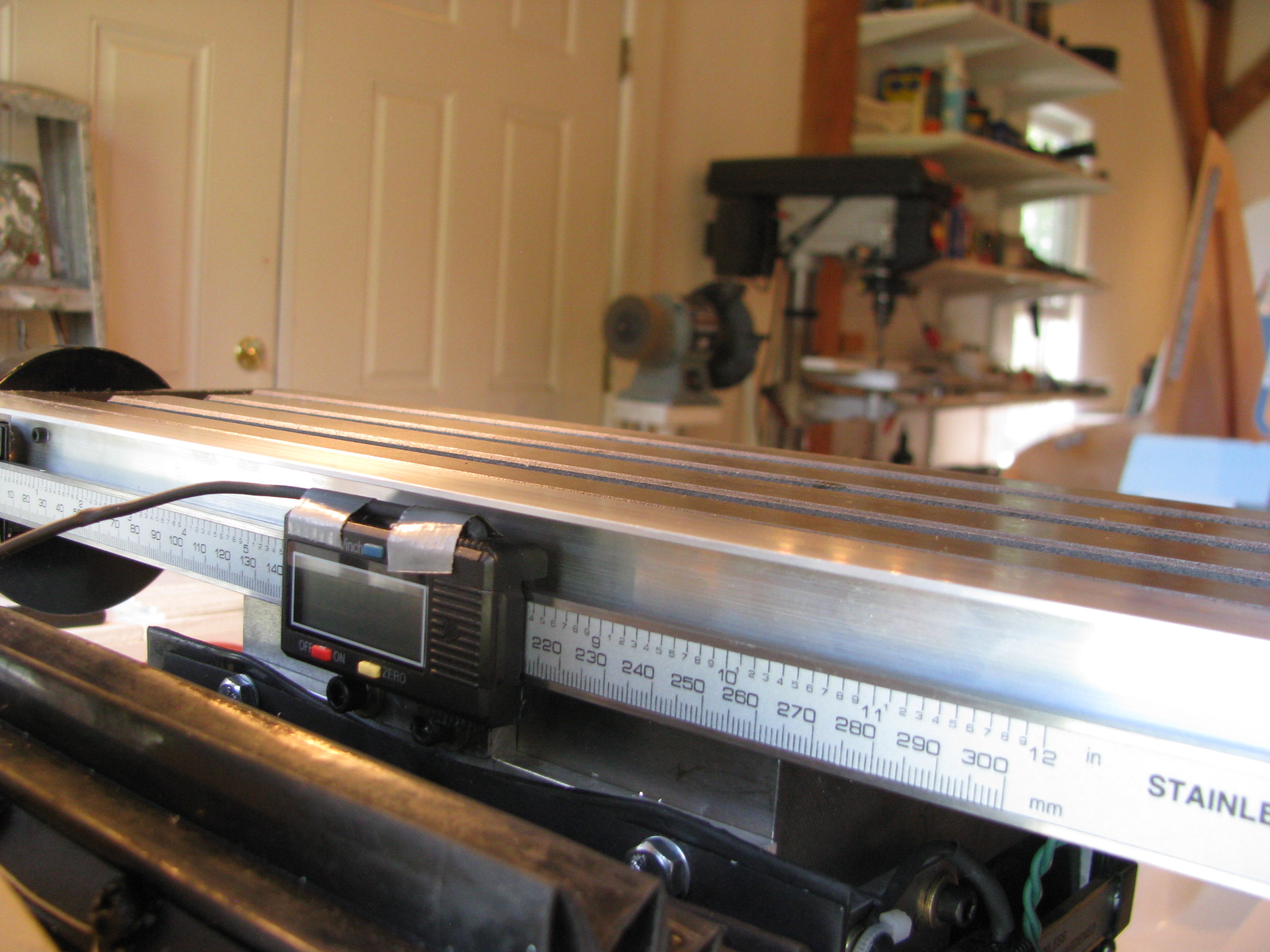
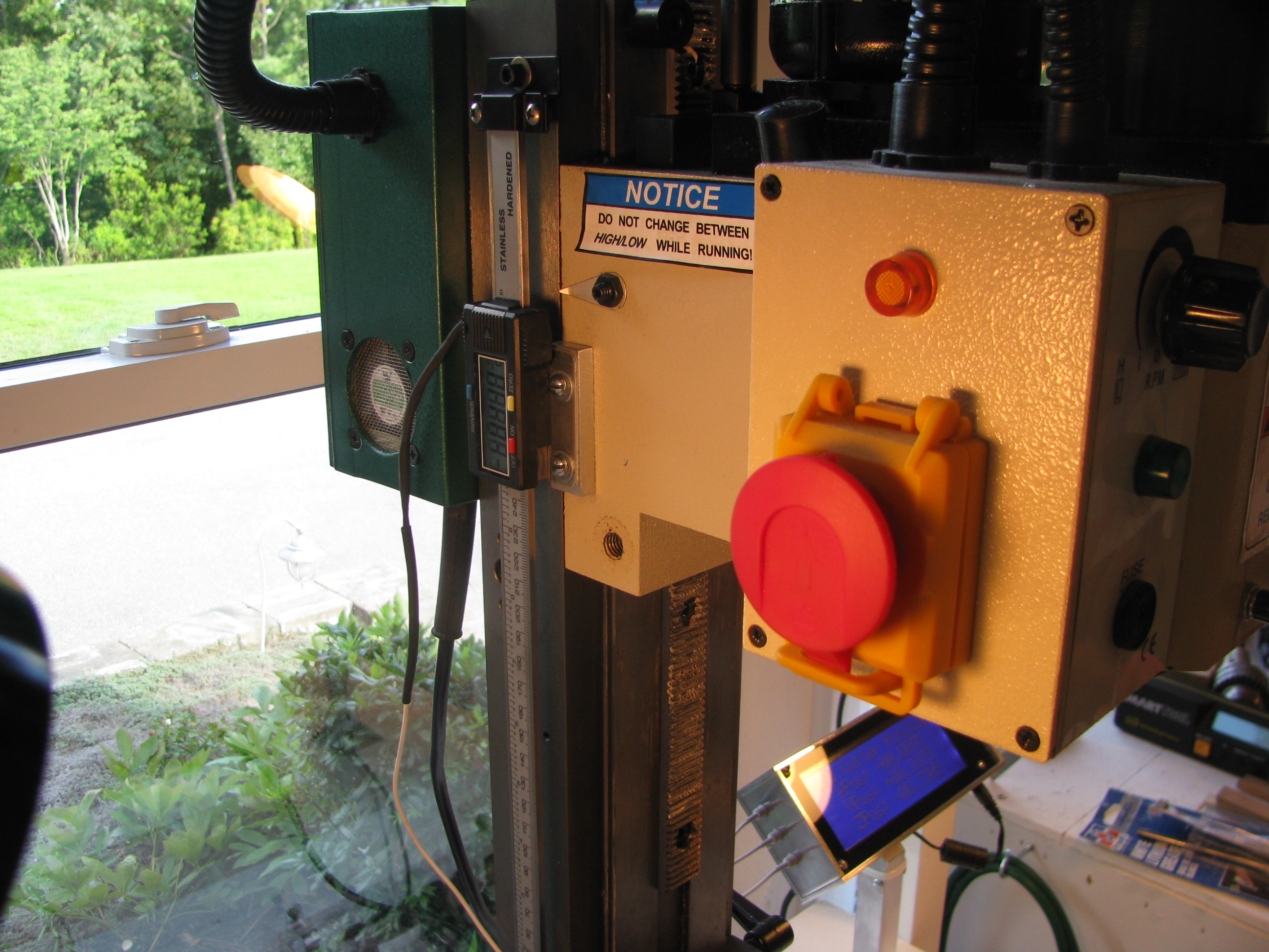
The crowning piece is a large-character 20x4 character LCD display also bought on eBay for $22.
I layed out a circuit and had it fabricated through Sunstone.com using their “Value Proto” service, which is relatively cheap. It’s mounted here behind the LCD. There are buttons on the right for zeroing out the reading on each axis independently for positioning on a workpiece.
The Arduino is clearly running at capacity to handle the three calipers worth of data. Each caliper has a clock and data line. The clock triggers an interrupt, which causes me to sample the data line on the respective port. Two of the clocks trigger the ATMega’s native pin interrupt functions and the third (Z-axis) triggers a pin change interrupt (which is a bit slower). About every 20 seconds or so one of the readings may glitch and a weird reading is indicated for one loop, probably because of a sampling error caused by the fact that the interrupts are happening right on top of each other, causing me to sample one reading incorrectly. It is so infrequent that it will not affect usage of the DRO.
Uber Weenie Alert!:
Here are the technical details of my DRO circuitry and Arduino code for my setup. If you have questions feel free to email me as the above descriptions are pretty terse:
DRO_SupportBD_sch.pdf
DRO_SupportBD_brd.pdf
DRO_Rev3.ino
LCD_Support.ino
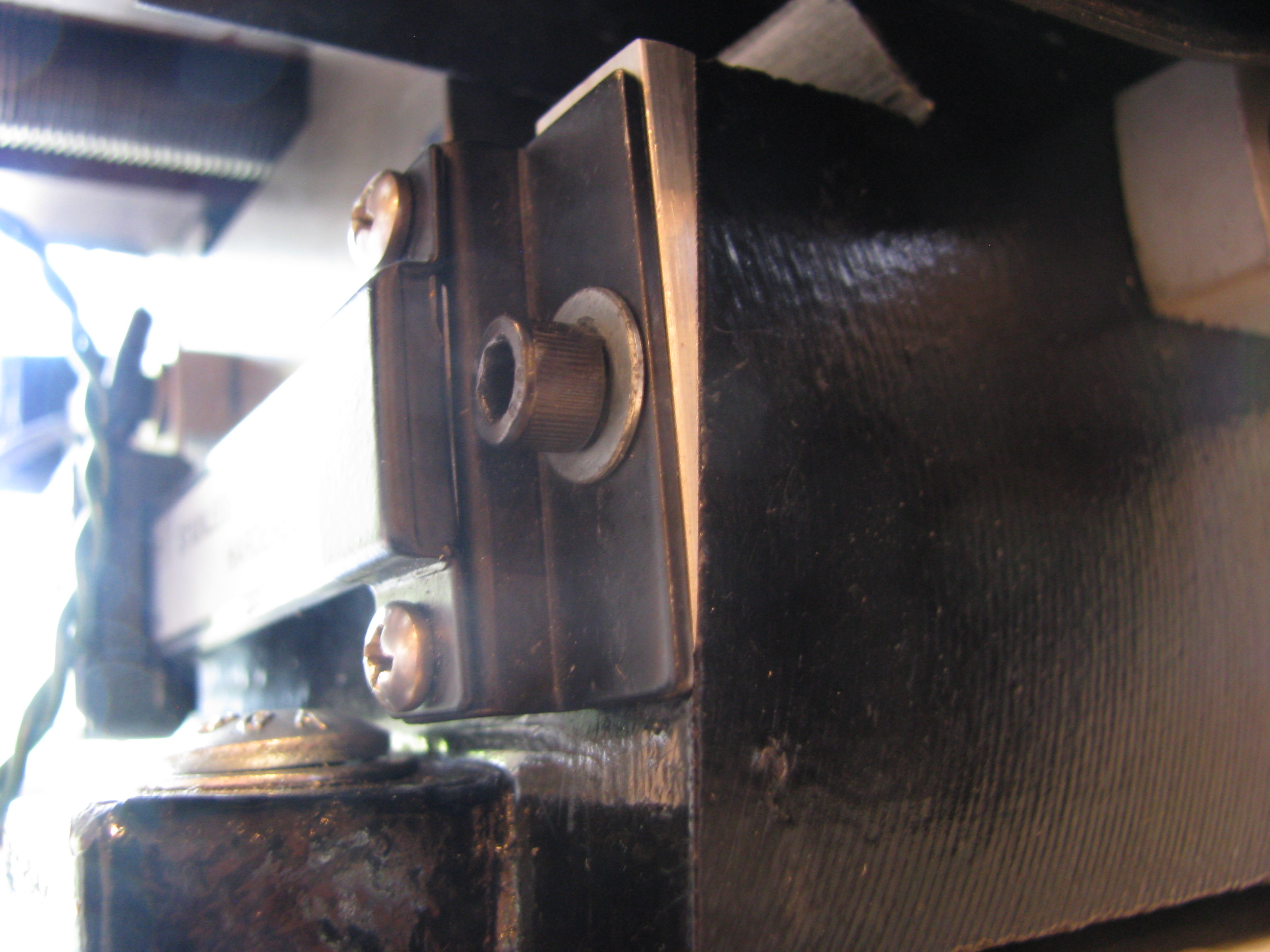
8/10/13 - DRO Mounting and Finishing of the Mill. I bought the FIgnoggle plans, and downloaded the free plans from the Little Machine Shop for mounting the DRO scales. Then I proceeded to ignore them both since they seemed overly complicated. They might make sense if you were trying to actually read the indicator on the scales themselves, but since I have my new big display, I found I could simplify the the mounting scheme to simple plates and spacers. The only tricky one was the 6degree wedge to vertically align the Y-axis mount with the base angle. No problem - I have a mill.
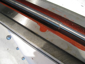
Y- Axis Mounting. The sliding part of the scale is mounted to the Y-axis carriage. An 0.040” plate is screwed into the caliper’s tapped holes, then 10-24 holes are drilled and tapped into the carriage (be careful - not to deep or you’ll hit the ways). There’s another 0.25” spacer behind those allen bolts, elevating the slider. The scale is fixed to the base using the supplied brackets and a wedge machined down from 0.25” plate. Just put an elongated slot in the wedge and you can slide it up or down until it is spaced properly.
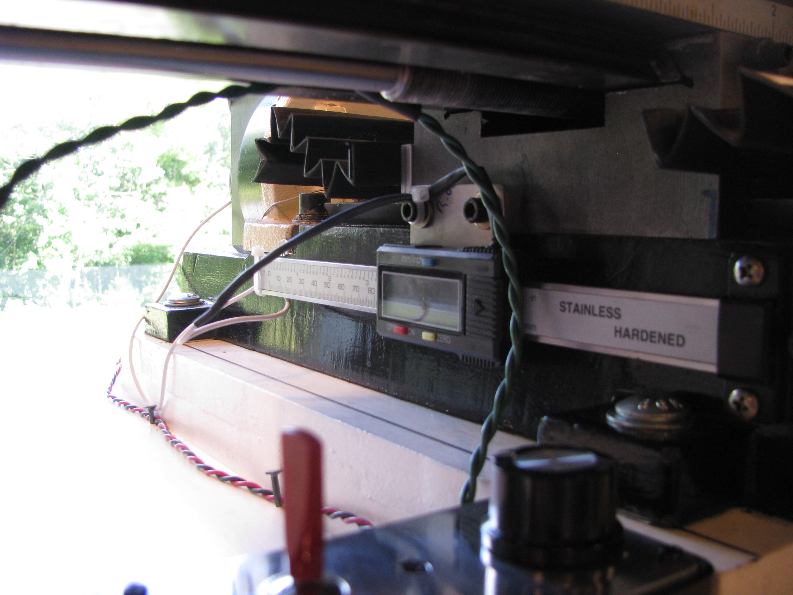
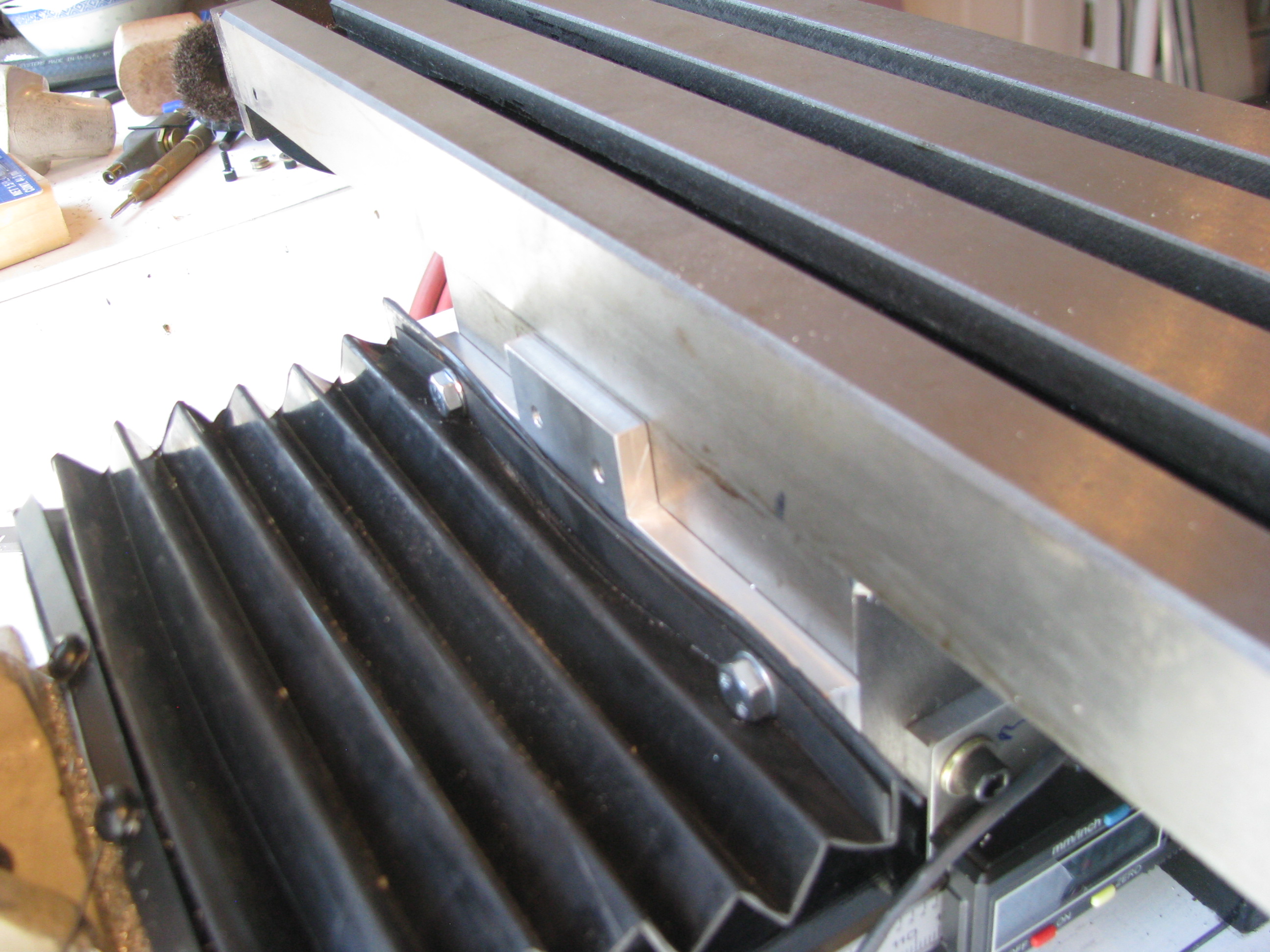
X-Axis mounting. I didn’t want the scale on the front since it would interfere with the Y-handle and the gib lock. The only tricky part was that there was no way I could drill from the back and I didn’t want to remove the column. I used the pre-existing holes for the rubber boot and machined a plate to mate with those pre-existing holes and allow for the slider plate no the caliper to screw into it. The scale is simply mounted to the table on one end. Only one hole is needed and washers (which I have many of and various thicknesses) to fix the scale to the table. The display is fixed to the Y-axis carriage, the scale is mounted ot the X-table. I then mounted a fixed angle to the table to cover and shield the scale.
Z-Axis DRO Mount - I removed the existing visual scale (next to useless), as well as the existing spring support. This freed up a lot of room to mount the DRO scale.I just opened up and tapped on of the already existing holes on the column, and drilled two holes in the head casting for the slider. Again, an 0.040” plate on the caliper slider and a 0.25” spacer on the head casting. Simple. As before, be careful not to drill&tap too deep on the casting or you’ll hit the ways.
Other Mods - I purchased the Air Spring kit from Little Machine Shop. This provides two things; 1) A better spring, which is more linear and allows for greater travel of the head, and 2) a longer rack so that you can lower the head much closer to the table.
DONE DONE DONE! Now, a fully enhanced X2 class mini-mill. Extended travels on X, Y, and Z axes, a power feed, and DRO on all three axes. Nice to be completed and I learned a lot and practiced more machining technique.
Took the opportunity to scrub the shop from top to bottom and prep for the next project(s) now that this one is in the bag.
Mill Power Feed
For airplane parts it is common practice to drill parts in assembly. In this case however, I made sketches and machined all the parts to spec, being careful on all the measurements. Even though not necessary, I was able to hold tolerances to +/- 0.001” on all dimensions. Not bad for a noob. Everything fit together with very tight tolerance and no play anywhere. Satisfying.
To link the drill shaft to the X-axis lead screw, I machined a coupler with a tongue that mates to a slot already present in the lead screw, and then drilled a hole through the coupler and drill shaft.
The coupler is threaded for a couple of 4-40 allen screws. When they are backed out the coupler spins freely on the drill shaft in case I want to machine without the power feed engaged. A little cumbersome and it it becomes a pain I will fit a quick-release pin instead of the screws.
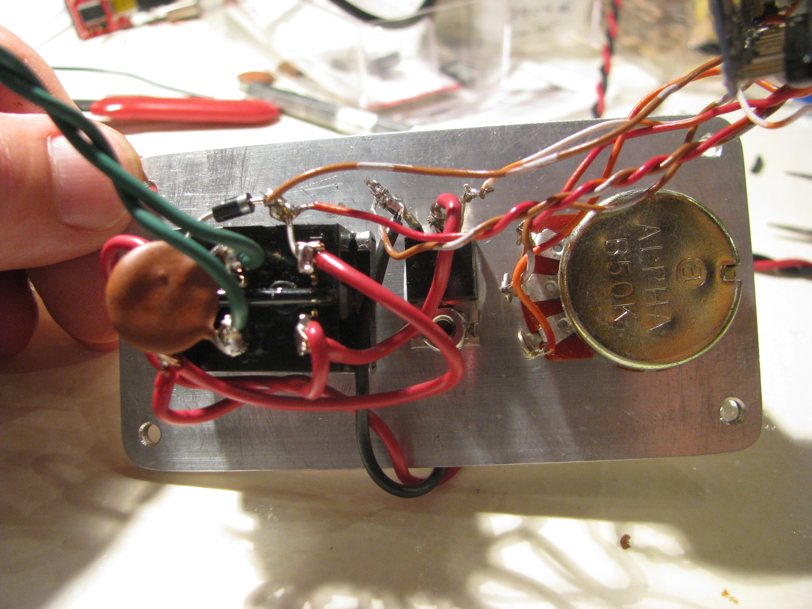
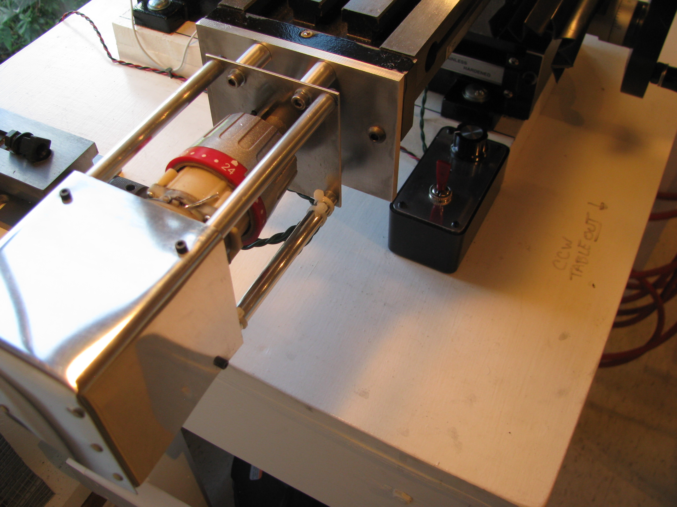
Speed Control for Power Feed. Being hooked up on the Arduino, I whipped up a little PWM program. It reads the voltage on a linear pot and adjusts a PWM signal output width. I just used a DPDT-Center Off switch to change direction and turn it off, so the Arduino’s job is simple. Just read a POT, adjust the PWM pulse width and drive a power FET (IRFZ44). A little Radio Shack Project box with the aluminum cover replaced with a 0.125” plate machined to accept the switch, POT, doubles as the heat sink for the FET as well. Works great.
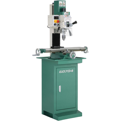
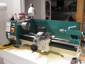
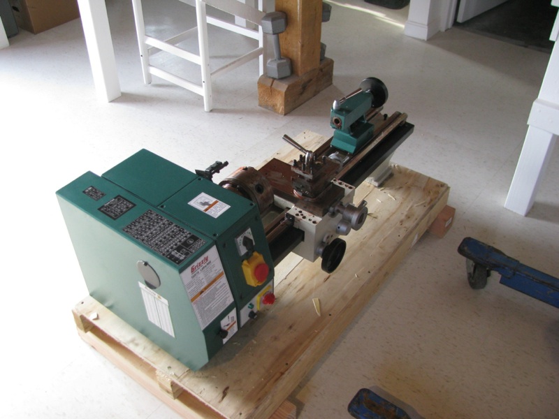
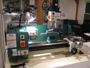
Milling Machine

About 3 years ago I invested in a Grizzly G0516 Lathe/Mill/Drill. The lathe is great. Very capable. The drill very precise. With patience you can drill very accurate holes. Milling left a lot to be desired. It took a lot of setup and then the machining was tough with the small mill table and relatively imprecise control using the lathe slide as the table movement control.
On paper it sounds great, but like many before, I have realized its limitations and really only used it for milling maybe 4 or 5 times seriously.
Little Machine Shop (.com) offers this milling table (shown here upside down). It is a little larger than a Sieg X2 table and the G0516 milling head bolts right to the back, effectively making a big-table X2 mill.
Step one is to fabricate a sturdy table made to fit in the only convenient spot left in my shop (too many projects). 4x4 legs, 2x6 table stringers, 3/4” ply and 3/4” mdf forming the top with 3 or 4 coats of urethane to seal it all up.
Everything is screwed and glued to keep it as stiff as possible. The surface is true within 0.1degree (I love my digital level).
As with the lathe, the first step is to take everything apart, clean off the shipping grease, and check all the surfaces. It felt pretty bad right out of the box - very sloppy movement - alternatively too tight and too loose with lots of side play.
That shipping grease turns to something like chewing gum and some of the sliding surfaces had paint on them. Don’t even think of using these Chinese machines right out of the box.
But as with the Grizzly, after a little work the motion cleans up, smooths out, and the tolerances can be snugged up substantially.
Virtually no play on the table movement once the gibs are adjusted. The motion is kind of stiff. After some use I may lap the ways and gibs to smooth it out and allow freer motion.
Complain as folks might about the Chinese machine tools, the value per dollar is amazing.
I don’t have any pictures of my tramming - my first time doing it with any precision. It took hours. I first made a tool I could chuck up in the mill that rigidly held my dial indicator 3-4 inches off centerline.
The Y error was about 9 mils at the start. This is the fore/aft “lean” of the mill column. To adjust it you unbolt the casting that holds the giant column mount stud, tilt it the appropriate direction and add shims to the appropriate side. Very thin shims. Doing the trig showed that I needed 2.5-3.5 mils of shim. My thinnest shim stock is 5 mill brass, so I ended up using aluminum foil. Lightly grease up one side (so it sticks) and layer it together. I needed a strip about 3 layers thick to get the Y tram. Since aluminum is not the strongest, I will have to check this periodically.
Since the column is designed to tilt left and right, it is just a matter of loosening the giant bolt and tilting/bumping the head until things are accurate, then snugging it down.
I ended up with about 0.5 mil Y tram error and just less in the X. I only have a dial indicator, so this is all probably within the error of the indicator, but sufficient for anything i will need it for.
Interestingly, the Jacob’s chuck had about 1.5mills of runout (since I was measuring stuff anyway). When I switch to a milling collet I will check the runout of that to see if its the chuck or the spindle head (I hope it’s the chuck).
The lathe denuded of the milling head. Whenever I needed the lathe it seemed I had t set up to drill and vice versa. This new arrangement should be much more efficient and I will be more inclined to use the mill for precision drilling instead of the old drill press.
Next up is to add my DRO indicators to the mill table. I’m going to make some chips first.
Moving & Restarting
 It had to happen that as soon as I acquired the Helicycle and bought a lathe we ended up selling the old house. After 2 years on the market and a bunch of jerking around we finally accepted an offer (for a fraction of our original asking price, of course).
 One of the motivators in settling for a lower price is that we had found a new place on top of a hill, 360 views, and a large outbuilding which has turned into the new airplane factory.
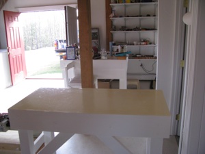
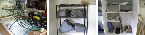
I started by gutting the outbuilding, tearing out the walls and retiling the floors. All the wiring had to be redone, drywalling, and finishing. White white white. It looks like an operating theater now.
I built worktables, installed shelving, and redid the lighting. Between the move, and the refitting of the shop, I did not get anything done on the aircraft until well into fall.
It looked huge right up until the airplane and helicopter fuselage and frame were brought in. Now it’s quite snug.
My personal vow is that we will NOT move again until the airplane and helicopter are finished. What a PITA to move that stuff.
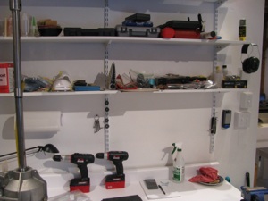
Lots of shelves and countertop space.
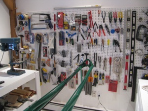
New pegboards gave a chance to reorganize the tools. It’s nice to have them all neat and logical again.
I was pretty lost for a couple of months during the move with everything in boxes. If I needed a wire stripper it was an hour-long treasure hunt through boxes.
Much, much happier now knowing where everything is.
Just prior to selling the house (and the REAL trigger for getting a good offer), was my taking receipt of a Grizzly G0516 Mill/Lathe. This is a couple of steps up from a little mini lathe.
Yes, yes, I’ve read all the reviews saying a 3-in-1 is not as good as separate machines, but I have limited space, and don’t see myself using it every day.
I have played around and made some small items so far. Fun. Looks like it will more than meet my limited needs.
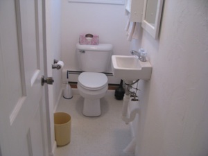
One of the more luxurious aspects of the new shop is having a bathroom and shower. A small electric water heater caps it.
Unfortunately the water run to the shop was buried less than 12 inches from the surface underground. The biggest single project I undertook was to dig up the old water run, and dig a new trench (by hand) 36-48 inches deep. 137 feet long. There were two spots where ledge prevented a deep lay. The pipes are about 8 inches deep at those points.
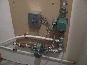
I ran a conduit with 2 x1”insulated PEX pipes. In the house there is a loop manifold.
In the shop I put two circulator pumps. One just loops water through the feed and return. The second circulator loops the feed through the hot water heater and back out the return.
I can program the timer to loop hot water 1 minute out of 10 or 1 minute out of 20, depending on how cold it is out.
If I get super motivated someday I will add a thermocouple to the return and optimize so I am not
paying as much to heat the ground.

One section of the shop is set up as an office/lounge with a desk, couch, comfy chair, laptop, internet and a TV.
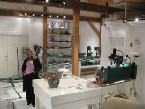
Comfy shop, beautiful wife. Should be a good place to work and play.
Project Start
Busy month. I finished refurbishing the garage, which is quite full at this point with the RV8A still in there, and all the fittings for the new project. I painted every surface white, and discovered something really cool. Periodically Lowe's has some killer deals on pre-fabricated bathroom cabinets. A couple of sections of those with a pre-fab countertop makes a nice workbench/storage cabinet. I am sure it is not precisely, perfectly flat, but pretty darned close. I will shim and do all critical tolerance work on my flush surface in the downstairs shop. The project is all here. I received the rotor blades from Eagle. The only thing left from them is the turbine itself, which I have no immediate need for anyway, so delivery, though promised "soon" is not super critical to me at this time.
Harbor Freight is my friend. I picked up a bunch of odds & ends I didn't already have; a 4" die grinder, more clamps, a 1" belt sander, blades, etc...
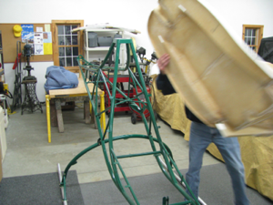
Real Project Work!! I first started by checking over all the Group 1 work done by the previous kit owner. He got as far as mounting the frame on the skids, then starting to clean up the seat pan. The gear mounting looks acceptable. His holes are square and I should just need to replace the hardware with known good and properly sized items at final assembly. Though his work seems acceptable, his color choices were not. Green?!? That'll change for sure. The seat cushions are also a hideous purple/pink combo which will probably end up getting replaced at some point.