
Mill DRO Design & Build
07/12/13 18:43 Filed in: All
Clearly an accurate digital readout of the X, Y and Z-positions of the table and mill head will make jobs go much faster.
I purchased 2x12” and 1x8” digital caliper mechanisms off eBay for $24 for the 12” and $18 for the 8” respectively. I have read about various folks interfacing to those and hooked the interface signals up to a scope and observed and played around until I figured out exactly the protocol coming over the interface ports from the calipers.
For the ones I purchased the protocol seems slightly different than that measured by others. In my case the value output over the interface is simply a hex representation of the position in whatever units are selected (mm or in). One of the bits indicates the sign (it is not true twos complement), and another bit indicates the 0.0005” indication.
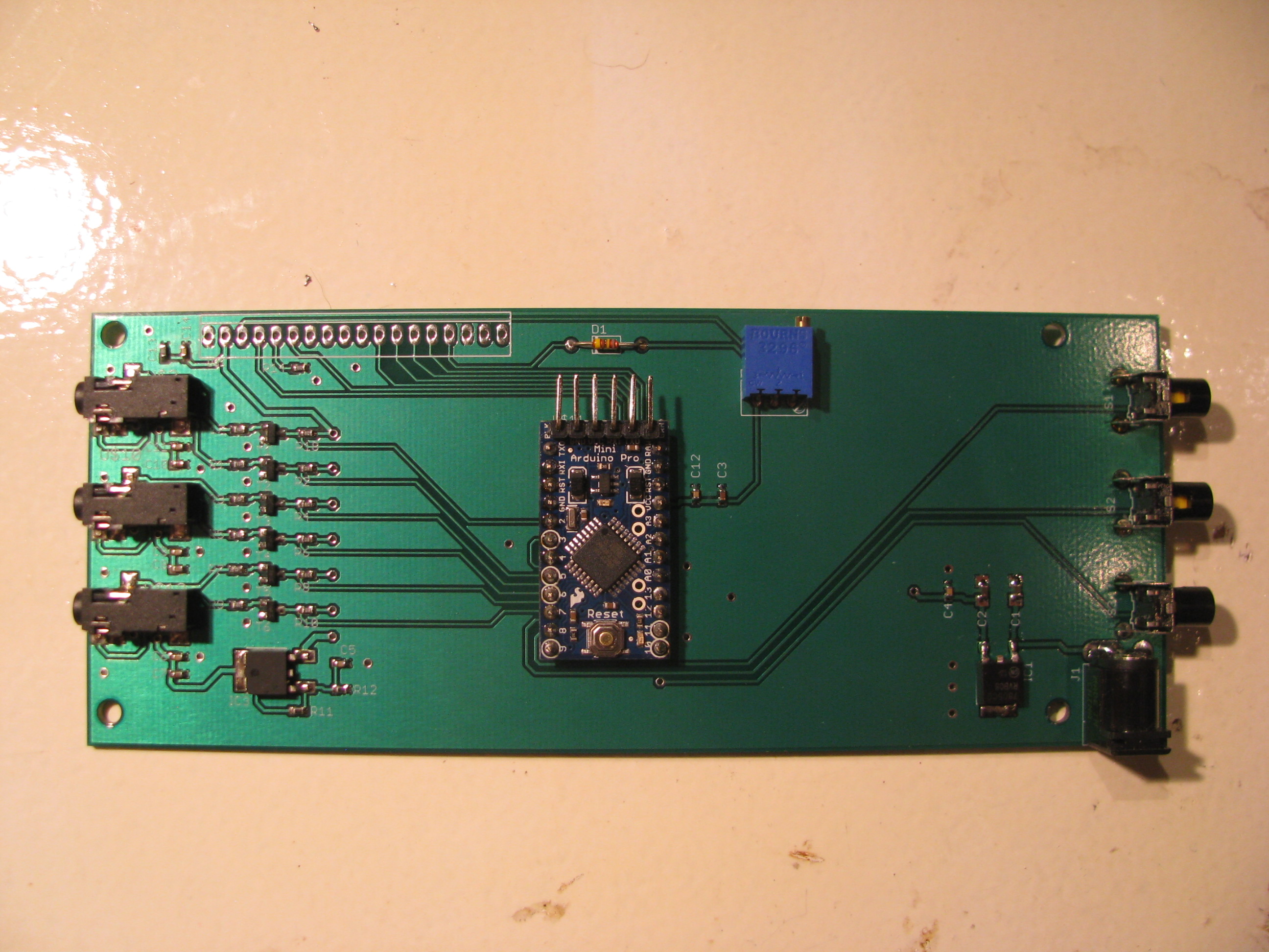
I whipped up a circuit to convert the voltage levels and wrote code to read the three values with an Arduino (that’s a ProMini in the center). I soldered the wires from 3 cellphone headsets (4-pin 3.5mm plugs with very, very fine flexible wires) to the caliper ports. The complete headsets were $0.99 each on eBay, which is cheaper than it would have been to buy connectors and cable and make my own. There’s $7 of buttons, connectors, passives, transistors, and regulators from Digikey rounding out the B.O.M.
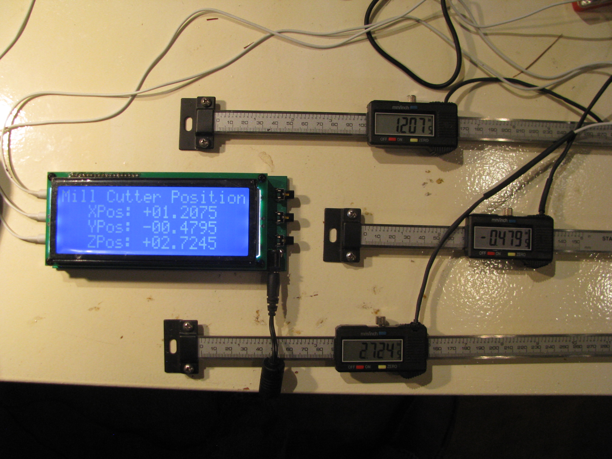
The crowning piece is a large-character 20x4 character LCD display also bought on eBay for $22.
I layed out a circuit and had it fabricated through Sunstone.com using their “Value Proto” service, which is relatively cheap. It’s mounted here behind the LCD. There are buttons on the right for zeroing out the reading on each axis independently for positioning on a workpiece.
The Arduino is clearly running at capacity to handle the three calipers worth of data. Each caliper has a clock and data line. The clock triggers an interrupt, which causes me to sample the data line on the respective port. Two of the clocks trigger the ATMega’s native pin interrupt functions and the third (Z-axis) triggers a pin change interrupt (which is a bit slower). About every 20 seconds or so one of the readings may glitch and a weird reading is indicated for one loop, probably because of a sampling error caused by the fact that the interrupts are happening right on top of each other, causing me to sample one reading incorrectly. It is so infrequent that it will not affect usage of the DRO.
Uber Weenie Alert!:
Here are the technical details of my DRO circuitry and Arduino code for my setup. If you have questions feel free to email me as the above descriptions are pretty terse:
DRO_SupportBD_sch.pdf
DRO_SupportBD_brd.pdf
DRO_Rev3.ino
LCD_Support.ino
8/10/13 - DRO Mounting and Finishing of the Mill. I bought the FIgnoggle plans, and downloaded the free plans from the Little Machine Shop for mounting the DRO scales. Then I proceeded to ignore them both since they seemed overly complicated. They might make sense if you were trying to actually read the indicator on the scales themselves, but since I have my new big display, I found I could simplify the the mounting scheme to simple plates and spacers. The only tricky one was the 6degree wedge to vertically align the Y-axis mount with the base angle. No problem - I have a mill.
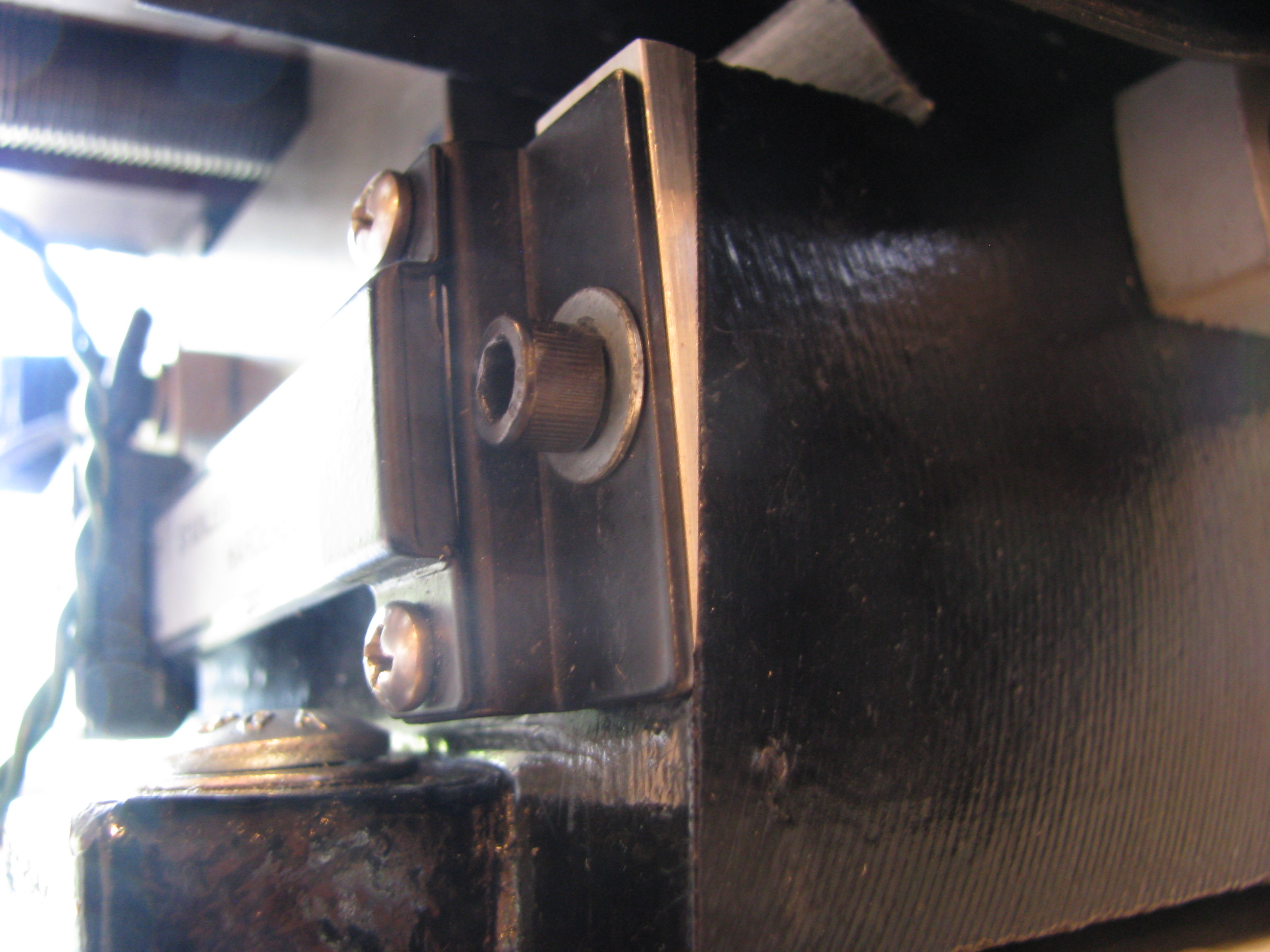
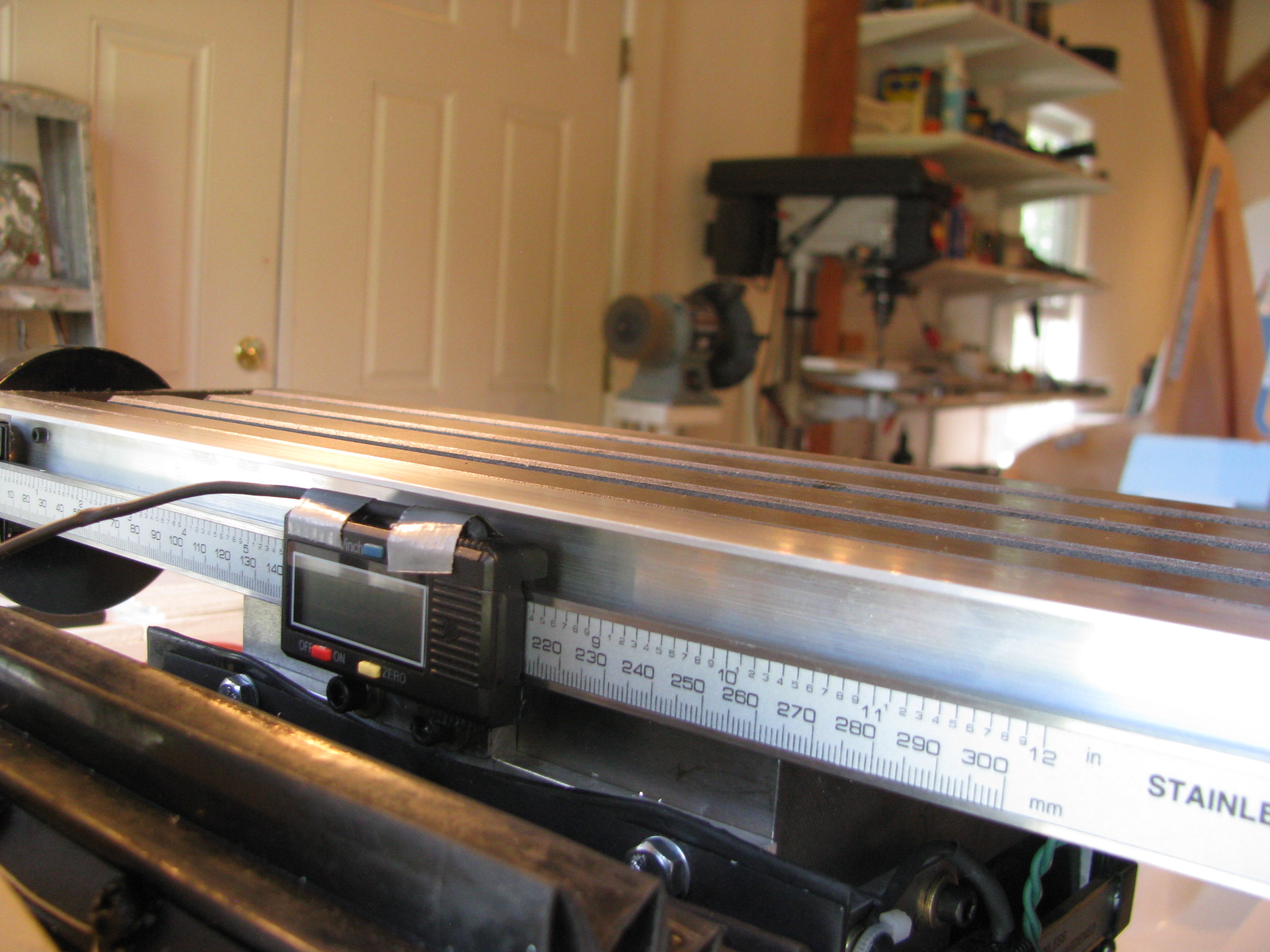
Y- Axis Mounting. The sliding part of the scale is mounted to the Y-axis carriage. An 0.040” plate is screwed into the caliper’s tapped holes, then 10-24 holes are drilled and tapped into the carriage (be careful - not to deep or you’ll hit the ways). There’s another 0.25” spacer behind those allen bolts, elevating the slider. The scale is fixed to the base using the supplied brackets and a wedge machined down from 0.25” plate. Just put an elongated slot in the wedge and you can slide it up or down until it is spaced properly.
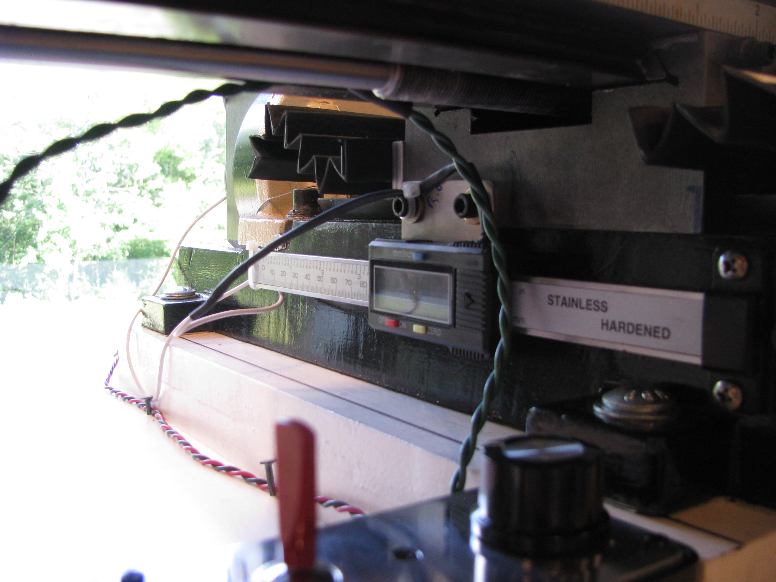
X-Axis mounting. I didn’t want the scale on the front since it would interfere with the Y-handle and the gib lock. The only tricky part was that there was no way I could drill from the back and I didn’t want to remove the column. I used the pre-existing holes for the rubber boot and machined a plate to mate with those pre-existing holes and allow for the slider plate no the caliper to screw into it. The scale is simply mounted to the table on one end. Only one hole is needed and washers (which I have many of and various thicknesses) to fix the scale to the table. The display is fixed to the Y-axis carriage, the scale is mounted ot the X-table. I then mounted a fixed angle to the table to cover and shield the scale.
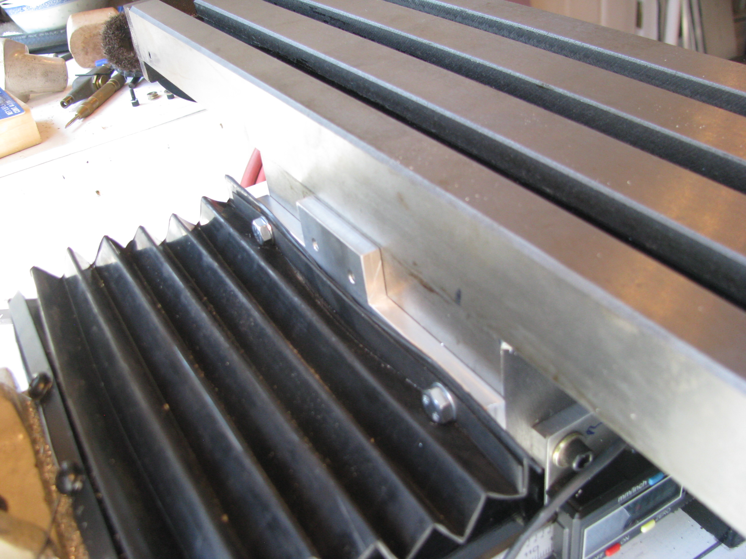
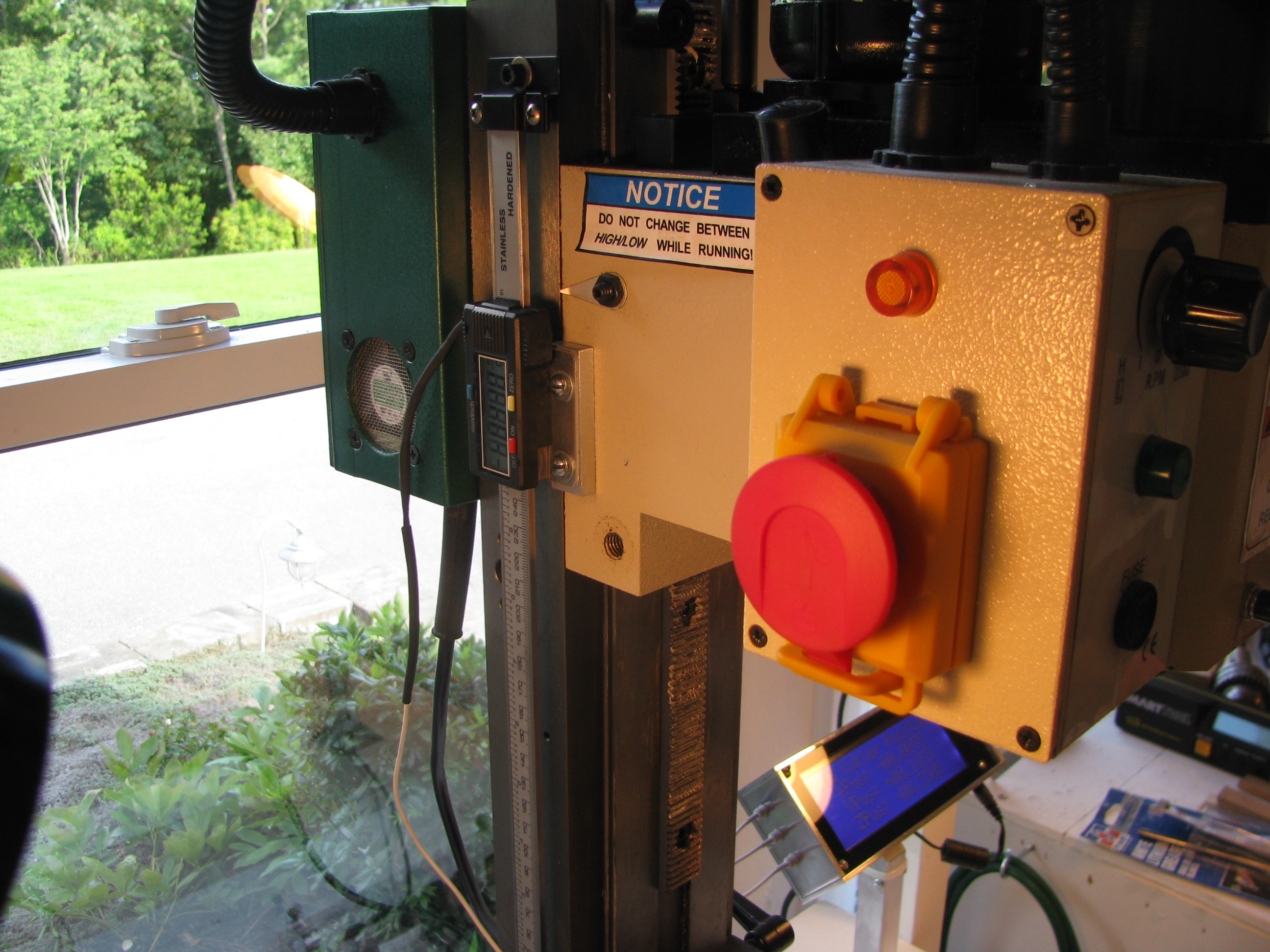
Z-Axis DRO Mount - I removed the existing visual scale (next to useless), as well as the existing spring support. This freed up a lot of room to mount the DRO scale.I just opened up and tapped on of the already existing holes on the column, and drilled two holes in the head casting for the slider. Again, an 0.040” plate on the caliper slider and a 0.25” spacer on the head casting. Simple. As before, be careful not to drill&tap too deep on the casting or you’ll hit the ways.
Other Mods - I purchased the Air Spring kit from Little Machine Shop. This provides two things; 1) A better spring, which is more linear and allows for greater travel of the head, and 2) a longer rack so that you can lower the head much closer to the table.
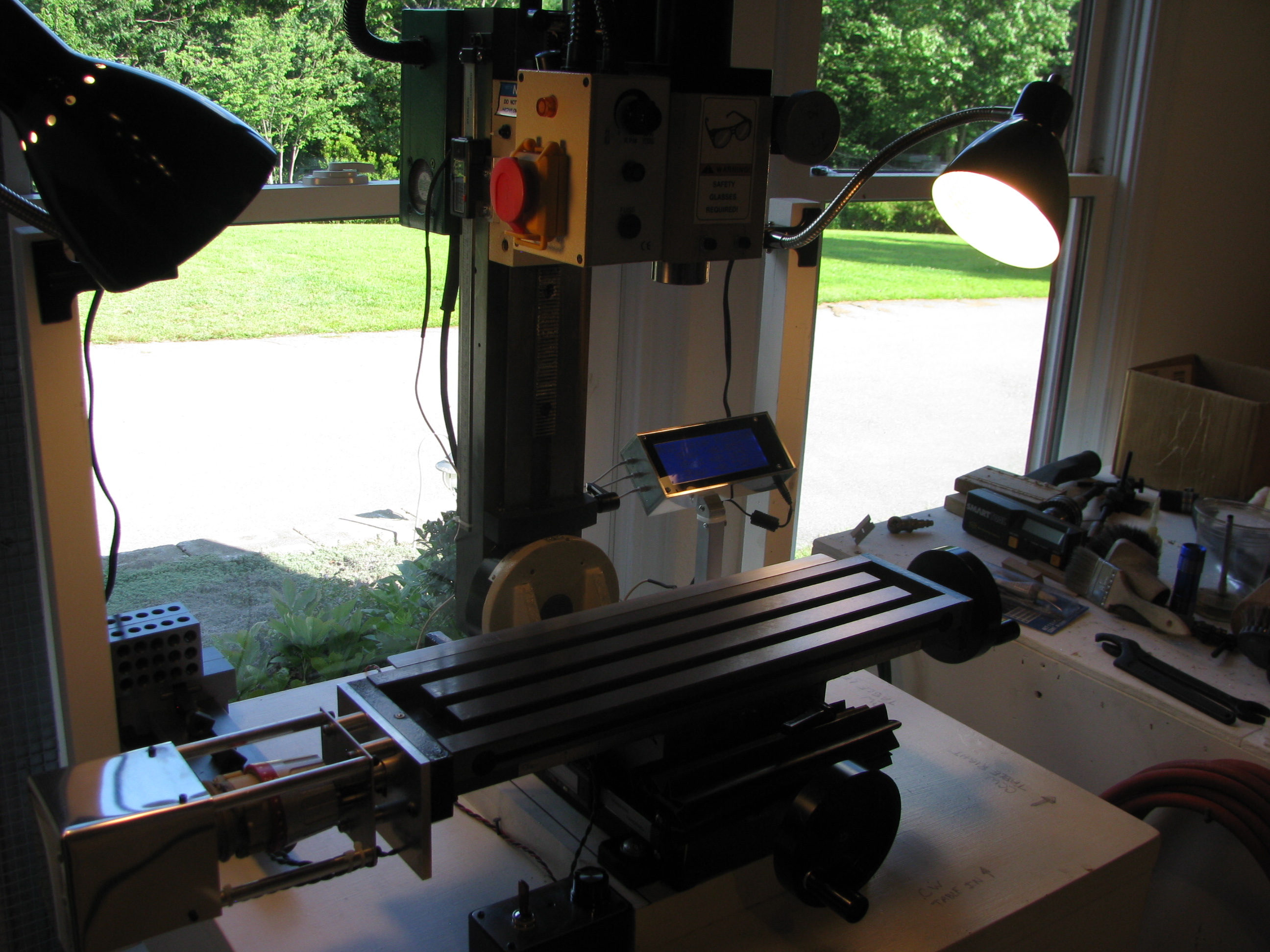
DONE DONE DONE! Now, a fully enhanced X2 class mini-mill. Extended travels on X, Y, and Z axes, a power feed, and DRO on all three axes. Nice to be completed and I learned a lot and practiced more machining technique.
Took the opportunity to scrub the shop from top to bottom and prep for the next project(s) now that this one is in the bag.