
Mounting TR Assy
03/24/12 13:35 Filed in: All
The actual kit I have (build 5) differs a little from what you see in the videos. I am assuming things have improved and the differences are due to improvements over time. One area is the tail rotor attachment. BJ makes reference to prick punch marks and precision fitment. In my case the yoke is drilled on one side only and is quite a bit undersize for an AN4 Bolt.
There are no matching prick punch marks.
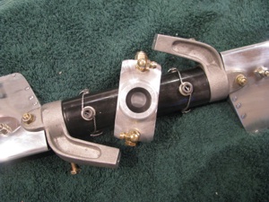
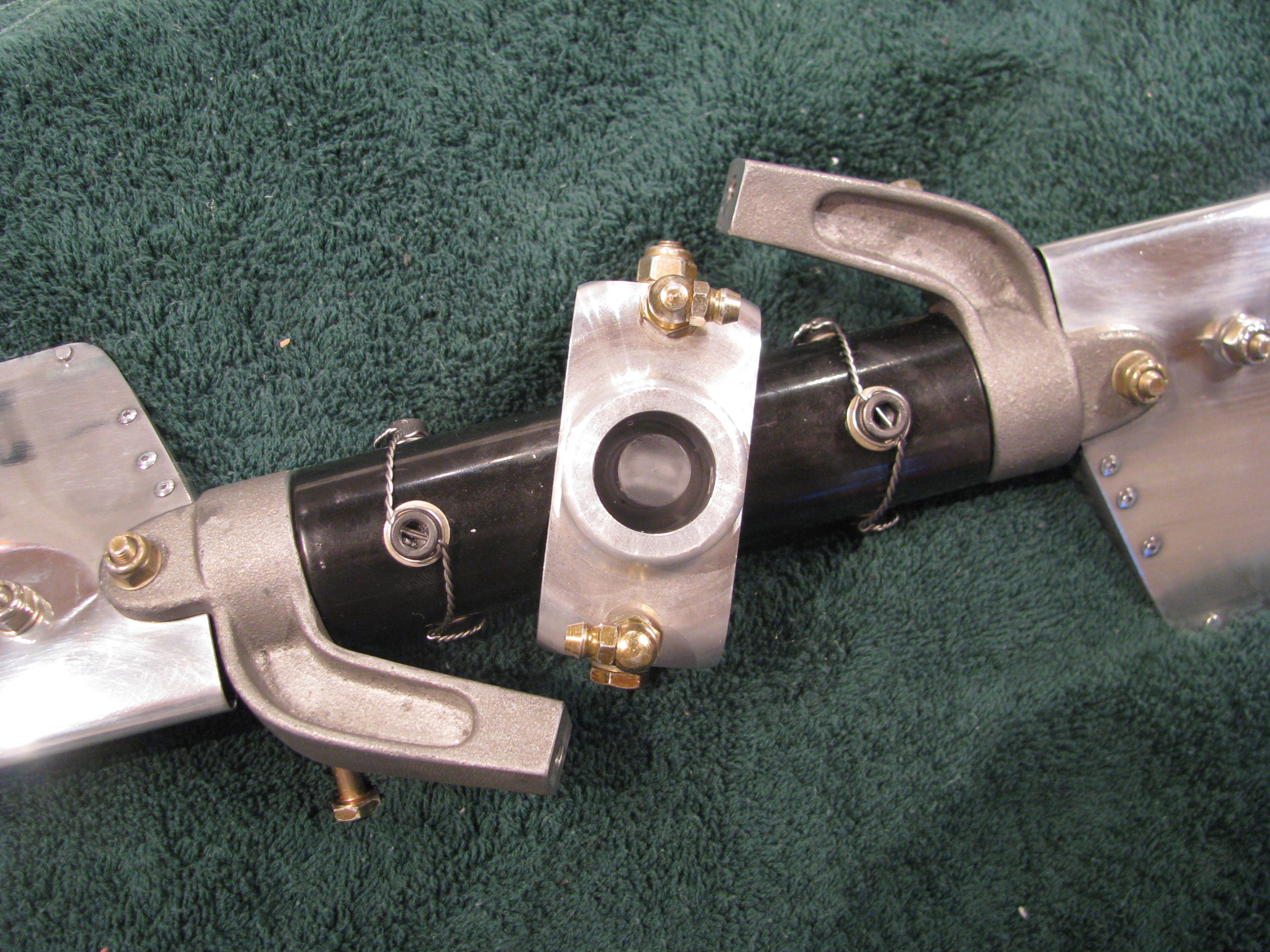
Here is the business end of the tail rotor hub looking into the yoke. The plastic piece in the center is the “flapping restraint” plug. The allen bolts have been drilled and safety wired.
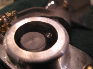
Looking into the yoke you can see the undrilled side. I searched the builders group and contacted Keith Southard whose kit was of the same vintage. He had the same situation and recommended a procedure for finish drilling this hole precisely with no slop.
The builder’s site is a great resource. Collectively there is a ton of information assembled and very knowledgable folks who are pretty responsive are active on it.
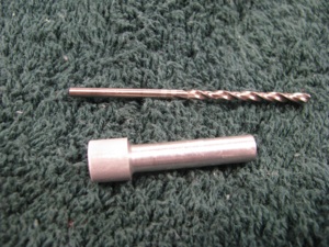
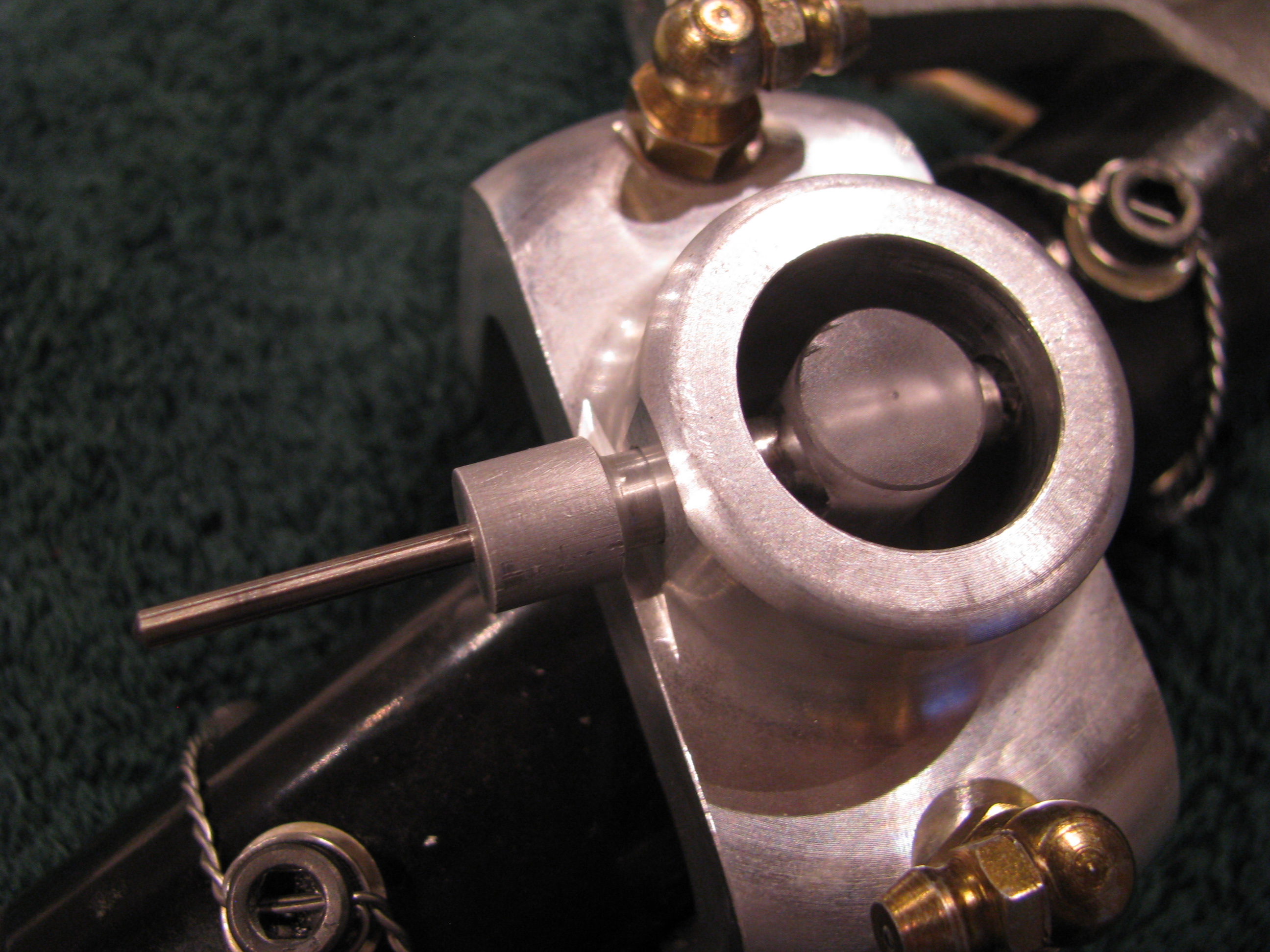
Start by making a drill bushing so a pilot can be drilled on the unfinished yoke side that will be perfectly centered. I chucked up an aluminum rod and lathed it down until it just barely and snugly fit in the hole on the drilled side. Then center bore a hole in the bushing for the pilot drill.
True to form, I messed up the first one, so I gave it a gentle chamfer and will use it as a drift to get everything lined up before employing the bushing and drilling for real.
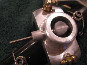
The idea is that I will drill the far side yoke hole with the drill bushing in assembly and then open it up slowly.
The final couple of steps, including the reaming, if necessary, will be done in assembly so there is absolutely no slop. I will procure a collection of the correct length AN4 bolts including some “close fit” bolts so I have a selection to choose from . It is surprising how different bolts in the same bag can have different diameters by +/- a couple of a mils.
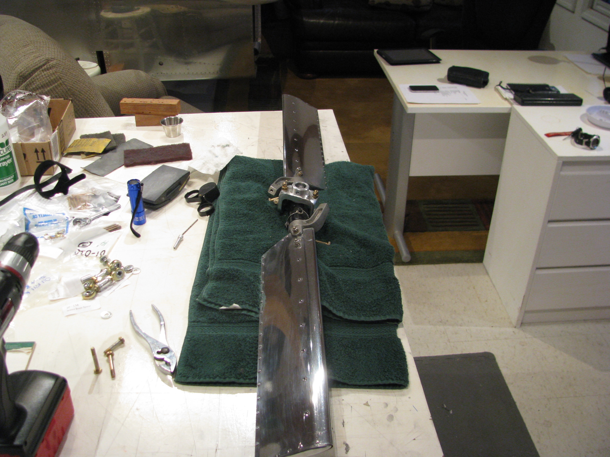
I also purchased kit of Nuvite Aluminum polish after reading Juan Rivera’s site and seeing his results. My plan is to polish the TR (no paint) as well as the TR drive shaft, main blades, and perhaps skids.
Now I am no expert. I just got the stuff. There are several different grades from the coarsest to the finest.
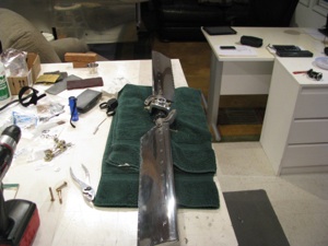
It doesn’t take a lot of brainpower, but it does take a lot of patience to get results. This is my first pass on the TR blades. It already looks better than anything I’ve ever polished before and I am sure I will repeat the sequence after all the handling of the TR is complete - so it will only get better.

Now I don’t think I’ll ever be as patient as Juan in getting the finish he shows on his web site, but it’ll still look good.
Polishing seems to have this bi-modal perception. You can get it looking shiny and very good. Stopping there would be fine. THEN , you decide to get mirror-like results and it’ll look like crap because once part of the surface shines up like a mirror, all the minor scratches and striations in the other areas become evident until the entire surface is perfect.
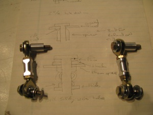
TR pitch link hardware. I blindly followed BJs instructions and cut 11/16 off the threads on the rod ends. You could probably leave another 1/16th or two on the ends (more threads to engage) as there is no way they will interfere with each other when screwed all the way in to the aluminum couplers.
I find that I am often making little sketches as I watch the videos (over and over) to have something to refer to in the shop.
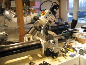
Drilling the safety wire holes in the slider would be a bit of a challenge without the mill. This is the first time I have ever angled the head over. The bearing block is then clamped to the surface in such a way that there is no side load on the bearing itself through the use of 3 large fender washers underneath the inner race.
As in most machining operations, the machine setup and work holding take 90% of the time. The actual metal cutting is but a few seconds.

The outer race is supported underneath with some blocks so there is no side load on the bearing. A center drill is absolutely necessary for its stiffness. Drill just deep enough so that a normal bit will not jump out.
The first hole was a mess, the second better, and by the fourth it was perfect. I’m sure my second helicopter would be absolute perfection.
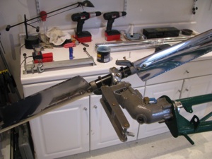
TR pre-assembled. Couldn’t resist spinning it around.
When I did this, however, I noticed that the slider bearing was not spinning cleanly. The bearing is defective and “ticks” as it spins. You can feel the “hitches” when you spin it by hand on the bench. I called Blake and he agreed that it didn’t sound right. It’s on its way back to Eagle to have a new one pressed in.
There are no matching prick punch marks.
Here is the business end of the tail rotor hub looking into the yoke. The plastic piece in the center is the “flapping restraint” plug. The allen bolts have been drilled and safety wired.

Looking into the yoke you can see the undrilled side. I searched the builders group and contacted Keith Southard whose kit was of the same vintage. He had the same situation and recommended a procedure for finish drilling this hole precisely with no slop.
The builder’s site is a great resource. Collectively there is a ton of information assembled and very knowledgable folks who are pretty responsive are active on it.

Start by making a drill bushing so a pilot can be drilled on the unfinished yoke side that will be perfectly centered. I chucked up an aluminum rod and lathed it down until it just barely and snugly fit in the hole on the drilled side. Then center bore a hole in the bushing for the pilot drill.
True to form, I messed up the first one, so I gave it a gentle chamfer and will use it as a drift to get everything lined up before employing the bushing and drilling for real.
The idea is that I will drill the far side yoke hole with the drill bushing in assembly and then open it up slowly.
The final couple of steps, including the reaming, if necessary, will be done in assembly so there is absolutely no slop. I will procure a collection of the correct length AN4 bolts including some “close fit” bolts so I have a selection to choose from . It is surprising how different bolts in the same bag can have different diameters by +/- a couple of a mils.
I also purchased kit of Nuvite Aluminum polish after reading Juan Rivera’s site and seeing his results. My plan is to polish the TR (no paint) as well as the TR drive shaft, main blades, and perhaps skids.
Now I am no expert. I just got the stuff. There are several different grades from the coarsest to the finest.
It doesn’t take a lot of brainpower, but it does take a lot of patience to get results. This is my first pass on the TR blades. It already looks better than anything I’ve ever polished before and I am sure I will repeat the sequence after all the handling of the TR is complete - so it will only get better.
Now I don’t think I’ll ever be as patient as Juan in getting the finish he shows on his web site, but it’ll still look good.
Polishing seems to have this bi-modal perception. You can get it looking shiny and very good. Stopping there would be fine. THEN , you decide to get mirror-like results and it’ll look like crap because once part of the surface shines up like a mirror, all the minor scratches and striations in the other areas become evident until the entire surface is perfect.
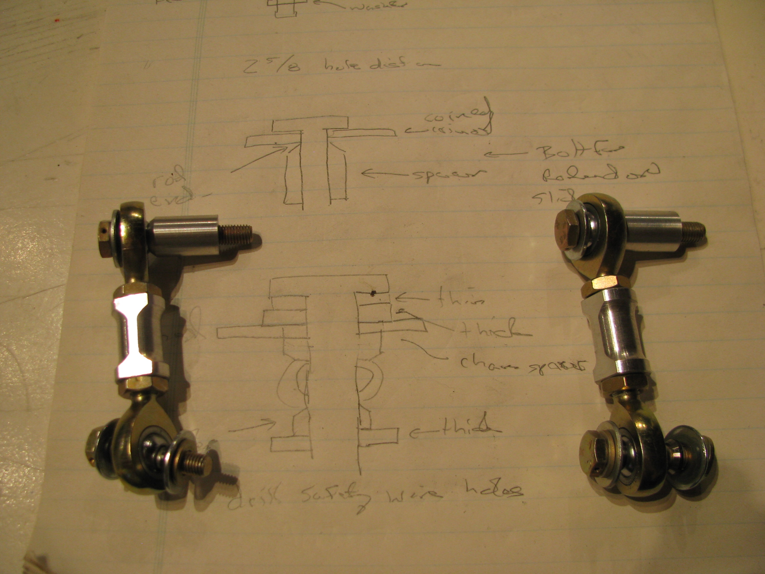
TR pitch link hardware. I blindly followed BJs instructions and cut 11/16 off the threads on the rod ends. You could probably leave another 1/16th or two on the ends (more threads to engage) as there is no way they will interfere with each other when screwed all the way in to the aluminum couplers.
I find that I am often making little sketches as I watch the videos (over and over) to have something to refer to in the shop.
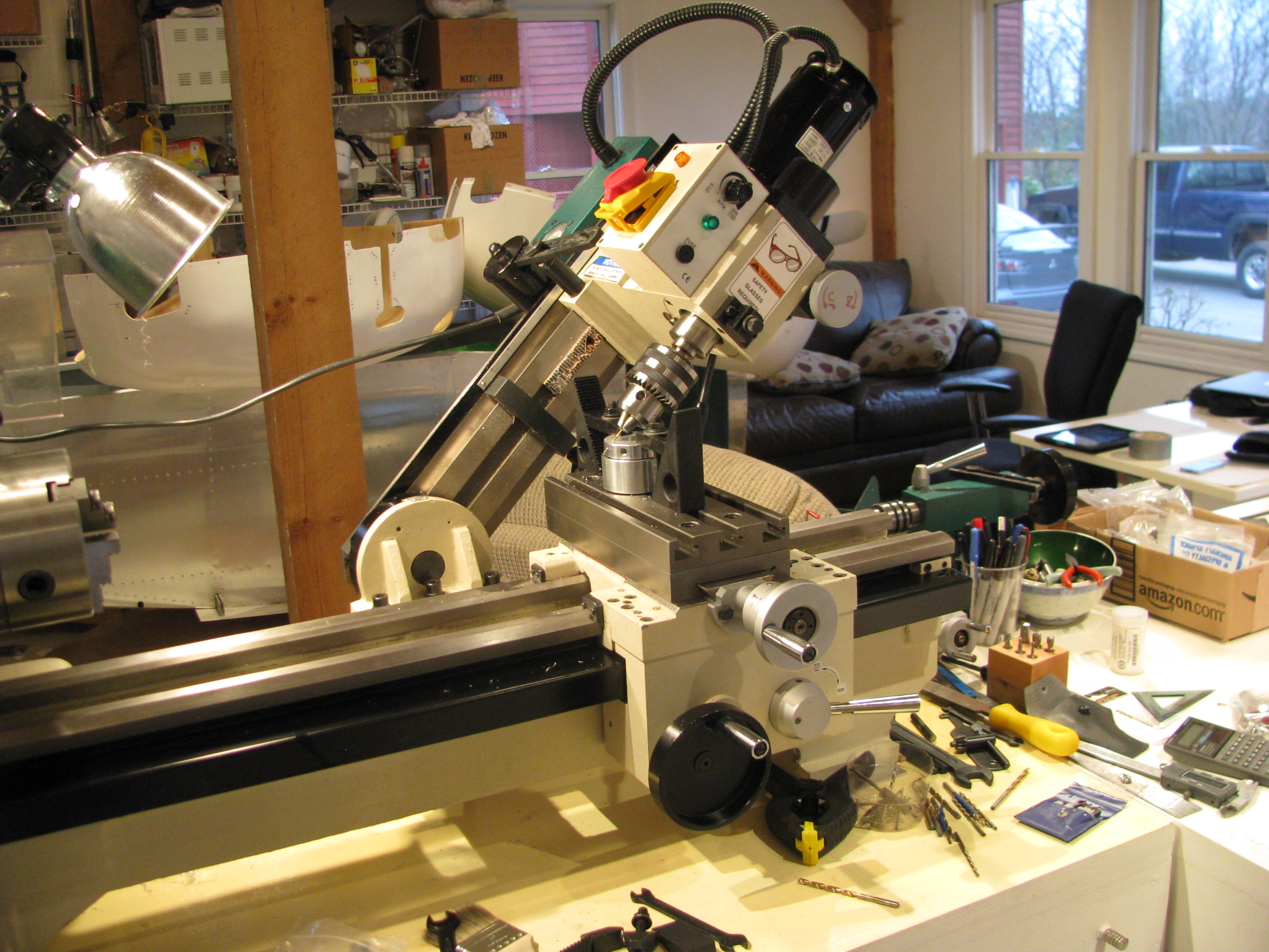
Drilling the safety wire holes in the slider would be a bit of a challenge without the mill. This is the first time I have ever angled the head over. The bearing block is then clamped to the surface in such a way that there is no side load on the bearing itself through the use of 3 large fender washers underneath the inner race.
As in most machining operations, the machine setup and work holding take 90% of the time. The actual metal cutting is but a few seconds.
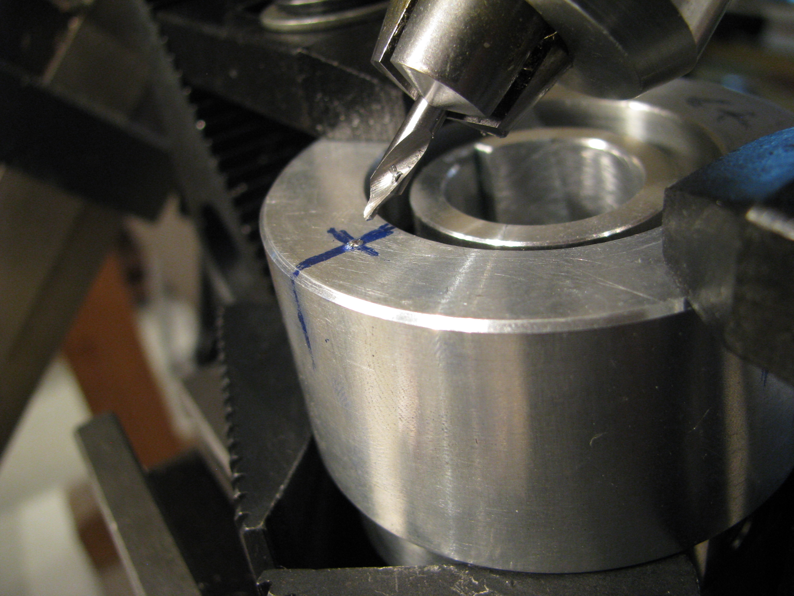
The outer race is supported underneath with some blocks so there is no side load on the bearing. A center drill is absolutely necessary for its stiffness. Drill just deep enough so that a normal bit will not jump out.
The first hole was a mess, the second better, and by the fourth it was perfect. I’m sure my second helicopter would be absolute perfection.

TR pre-assembled. Couldn’t resist spinning it around.
When I did this, however, I noticed that the slider bearing was not spinning cleanly. The bearing is defective and “ticks” as it spins. You can feel the “hitches” when you spin it by hand on the bench. I called Blake and he agreed that it didn’t sound right. It’s on its way back to Eagle to have a new one pressed in.